EP0064581B1 - Starter arrangement for internal combustion engine - Google Patents
Starter arrangement for internal combustion engine Download PDFInfo
- Publication number
- EP0064581B1 EP0064581B1 EP81302128A EP81302128A EP0064581B1 EP 0064581 B1 EP0064581 B1 EP 0064581B1 EP 81302128 A EP81302128 A EP 81302128A EP 81302128 A EP81302128 A EP 81302128A EP 0064581 B1 EP0064581 B1 EP 0064581B1
- Authority
- EP
- European Patent Office
- Prior art keywords
- switch
- relay
- contacts
- starter
- terminals
- Prior art date
- Legal status (The legal status is an assumption and is not a legal conclusion. Google has not performed a legal analysis and makes no representation as to the accuracy of the status listed.)
- Expired
Links
- 239000007858 starting material Substances 0.000 title claims abstract description 15
- 238000002485 combustion reaction Methods 0.000 title claims description 3
- 238000009413 insulation Methods 0.000 abstract 1
- 238000010276 construction Methods 0.000 description 2
- 238000004519 manufacturing process Methods 0.000 description 2
- 230000008878 coupling Effects 0.000 description 1
- 238000010168 coupling process Methods 0.000 description 1
- 238000005859 coupling reaction Methods 0.000 description 1
- 230000001419 dependent effect Effects 0.000 description 1
- 238000010586 diagram Methods 0.000 description 1
- 230000000694 effects Effects 0.000 description 1
- 238000012423 maintenance Methods 0.000 description 1
- 210000002105 tongue Anatomy 0.000 description 1
Images

Classifications
-
- F—MECHANICAL ENGINEERING; LIGHTING; HEATING; WEAPONS; BLASTING
- F02—COMBUSTION ENGINES; HOT-GAS OR COMBUSTION-PRODUCT ENGINE PLANTS
- F02N—STARTING OF COMBUSTION ENGINES; STARTING AIDS FOR SUCH ENGINES, NOT OTHERWISE PROVIDED FOR
- F02N11/00—Starting of engines by means of electric motors
- F02N11/10—Safety devices
- F02N11/101—Safety devices for preventing engine starter actuation or engagement
-
- F—MECHANICAL ENGINEERING; LIGHTING; HEATING; WEAPONS; BLASTING
- F02—COMBUSTION ENGINES; HOT-GAS OR COMBUSTION-PRODUCT ENGINE PLANTS
- F02N—STARTING OF COMBUSTION ENGINES; STARTING AIDS FOR SUCH ENGINES, NOT OTHERWISE PROVIDED FOR
- F02N11/00—Starting of engines by means of electric motors
- F02N11/08—Circuits specially adapted for starting of engines
- F02N11/087—Details of the switching means in starting circuits, e.g. relays or electronic switches
-
- F—MECHANICAL ENGINEERING; LIGHTING; HEATING; WEAPONS; BLASTING
- F02—COMBUSTION ENGINES; HOT-GAS OR COMBUSTION-PRODUCT ENGINE PLANTS
- F02N—STARTING OF COMBUSTION ENGINES; STARTING AIDS FOR SUCH ENGINES, NOT OTHERWISE PROVIDED FOR
- F02N15/00—Other power-operated starting apparatus; Component parts, details, or accessories, not provided for in, or of interest apart from groups F02N5/00 - F02N13/00
Definitions
- This invention relates to a starter arrangement for an internal combustion engine and of the type set forth in the introductory part of claim 1.
- the safety switch referred to is included in the energising circuit to preclude completion of this circuit when the engine is coupled to a load and may take various forms.
- the safety switch can be mechanically or hydraulically coupled to the gear selector mechanism, the clutch or hydraulic coupling in order to prevent starting of the engine when it is coupled to the wheels. This is important to prevent inadvertent movement of the vehicle when operating the starter and is especially important for a diesel engine which can be started without completing any ignition circuits, with the serious risk of a runaway vehicle.
- the object of this invention is to overcome the problem thus posed and the invention itself is defined in the characterising part of claim 1.
- the effect of the invention thus defined is to make manual completion of the circuit for the starter motor also dependent upon the closure of the safety switch.
- the invention may be placed upon the provision of the bridging contacts to dissuade the mechanic from other means of bridging the terminals but, for increased safety, the invention preferably employs the feature of claim 2.
- the positive terminal 11 of the battery 10 of a vehicle is connected to the external battery terminal 12 of a starter relay 13.
- the terminal 12 is connected to a corresponding contact 12A inside the relay.
- Another contact 14A inside the relay is connected via an external motor terminal 14 to the starter motor 15.
- the relay has an armature 16 and a solenoid coil 17.
- the armature connects the contact 12A with the contact 14A to energise the motor 15.
- the energising circuit for the coil 17 from the positive terminal 11 to an external coil terminal 21 comprises contacts 18 of an ignition switch, a safety switch 19 and a starter switch 20, all of which have to be closed to pull in the relay.
- Bridging contacts for connecting the terminals 12 and 21 are represented schematically as manually closable switches 22 making connection to cables 23 and 24 which lead to opposite sides of the safety switch 19. It can be seen that a manually operatable circuit for energising the solenoid coil 17 is thereby provided but which still requires the switch 19 to be closed.
- the circuit is from the battery terminal 11 through the terminal 12 on the relay, one switch 22, cable 24, switch 19, cable 23, the other switch 22 and terminal 21 to the solenoid coil.
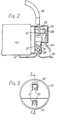
- Figs. 2 and 3 illustrate a preferred relay construction.
- the external terminals 12 and 21 are enclosed within an insulating housing 25 which prevents the terminals being bridged from outside.
- the main battery lead 26 and solenoid lead 27 are attached to the terminals 12 and 21 respectively.
- On the inside wall of the housing 25 there are fixed two bridging contacts 28 and 29 corresponding to the switches 22 of Fig. 1.
- the leads 23 and 24 are attached to the contacts 28 and 29 respectively which are opposed to the terminals 12 and 21 so that by pressing on the end of the housing 25, they can be pressed simultaneously into contact with the terminals 12 and 21.
- the contacts 28 and 29 can be on tongues 30 formed in the end wall by U-slots 31.
- the contacts 28 and 29 could be on an insulating carrier with a push button protruding through the housing 25.
- the contacts could be inside individual deformable, insulating caps of the terminals 12, 21.
- the leads may be desired to allow the manual starter facility only during manufacture. This is easily achieved by removing the leads 23, 24 on completion of manufacture, before delivery.
- the leads are preferably attached by connectors such that the leads can simply be pulled out of the housing 25, and also away from similar connectors at the two sides of the switch 19. Once this has been done it is not possible to start the motor otherwise than by way of all three switches 18, 19 and 20 because the housing 25 prevents access to the terminals 12 and 21 so that they cannot any longer be bridged.
Landscapes
- Engineering & Computer Science (AREA)
- Chemical & Material Sciences (AREA)
- Combustion & Propulsion (AREA)
- Mechanical Engineering (AREA)
- General Engineering & Computer Science (AREA)
- Connection Of Motors, Electrical Generators, Mechanical Devices, And The Like (AREA)
- Valve Device For Special Equipments (AREA)
- Ignition Installations For Internal Combustion Engines (AREA)
- Amplifiers (AREA)
- Glass Compositions (AREA)
- Secondary Cells (AREA)
- Cylinder Crankcases Of Internal Combustion Engines (AREA)
- Output Control And Ontrol Of Special Type Engine (AREA)
- Motor And Converter Starters (AREA)
- Control Of Throttle Valves Provided In The Intake System Or In The Exhaust System (AREA)
- Means For Warming Up And Starting Carburetors (AREA)
- Mechanisms For Operating Contacts (AREA)
- Relay Circuits (AREA)
Abstract
Description
- This invention relates to a starter arrangement for an internal combustion engine and of the type set forth in the introductory part of claim 1. The safety switch referred to is included in the energising circuit to preclude completion of this circuit when the engine is coupled to a load and may take various forms. For example, in the case of a vehicle engine, the safety switch can be mechanically or hydraulically coupled to the gear selector mechanism, the clutch or hydraulic coupling in order to prevent starting of the engine when it is coupled to the wheels. This is important to prevent inadvertent movement of the vehicle when operating the starter and is especially important for a diesel engine which can be started without completing any ignition circuits, with the serious risk of a runaway vehicle.
- It is nevertheless necessary to provide some means for starting the engine during construction, testing or even maintenance. For example it may be necessary to start the engine of a partially built vehicle which has not yet got its instrument panel. In many known devices, the battery and coil or motor terminals of the relay are accessible and close to each other so that it is a simple matter for the mechanic to bridge them and by-pass the relay. It is also well known to provide the relay with a manual button for closing the contacts. However these arrangements completely vitiate the function of the safety switch since the engine, especially a diesel engine can be started with the safety switch open.
- The object of this invention is to overcome the problem thus posed and the invention itself is defined in the characterising part of claim 1. The effect of the invention thus defined is to make manual completion of the circuit for the starter motor also dependent upon the closure of the safety switch.
- Reliance may be placed upon the provision of the bridging contacts to dissuade the mechanic from other means of bridging the terminals but, for increased safety, the invention preferably employs the feature of
claim 2. - The invention will be described in more detail, by way of example, with reference to the accompanying drawings, in which:
- Fig. 1 shows the circuit diagram of an embodiment of the invention;
- Fig. 2 is a schematic side view of one constructional form of part of the relay, partly in section on the line 2-2 of Fig. 3, and
- Fig. 3 is an end view of the relay.
- Referring to Fig. 1, the positive terminal 11 of the
battery 10 of a vehicle is connected to theexternal battery terminal 12 of astarter relay 13. Theterminal 12 is connected to acorresponding contact 12A inside the relay. Anothercontact 14A inside the relay is connected via anexternal motor terminal 14 to thestarter motor 15. - The relay has an armature 16 and a
solenoid coil 17. When the coil is energised, the armature connects thecontact 12A with thecontact 14A to energise themotor 15. The energising circuit for thecoil 17 from the positive terminal 11 to anexternal coil terminal 21 comprisescontacts 18 of an ignition switch, asafety switch 19 and astarter switch 20, all of which have to be closed to pull in the relay. - Bridging contacts for connecting the
terminals closable switches 22 making connection tocables safety switch 19. It can be seen that a manually operatable circuit for energising thesolenoid coil 17 is thereby provided but which still requires theswitch 19 to be closed. The circuit is from the battery terminal 11 through theterminal 12 on the relay, oneswitch 22,cable 24,switch 19,cable 23, theother switch 22 andterminal 21 to the solenoid coil. - Figs. 2 and 3 illustrate a preferred relay construction. The
external terminals insulating housing 25 which prevents the terminals being bridged from outside. Themain battery lead 26 andsolenoid lead 27 are attached to theterminals housing 25 there are fixed twobridging contacts switches 22 of Fig. 1. Theleads contacts terminals housing 25, they can be pressed simultaneously into contact with theterminals contacts tongues 30 formed in the end wall by U-slots 31. - Many constructional variants are possible. The
contacts housing 25. The contacts could be inside individual deformable, insulating caps of theterminals - It may be desired to allow the manual starter facility only during manufacture. This is easily achieved by removing the
leads housing 25, and also away from similar connectors at the two sides of theswitch 19. Once this has been done it is not possible to start the motor otherwise than by way of all threeswitches housing 25 prevents access to theterminals
Claims (3)
Priority Applications (11)
| Application Number | Priority Date | Filing Date | Title |
|---|---|---|---|
| AT81302128T ATE9026T1 (en) | 1981-05-13 | 1981-05-13 | STARTER ARRANGEMENT FOR COMBUSTION ENGINE. |
| DE8181302128T DE3165529D1 (en) | 1981-05-13 | 1981-05-13 | Starter arrangement for internal combustion engine |
| EP81302128A EP0064581B1 (en) | 1981-05-13 | 1981-05-13 | Starter arrangement for internal combustion engine |
| DE198181302128T DE64581T1 (en) | 1981-05-13 | 1981-05-13 | STARTING ARRANGEMENT FOR COMBUSTION ENGINE. |
| US06/365,852 US4436065A (en) | 1981-05-13 | 1982-04-05 | Starter arrangement for internal combustion engine |
| ES511926A ES8304269A1 (en) | 1981-05-13 | 1982-05-05 | Starter arrangement for internal combustion engine. |
| CA000402606A CA1184455A (en) | 1981-05-13 | 1982-05-10 | Starter arrangement for internal combustion engine |
| MX192635A MX151389A (en) | 1981-05-13 | 1982-05-11 | IMPROVEMENTS IN SYSTEM TO START AN INTERNAL COMBUSTION ENGINE |
| ZA823284A ZA823284B (en) | 1981-05-13 | 1982-05-12 | Starter arrangement for internal combustion engine |
| AU83633/82A AU548861B2 (en) | 1981-05-13 | 1982-05-12 | Starter circuit arrangement |
| JP57080831A JPS57195864A (en) | 1981-05-13 | 1982-05-13 | Starter apparatus of internal combustion engine |
Applications Claiming Priority (1)
| Application Number | Priority Date | Filing Date | Title |
|---|---|---|---|
| EP81302128A EP0064581B1 (en) | 1981-05-13 | 1981-05-13 | Starter arrangement for internal combustion engine |
Publications (2)
| Publication Number | Publication Date |
|---|---|
| EP0064581A1 EP0064581A1 (en) | 1982-11-17 |
| EP0064581B1 true EP0064581B1 (en) | 1984-08-15 |
Family
ID=8188299
Family Applications (1)
| Application Number | Title | Priority Date | Filing Date |
|---|---|---|---|
| EP81302128A Expired EP0064581B1 (en) | 1981-05-13 | 1981-05-13 | Starter arrangement for internal combustion engine |
Country Status (10)
| Country | Link |
|---|---|
| US (1) | US4436065A (en) |
| EP (1) | EP0064581B1 (en) |
| JP (1) | JPS57195864A (en) |
| AT (1) | ATE9026T1 (en) |
| AU (1) | AU548861B2 (en) |
| CA (1) | CA1184455A (en) |
| DE (2) | DE64581T1 (en) |
| ES (1) | ES8304269A1 (en) |
| MX (1) | MX151389A (en) |
| ZA (1) | ZA823284B (en) |
Families Citing this family (3)
| Publication number | Priority date | Publication date | Assignee | Title |
|---|---|---|---|---|
| JP2585338Y2 (en) * | 1991-11-25 | 1998-11-18 | 美和ロック 株式会社 | Automotive anti-theft device |
| FR2797536B1 (en) * | 1999-08-09 | 2001-11-02 | Valeo Equip Electr Moteur | DEVICE FOR CONTROLLING THE POWER SUPPLY OF A HEAT ENGINE STARTER, ESPECIALLY A MOTOR VEHICLE |
| ES2440725T3 (en) * | 2008-12-18 | 2014-01-30 | Abb Technology Ag | Switch arrangement for medium and high voltage switching devices |
Family Cites Families (10)
| Publication number | Priority date | Publication date | Assignee | Title |
|---|---|---|---|---|
| US2828382A (en) | 1956-02-13 | 1958-03-25 | Davidson Arnold | Ignition system safety switch |
| US2887588A (en) | 1956-07-09 | 1959-05-19 | William J Williams | Automatic remote control engine starting system |
| US2949105A (en) | 1958-03-17 | 1960-08-16 | Thermo Auto Matic Starter Inc | Automatic starting mechanism for automotive vehicles |
| US3071125A (en) | 1959-08-17 | 1963-01-01 | Rolls Royce | Engine starting systems |
| US2989644A (en) | 1960-01-25 | 1961-06-20 | Gen Motors Corp | Safety systems for electric fuel pumps |
| US3208021A (en) | 1962-09-12 | 1965-09-21 | Astra Corp | Shorting switch mechanism |
| US3553472A (en) * | 1967-11-13 | 1971-01-05 | John S Arlandson | Engine starting system |
| CA878762A (en) * | 1968-05-14 | 1971-08-17 | Monaco Paul | Remote starting system for automobiles |
| US3808914A (en) | 1971-04-22 | 1974-05-07 | Foote J Foundry Co | Engine and transmission with safety system |
| DE2802201A1 (en) * | 1978-01-19 | 1979-07-26 | Bosch Gmbh Robert | TURNING DEVICE FOR COMBUSTION MACHINERY |
-
1981
- 1981-05-13 DE DE198181302128T patent/DE64581T1/en active Pending
- 1981-05-13 EP EP81302128A patent/EP0064581B1/en not_active Expired
- 1981-05-13 AT AT81302128T patent/ATE9026T1/en not_active IP Right Cessation
- 1981-05-13 DE DE8181302128T patent/DE3165529D1/en not_active Expired
-
1982
- 1982-04-05 US US06/365,852 patent/US4436065A/en not_active Expired - Fee Related
- 1982-05-05 ES ES511926A patent/ES8304269A1/en not_active Expired
- 1982-05-10 CA CA000402606A patent/CA1184455A/en not_active Expired
- 1982-05-11 MX MX192635A patent/MX151389A/en unknown
- 1982-05-12 ZA ZA823284A patent/ZA823284B/en unknown
- 1982-05-12 AU AU83633/82A patent/AU548861B2/en not_active Ceased
- 1982-05-13 JP JP57080831A patent/JPS57195864A/en active Granted
Also Published As
| Publication number | Publication date |
|---|---|
| JPH0143152B2 (en) | 1989-09-19 |
| MX151389A (en) | 1984-11-13 |
| ES511926A0 (en) | 1983-02-16 |
| ATE9026T1 (en) | 1984-09-15 |
| AU8363382A (en) | 1982-11-18 |
| JPS57195864A (en) | 1982-12-01 |
| ZA823284B (en) | 1983-12-28 |
| AU548861B2 (en) | 1986-01-02 |
| DE3165529D1 (en) | 1984-09-20 |
| EP0064581A1 (en) | 1982-11-17 |
| CA1184455A (en) | 1985-03-26 |
| ES8304269A1 (en) | 1983-02-16 |
| US4436065A (en) | 1984-03-13 |
| DE64581T1 (en) | 1983-05-11 |
Similar Documents
| Publication | Publication Date | Title |
|---|---|---|
| JPH07335330A (en) | Electric connector with switch | |
| US5694100A (en) | Motor vehicle starter having an auxiliary control relay, and a contactor for such a starter | |
| US4286172A (en) | Safety jumper cables | |
| US4527111A (en) | Safety jumper cables | |
| EP0064581A1 (en) | Starter arrangement for internal combustion engine | |
| US6734380B2 (en) | Add-on unit for contactor-circuit breaker | |
| JPS57118930A (en) | Engine starting circuit for vehicle with automatic transmission unit | |
| DE19810954A1 (en) | Starting device for IC engine in vehicle with high safety requirements e.g. for tanker vehicle | |
| US4064547A (en) | Vehicle antitheft device | |
| GB2114827A (en) | A switching arrangement for starting an internal-combustion engine by means of several electric starting motors | |
| KR920704005A (en) | Remote control device for starting and stopping diesel and gasoline engines | |
| GB2199704A (en) | Mining vehicle battery switching installation | |
| US5240438A (en) | Electrical or electronical motor control | |
| JPH0723578Y2 (en) | Starter starting circuit | |
| JPS629149Y2 (en) | ||
| JPS6419171A (en) | Automatic starting device for engine at set time | |
| KR100337820B1 (en) | Starting / Heating Circuit of Electric Vehicle | |
| JPH05231704A (en) | Controller for air conditioner | |
| JPS6210442Y2 (en) | ||
| SU1193032A1 (en) | Vehicle engine starting device | |
| ITMI952158A1 (en) | ELECTROMEGNETIC SWITCH, ESPECIALLY ENGAGEMENT RELAY FOR STARTING DEVICES OF ENDOTHERMIC ENGINES | |
| KR970075333A (en) | When the parking brake of the vehicle is released, the engine can not be started. | |
| US2119672A (en) | Means for controlling the starting of internal combustion engines | |
| KR890003747B1 (en) | Safe starting apparatus for automobile | |
| JPS56160666A (en) | Diagnostic device for electronic control apparatus for vehicle |
Legal Events
| Date | Code | Title | Description |
|---|---|---|---|
| PUAI | Public reference made under article 153(3) epc to a published international application that has entered the european phase |
Free format text: ORIGINAL CODE: 0009012 |
|
| 17P | Request for examination filed |
Effective date: 19820405 |
|
| AK | Designated contracting states |
Designated state(s): AT DE FR GB IT SE |
|
| ITCL | It: translation for ep claims filed |
Representative=s name: LENZI & C. |
|
| EL | Fr: translation of claims filed | ||
| TCAT | At: translation of patent claims filed | ||
| TCNL | Nl: translation of patent claims filed | ||
| DET | De: translation of patent claims | ||
| ITF | It: translation for a ep patent filed | ||
| RBV | Designated contracting states (corrected) |
Designated state(s): AT DE FR GB IT SE |
|
| GRAA | (expected) grant |
Free format text: ORIGINAL CODE: 0009210 |
|
| AK | Designated contracting states |
Designated state(s): AT DE FR GB IT SE |
|
| REF | Corresponds to: |
Ref document number: 9026 Country of ref document: AT Date of ref document: 19840915 Kind code of ref document: T |
|
| REF | Corresponds to: |
Ref document number: 3165529 Country of ref document: DE Date of ref document: 19840920 |
|
| ET | Fr: translation filed | ||
| PLBE | No opposition filed within time limit |
Free format text: ORIGINAL CODE: 0009261 |
|
| STAA | Information on the status of an ep patent application or granted ep patent |
Free format text: STATUS: NO OPPOSITION FILED WITHIN TIME LIMIT |
|
| 26N | No opposition filed | ||
| PG25 | Lapsed in a contracting state [announced via postgrant information from national office to epo] |
Ref country code: SE Effective date: 19880514 |
|
| ITTA | It: last paid annual fee | ||
| PGFP | Annual fee paid to national office [announced via postgrant information from national office to epo] |
Ref country code: GB Payment date: 19930419 Year of fee payment: 13 |
|
| PGFP | Annual fee paid to national office [announced via postgrant information from national office to epo] |
Ref country code: FR Payment date: 19930513 Year of fee payment: 13 Ref country code: AT Payment date: 19930513 Year of fee payment: 13 |
|
| PGFP | Annual fee paid to national office [announced via postgrant information from national office to epo] |
Ref country code: DE Payment date: 19930703 Year of fee payment: 13 |
|
| PG25 | Lapsed in a contracting state [announced via postgrant information from national office to epo] |
Ref country code: GB Effective date: 19940513 Ref country code: AT Effective date: 19940513 |
|
| GBPC | Gb: european patent ceased through non-payment of renewal fee |
Effective date: 19940513 |
|
| EUG | Se: european patent has lapsed |
Ref document number: 81302128.4 Effective date: 19890510 |
|
| PG25 | Lapsed in a contracting state [announced via postgrant information from national office to epo] |
Ref country code: FR Effective date: 19950131 |
|
| PG25 | Lapsed in a contracting state [announced via postgrant information from national office to epo] |
Ref country code: DE Effective date: 19950201 |
|
| REG | Reference to a national code |
Ref country code: FR Ref legal event code: ST |