EP0064080B1 - Safety mechanism for hoisting drums - Google Patents
Safety mechanism for hoisting drums Download PDFInfo
- Publication number
- EP0064080B1 EP0064080B1 EP19810903165 EP81903165A EP0064080B1 EP 0064080 B1 EP0064080 B1 EP 0064080B1 EP 19810903165 EP19810903165 EP 19810903165 EP 81903165 A EP81903165 A EP 81903165A EP 0064080 B1 EP0064080 B1 EP 0064080B1
- Authority
- EP
- European Patent Office
- Prior art keywords
- brake
- safety
- shaft
- safety brake
- drum
- Prior art date
- Legal status (The legal status is an assumption and is not a legal conclusion. Google has not performed a legal analysis and makes no representation as to the accuracy of the status listed.)
- Expired
Links
Images


Classifications
-
- B—PERFORMING OPERATIONS; TRANSPORTING
- B66—HOISTING; LIFTING; HAULING
- B66D—CAPSTANS; WINCHES; TACKLES, e.g. PULLEY BLOCKS; HOISTS
- B66D1/00—Rope, cable, or chain winding mechanisms; Capstans
- B66D1/54—Safety gear
- B66D1/58—Safety gear responsive to excess of load
-
- B—PERFORMING OPERATIONS; TRANSPORTING
- B66—HOISTING; LIFTING; HAULING
- B66D—CAPSTANS; WINCHES; TACKLES, e.g. PULLEY BLOCKS; HOISTS
- B66D5/00—Braking or detent devices characterised by application to lifting or hoisting gear, e.g. for controlling the lowering of loads
- B66D5/02—Crane, lift hoist, or winch brakes operating on drums, barrels, or ropes
- B66D5/24—Operating devices
Definitions
- the invention relates to a safety system according to the preamble part of claim 1.
- a safety-system as known from US-A-4 177 973 comprises a mechanical out-of-sync detector having two coaxially arranged discs, each being driven by one component of the hoist device. Both discs are provided with a peripheral recess and rotate with the drum and drive motor respectively and with the same speed. During normal operation of the hoist system both recesses are not aligned with each other. A cam follower of a rotatably mounted switch lever rides on the peripheries of both discs simultaneously. The lever cooperates with an electrical triggering switch forthe actuation of the safety brake. In case of a failure in the main drive train between the drive motor and the drum the discs rotate with different speeds until both recesses are aligned.
- the cam follower then falls into the aligned recesses and actuates the trigger switch for the safety brake.
- the out-of-sync detector works mechanically but can actuate the safety brake only with the help of electrical power supply.
- One disadvantage of said embodiment of the safety system is its strict dependency on a correct electrical power supply which can easily be interrupted under rough working conditions.
- a further disadvantage is that in such hoist systems in practice the gear ratios in both drive trains from the motor to the output of the detector cannot be matched precisely enough so that there will be a constant out-of-sync rotation which accumulates and leads to an inadvertent safety-brake-setting ( nuisance-brake-setting).
- hoist systems conventionally contain a torque-limiting device or a slip clutch within the drive trains, an inherent disadvantage of which is a certain unavoidable slippage.
- the mechanical out-of-sync detector cannot differentiate between uncritical differences in speed and direction of the two supervised drive train branches and serious critical differences dueto initial drive train failures but, triggers the actuator of the safety brake in both cases.
- US-A-4177 973 discloses a further embodiment of an electropneumatically working safety system for a hoist assembly, said safety system comprising an electrical out-of-sync detector with counters and comparators and an electrically working error correcting means.
- the counters and comparators count and compare the number of pulses derived from the motor and the drum shaft rotation respectively via encoders. As soon as a predetermined difference between the pulses counted is exceeded a solenoid valve in the supply line for a release mechanism of the actuator of the safety brake is actuated in order to set the safety brake.
- Said electrical error correcting means is in the form of a sensitvity adjustment and is associated with the comparators in order to compensate speed differences between both supervised drive train branches or to take up constant mechanical gear lash in the drive train.
- Said electrical error correcting means influences the safety system independently from the working speed of the hoist device.
- Said embodiment of the safety system is strictly dependent on external power sources. i.e., pneumatical and electrical power, the constant supply of which cannot be ensured under rough working conditions. In practice the safety system cannot completely avoid nuisance-brake-settings. Furthermore, the electrical and pneumatical components of the safety system strongly suffer from vibrations, dirt and bad weather conditions.
- the safety-system according to the invention is together with its error correcting means completely mechanical and thus operates reliably even under rough working conditions. Its safety function does not depend on external power sources because the mechanical drive power for the error correcting means can be directly derived from the drive trains or from an internal mechanical power source.
- the undesirable influence of creep or unprecisely matched gear ratios is compensated with the help of an intentionally produced correcting motion which nullifies the brake setting output resulting, e.g. from creep.
- the sensitivity of the safety system and particularly the error correcting means adapts itself to the working speed of the hoist system in order to ensure an actuation of the safety brake in critical and dangerous situations and independently from the working speed.
- a hoist system includes an operating brake 2 coupled to a motor shaft 2a which is powered by a motor 3.
- a coupling 4 couples the motor to a conventional gear reduction unit 5, such as a 500:1 reduction, which has an output shaft 7 rotatably carried in a pillow block 8.
- a drum pinion 9 meshes with the drum gear 10.
- a drum 11 is rotated by the drum gear on a shaft 11a a which is rotatably supported in a pair of spaced pillow blocks 13.
- the hoist system is provided with a second brake, such as a band brake 14, wrapped on a brake drum 12.
- a brake-applying assembly or brake actuator 15 will set the brake in response to a detected failure or other hazard condition.
- a torque limiter assembly 6 is provided to limit the torque which would be imposed from high-speed rotational kinetic energy of the motor and high-speed drive elements of the gear reduction and motor drive if a load hang-up, overload or two-blocking occurs.
- a mechanical differential, out-of-sync detector 20 is provided for detecting the failure or hazard condition.
- the detector also provides the mechanical force for applying the band brake 14.
- the detector merely signals the out-of-sync detection and a separate brake actuator sets the brake, as in Figs. 7 and 8.
- the out-of-sync detector 20 includes a first input shaft 30 which is coupled to the motor shaft 2a by a right angle drive 19 having a gear reduction equivalent to that of the total gear reduction between the motor and the drum.
- a right angle drive 18 also couples the drum shaft 11 a to a second input shaft 31 to the detector 20.
- the purpose of the gear reduction in right angle drive 19 is to bring the two input shafts entering the dectector to approximately the same speed. Other forms of speed reduction can also be provided.
- Each of the input shafts 30, 31 (Fig. 3), is keyed to a drive gear which meshes with a side gear 26.
- the side gears 26 are keyed to pinion gears 27 that mesh with a planetary gear 27a of a planet carrier 28.
- Equal and opposite rotational velocities of the input shafts 30 and 31 will cause the pinion gears 27 to rotate the gear 27a about a planet carrier post 28a that is fixed by a pin 46 to an output shaft 29 carried in bearings 25.
- an angular velocity will be created in the output shaft 29, the speed of which will depend on the relative variation between the velocities of the two input shafts.
- the rotational output of the output shaft 29 will immediately reach a maximum speed. It is this rotation of the output shaft which triggers the brake actuation and, in one embodiment, creates or generates the force necessary for applying the brake on the brake drum 12. It is possible to place this brake on a downstream pinion shaft in close proximity to the drum rather than directly on the drum. The purpose of this brake is to apply a stopping force on the drum as close to the drum as is practicable so that no substantial risk occurs from a failure of some drive element between the brake and the drum.
- the input shaft 31 to the detector could also be from any location in the drive train between the motor and drum, which location is at the desired point to be monitored. Preferably, this location, however, will be at or close to the drum.
- a brake actuator mechanism 15 in Fig. 1 includes a lever 16a keyed to an extension 29a of shaft 29.
- the lever is coupled to the free end of the brake band 14 such that rotation of the lever 16a in either direction will set the band brake.
- the lever 16a is provided with a notch 16b in which is inserted a spring-centered cog 17.
- a clutch 32 couples shaft 29 to its extension 29a.
- a clutch throw out bar 33 follows a cam 34 on the drum to decouple the shaft extension 29a once each rotation of the drum.
- lever 16a will rotate toward the maximum angle, but the clutch 32 will decouple the lever 16 Q before it rotates far enough for the cog to leave the notch 16b.
- the shaft 29 will rotate at a high velocity and the drum will be stopped before one or perhaps at the most two more revolutions of the drum are possible.
- the torque-limiting device 6 generally has a driven gear 40 which is driven by one of the upper stages of the gear reduction in the gear case 5.
- the gear 40 is provided with clutch facing 39 which is splined, as at 41, to a shaft 42.
- a spring 37 pushes a pressure plate 38 against the clutch facing, thus releasably holding the gear 40 in driving engagement with the shaft 42.
- a pinion gear 44 is fixed to the shaft 42 by a key 45.
- a centrifugal clutch 47 (Fig. 5) is provided to decouple input shaft 30 from motor shaft 2a when the motor shaft rotates at an overspeed above some pretermined percentage of its normal driven speed. That is, if some failure occurs which causes the motor to rotate beyond its set speed, the shaft 30 will become decoupled and stop, thus providing a variation between the relative velocities of shaft 30 and shaft 31 to provide a rotational output to output shaft 29 and set the brake. It is important in the differential assembly that the differential rotation can not drive the input shafts backwards, and thus there are provided drag mechanisms on each of the input shafts to assure that only the output shaft is rotated when one of the input shafts changes its velocity relative to the other.
- Continuous friction drags could be provided on each of the shafts for this purpose, or the inputs could be through worm gear drives; but in the preferred embodiment, the shafts are broken into two sections, namely, an external section 31e and an internal section 31i and an external section 30e and an internal section 30i.
- the internal and external sections of each shaft are joined by a conventional one-way clutch or "NO BAK" clutching device 21. These devices are positioned so that the external section 30e, when driving in either direction, will freely rotate the internal section 30i.
- the clutch on the drum input shaft is positioned so that when external section 31 e is providing a driving input, the internal section 31i i will freely rotate. The converse is not true, however.
- An overspeed clutch 47 is provided in a preferred embodiment. It is advantageous to employ a mechanical overspeed clutch having a clutch friction plate 48 keyed to shaft 2a and an opposed friction and pressure plate 49 keyed to a separate stub shaft 50 which drives the right angle gear box 19.
- a spring 52 is compressed by centrifugal governor weights 54 to hold the friction plates in driving engagement.
- the weights 54 swing outwardly and spring 52 is released, thereby allowing plates 48 and 49 to slip relative to one another.
- the detector signals the out-of-sync condition and the brake 14 is set.
- Control systems for high-performance hoists are sometimes designed to sense the lifted load and to command motor 3 to operate at higher than full-load rated speed when handling a lighter load. This may be as high as 300 percent when operating under such no-load condition.
- Conventional overspeed drives are generally set in this no-load case to cut out at more than 300 percent full-load speed. This reduces the safety when handling a full load.
- the clutch 47 can also be made load-sensitive.
- a bell crank 56 is threaded in a nut 58 such that when screwed away from spring 52, the weights 54 will have less pressure on them and will open to release the discs 48 and 49 sooner or at a lower overspeed. If the bell crank is screwed in the opposite direction, higher overspeed can occur before the clutch plates are separated.
- Motion of the bell crank 56 is provided by a line 60 coupled to a pivoted arm 62 that is balanced by a calibrated spring 64.
- the drum line 70 is reaved about a travelling block 72 and thence to a sheave 73 on arm 62. As the load is increased, arm 62 is lowered, thus moving bell crank 56.
- the detector 20 can signal an electrical shutoff or brake-setting device, it advantageously preferably signals or triggers a mechanical brake actuator.
- the detector can itself apply the brake.
- Two forms of triggering devices for setting the brake 14 are illustrated in Figs. 7 and 8. It is common to both these triggering devices that a large spring force can be applied to set the brake, but a small trigger release force is all that is necessary to release the spring.
- the brake band 14 is set by a spring 74 having a large spring force, as is necessary for high-load capacity drums.
- a lever 75 is engaged by a trigger 76 which holds the spring in a cocked position.
- the trigger 76 is locked by a conventional trigger release cam 78.
- a solenoid 80 having an extendible arm 81 pivotally mounts one end of the cam 78.
- the cam is also pivoted at 83 and has an end 84 that abuts the trigger 76.
- a spring 89 urges the cam 78 into the phantom-line position to disengage from the trigger 76.
- solenoid 80 When solenoid 80 is energized, the trigger release cam . is in the solid-line position.
- a relatively slow-speed rotary screw drive 90 moves the trigger, solenoid, and trigger release to the left.
- the trigger strikes a cam 92 that rotates the trigger counterclockwise, and the solenoid is energized to again hold the trigger in the cocked position. Movement of the screw to shift the trigger to the right then reengages the lever 75 and recompresses the spring 74. Since the spring can be compressed slowly, the highly leveraged screw drive is easily able to overcome very large spring forces.
- Fig. 8 illustrates a mechanical trigger release.
- the cam can be electrically de-energized without having to set the brake 14, which is a disadvantage in the embodiment of Fig. 7.
- the lever 16a (Fig. 1), rather than being coupled directly to the brake band 14, is coupled to an elongated cable 94that is connected to the trigger release cam 78 by a lost- motion slot 95.
- the cable 94 is pulled, pivoting trigger release cam 78 into the phantom-line position to release trigger 76 in the same manner as in Fig. 7.
- Resetting of the spring 74, trigger 76, and cam 78 is similar to the above description of Fig. 7.
- Fig. 3A illustrates a modification of the detector 20 capable of providing a signal for setting a brake actuator.
- the detector output shaft 29 is provided with a flyball governor 97 that meshes with a rack 98 slidably mounted in the shaft 29.
- a flyball governor 97 that meshes with a rack 98 slidably mounted in the shaft 29.
- teeth on the levers meshing with the rack extend the rack.
- the rack engages a normally closed switch 99 to open the switch and de-energize solenoid 80, for example, to set the brake.
- a normally energized electric clutch 100 can be added to any of the embodiments to decouple the motor shaft from the detector for setting the brake automatically if an electrical power failure occurs.
- this clutch or the overspeed clutch could also be placed on the drum side of the input to the differential detector.
- the motor input shaft will then cause the output shaft 29 to rotate rapidly; for example, at about 600 ⁇ /min, since no slippage or back rotation can occur due to the clutch or drag 21 on the drum input shaft.
- Rotation of the output shaft 29 will immediately rotate the ball governor 97 or rotate the lever 16a, and the force applied by this rotation will be used either as a signaling device, as in Figs. 7 and 8, to setthe brake, or, in a totally mechanical system, as in Fig. 1, to directly tighten the band brake.
- the clutch 47 will disengage the motor shaft from the detector, stopping the input shaft 30 and providing an out-of-sync rotation of shaft 29.
- the shaft 29 again will be rotated to set the brake.
- a motor M is drivingly coupled to a drum D by a conventional power transmission main drive train including a gear reduction unit 210 and a passive energy absorption device 212.
- the opposite end of the motor M is connected through a secondary drive train to an input shaft 214 of an out-of-sync detector 216 (Fig. 11).
- the motor M is joined to the input shaft 214 by an electric clutch 218 and right-angle drive element 219.
- the motor M is provided with an electrically controlled operational brake 220, which is set when electrically de-energized, i.e., in the absence of electricity.
- the electrical clutch 218 is employed between the motor M and the motor input shaft 214foroverspeed protection. For this purpose, the clutch 218 is drivingly coupled between the input shaft 214 and the motor when the electric motor is being energized, but becomes decoupled when the electricity is removed from the motor or during a total electrical blackout.
- the clutch also will become decoupled when the drum's rotational velocity exceeds a predetermined value, as in a hazard condition of the type in which the motor controller directs the motor to run at an unsafe overspeed condition.
- "Overspeed,” as used herein, is a well known term in the art to signify a condition when, forthe particular hoisting system, the motor is running at an excessive speed, for example, 150 and 200 percent of its normal operating speed.
- a second input shaft 222 to the detector 216 is coupled with the drum D.
- the drum is provided with a safety brake 224.
- the brake is set by a brake actuator 226 which recieves a signal from the detector 216 of a failure or hazard condition, which signal is transmitted via a mechanical cable 227.
- the detector 216 is provided with a gear reduction 228 which couples the drum shaft 222 to a differential gear assembly 230 via a NO-BAK coupling 229 which will drivingly couple or transmit motion from the input shaft 222 into the differential 230 in either rotational direction, but will lock up and not transmit motion in the reverse direction, that is, from the differential assembly 230 back to the input shaft 222.
- the differential assembly 230 contains a set of bevel gears 236-239 which are freely rotatable on spindles that are keyed to a housing 240.
- the housing is keyed to a spindle 242, whereas gears 236 and 238 are freely rotatable on spindle 242.
- Clockwise rotation in the direction of arrow 243 of the gear 236, with the housing held stationary, will result in counterclockwise rotation of gear 238 in the direction of arrow 244. If the entire housing rotates in a clockwise direction, as shown by arrow 245, then gear 238 will rotate, in a clockwise direction.
- the rotational directions for purposes of this description will be viewed arbitrarily as looking in the direction of arrows 14-14 of Fig. 11, and also are arbitrarily shown as in the load lowering mode).
- Gear 238 is keyed to an output shaft 249 on which is mounted to a one-way sprag clutch 250.
- the shaft 249 will freewheel in the counterclockwise direction of rotation in the sprag clutch 250, but in the opposite direction will lock up with the clutch, causing rotation of the clutch.
- the input to the differential housing 240 is through the NO-BAK clutch 229.
- the second input to the differential assembly is through worm gear 251, driven by a screw shaft 252.
- Worm gear 251 is keyed to gear 236.
- Shaft 214 from motor M is connected to shaft 252 through a slip correction device 254 (Fig. 15).
- the slip correction device 254 includes a first set of gears 256 and 257 having diametrical ratios which produce a slower rotational velocity in shaft 252 than is in shaft 214.
- Gear 257 is coupled to shaft 252 through a friction slip clutch 258.
- a second set of gears 260 and 261 result in a rotational velocity of shaft 252 which is greater than the rotational velocity of shaft 214.
- Gear 260 is coupled to shaft 214 through a one-way sprag clutch 263.
- the result of this gearing and clutching arrangement is that when shaft 214 is turning counterclockwise (looking left in Fig. 15), for example, the drive will be through gears 256 and 257 to reduce the velocity of shaft 252. Gear 260 will freewheel on shaft 214.
- sprag clutch 263 locks gear 260, resulting in shaft 252 being rotated at a higher velocity than shaft 214, with gear 257 slipping in clutch 258.
- this slip correction device is to provide an input direction and velocity to the differential 230 which are different than those from the input from the NO-BAK 229 from the drum (assuming that the gear reductions between the drum and its differential input and the motor and the differential input through gear 251 are at or about the same reductions) such that gear 238 will always result in a net unidirectional rotation output in the counterclockwise direction.
- the counterclockwise component added to the gear 238 allows the output shaft 249 to rotate in a freewheeling condition; and should limited slip occur between the motor and the drum due to a passive energy absorption device, such as device 212, then the slip will be less than that required to trig the brake and the added component of velocity added to the gear 238 and will null out the slip during operation of the hoist.
- a passive energy absorption device such as device 212
- the slip will be less than that required to trig the brake and the added component of velocity added to the gear 238 and will null out the slip during operation of the hoist.
- the motor is rotated in a direction to rotate the drum in a raising mode.
- shaft 252 will be made to turn slower than shaft 214.
- the signal or clockwise movement of sprag clutch 250 is provided to trigger release of the brake in a manner which allows the trigger to be reset without manual intervention. This is an advantage when testing an installed system as well as to reset the brake during inadvertent trips or when the brake has been set intentionally by a failure or by the operator of the hoist.
- This brake-actuating mechanism is best shown in Figs. 9, 10 and 11.
- the band brake 224 is connected at its free end to a bell crank 270.
- This bell crank is connected to a trigger mechanism 272 of a type similar to that shown in Figs. 7 and 8.
- the trigger mechanism 272 employs a catch 274 having a cam surface 276 and a lower cam surface 278.
- a latch 280 has an abutment end 282.
- the brake is set by a large force-applying compression spring, shown schematically as 284.
- the brake is retracted or reset by a conventional air bag or cylinder and piston 286.
- the air bag is such that it is energized to compress the spring 284 and loosen the brake band.
- the end 282 of the latch 280 engages the cam surface 276.
- the latch is raised by engagement of a boss 288 on the backside of the catch.
- the arrangement of the cams 276 and 278 are such that they will try to rotate latch 280 clockwise in a brake-releasing conditon, but so long as the latch 280 is held in the upright condition, the catch 274 cannot move.
- latch 280 once latch 280 is held in the raised position, catch 274 cannot move and the air can be vented from the air bags 286.
- the force by the spring 284 will cause approximately 0,068 tons of force to be required to hold the latch 280 in the raised position.
- This force is to be contrasted with the cocking force of several thousand pounds (2,72 tons, for example) that will be placed in the spring 284 by the air bags as is commonly necessary for setting this type of band brake.
- the advantage of course, as with the embodiment of Figs. 1-8, is that a very quick acting, small restraining force can be used to trigger or release a much larger brake-applying force.
- latch 280 is coupled by the cable 227 to a slide 292.
- the slide is held in a raised position by a smaller force compression spring 294 of perhaps 10 to 15 Kp force.
- the slide 292 is carried in a track 295.
- the slide is held up by a roller 296 which is carried on a wedge ring 298.
- the wedge ring is rotated counterclockwise by a reset cable 300, which is coupled to a tension spring 302. Due to the downward pull by cable 227, wedges 306 on the wedge ring lock into a wedge carrier 307 that is fixed to the sprag clutch 250 in the position shown in solid lines in Fig. 14 (the operational position). In this condition, of course, the output shaft 249 from the differential will either be stationary or rotating in the counterclockwise direction so that the wedge ring freely rotates on the shaft 249.
- Figs. 16 and 17 illustrate a simplified embodiment usable with slip correction device 254.
- the differential detector of Fig. 16 employs a motor input shaft 252, from the motor and a hollow input shaft 242 from the drum.
- a collar 320 is pivotally connected to a bell crank 321.
- a spring 322 holds the bell crank in a counterclockwise direction and is equivalent to the spring 294 of Fig. 14.
- Cable 227 is attached to the right-hand end of the bell crank.
- the collar 320 is keyed within an axial slot 324 in the shaft 252.
- a roller 326 is rotatably mounted on the collar. The roller is held against a cam surface 330 which forms part of a cam block 332.
- the cam block is joined to shaft 242 by a friction clutch 333 and a one way clutch 338, positioned by needle thrust bearings 334 and radial bearings 337.
- the cam block freewheels on the shaft 242 in one direction of rotation, but is joined to the shaft 242 in locked arrangement by the one-way sprag clutch 338 and friction clutch 333.
- the cam block moves with the shaft 242 and is held in the direction of the arrow 340 by a coil spring 342.
- the cable 227 produces approximately a 0,068 tons pull on the collar, urging it axially to the right in Fig. 16, energizing the friction clutch 333.
- the device senses a differential movement between the shaft 242 and the shaft 252 in a predetermined direction to cause the sprag clutch 338 to rotate clockwise in the embodiment illustrated to rotate the cam block and release the collar 320.
- the normal operating rotations will produce either a zero differential rotation between shafts 252 and 242, if there are perfectly matched gear reductions between the motor and drum and the detector and if there is no relative slippage in the drive trains. If these conditions do not exist, then a unidirectional rotational differential exists. In either case, a failure or hazard condition will cause an output rotation in a predetermined direction and opposite said unidirectional rotation, if such is in effect, to set the safety brake.
- NO-BAK 360 will allow shaft 252 to be driven from the motor but will not allow shaft 252 to backdrive through NO-BAK 360. Now assume that the motor shaft fails, creating a failure condition. NO-BAK 360 locks shaft 252, shaft 242 thus turns clockwise faster than shaft 252, clutch 338 engages, and the cam block 332 gets rotated clockwise, causing roller 326 to enter slot 344 and set the brake.
- a further advantage is that whenever the operational brake is set, any slippage or failure in the operational brake will also be detected and set the safety brake. This overcomes a major problem in hoists because the brakes can otherwise wear severely without detection by the operator and allow the load to slip.
Abstract
Description
- The invention relates to a safety system according to the preamble part of claim 1.
- A safety-system as known from US-A-4 177 973 comprises a mechanical out-of-sync detector having two coaxially arranged discs, each being driven by one component of the hoist device. Both discs are provided with a peripheral recess and rotate with the drum and drive motor respectively and with the same speed. During normal operation of the hoist system both recesses are not aligned with each other. A cam follower of a rotatably mounted switch lever rides on the peripheries of both discs simultaneously. The lever cooperates with an electrical triggering switch forthe actuation of the safety brake. In case of a failure in the main drive train between the drive motor and the drum the discs rotate with different speeds until both recesses are aligned. The cam follower then falls into the aligned recesses and actuates the trigger switch for the safety brake. The out-of-sync detector works mechanically but can actuate the safety brake only with the help of electrical power supply. One disadvantage of said embodiment of the safety system is its strict dependency on a correct electrical power supply which can easily be interrupted under rough working conditions. A further disadvantage is that in such hoist systems in practice the gear ratios in both drive trains from the motor to the output of the detector cannot be matched precisely enough so that there will be a constant out-of-sync rotation which accumulates and leads to an inadvertent safety-brake-setting (nuisance-brake-setting). Furthermore, such hoist systems conventionally contain a torque-limiting device or a slip clutch within the drive trains, an inherent disadvantage of which is a certain unavoidable slippage. The mechanical out-of-sync detector cannot differentiate between uncritical differences in speed and direction of the two supervised drive train branches and serious critical differences dueto initial drive train failures but, triggers the actuator of the safety brake in both cases.
- However, US-A-4177 973 discloses a further embodiment of an electropneumatically working safety system for a hoist assembly, said safety system comprising an electrical out-of-sync detector with counters and comparators and an electrically working error correcting means. The counters and comparators count and compare the number of pulses derived from the motor and the drum shaft rotation respectively via encoders. As soon as a predetermined difference between the pulses counted is exceeded a solenoid valve in the supply line for a release mechanism of the actuator of the safety brake is actuated in order to set the safety brake. Said electrical error correcting means is in the form of a sensitvity adjustment and is associated with the comparators in order to compensate speed differences between both supervised drive train branches or to take up constant mechanical gear lash in the drive train. Said electrical error correcting means influences the safety system independently from the working speed of the hoist device. Said embodiment of the safety system is strictly dependent on external power sources. i.e., pneumatical and electrical power, the constant supply of which cannot be ensured under rough working conditions. In practice the safety system cannot completely avoid nuisance-brake-settings. Furthermore, the electrical and pneumatical components of the safety system strongly suffer from vibrations, dirt and bad weather conditions.
- It is a task of the present invention to achieve a reliable safety-system of the mechanical type which can withstand rough operating conditions, which avoids nuisance-brake-settings of the safety brake, and which is independent from electrical power supply.
- This task can be achieved with the feature combination in the characterizing part of claim 1.
- The safety-system according to the invention is together with its error correcting means completely mechanical and thus operates reliably even under rough working conditions. Its safety function does not depend on external power sources because the mechanical drive power for the error correcting means can be directly derived from the drive trains or from an internal mechanical power source. The undesirable influence of creep or unprecisely matched gear ratios is compensated with the help of an intentionally produced correcting motion which nullifies the brake setting output resulting, e.g. from creep. The sensitivity of the safety system and particularly the error correcting means adapts itself to the working speed of the hoist system in order to ensure an actuation of the safety brake in critical and dangerous situations and independently from the working speed.
- Preferred embodiments are contained in the depending claims.
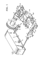
The drawings: - Fig. 1 is a schematic plan view of a hoisting mechanism employing the safety system of this invention.
- Fig. 2 is a section along the line 2-2 of Fig. 1.
- Fig. 3 is a fragmentary section taken along line 3-3 of Fig. 1.
- Fig. 3A is a schematic fragmentary section of another embodiment of detection device employed in one form of safety system.
- Fig. 4 is a side elevation of the hoisting device and safety system of Fig. 1.
- Fig. 5 is a fragmentary section of an overspeed clutch.
- Fig. 6 is a load-sensitive control for the overspeed clutch of Fig. 5.
- Fig. 7 is a schematic elevation of another embodiment of brake-setting apparatus.
- Fig. 8 illustrates a mechanical brake-setting apparatus.
- Fig. 9 is a schematic plan of a safety system.
- Fig. 10 is a fragmentary enlarged section of a portion of a brake-setting trigger employed in the apparatus of Fig. 9.
- Fig. 11 is a schematic taken generally along the line 11-11 of Fig. 12, illustrating a differential assembly embodiment of the system shown in Fig. 9.
- Fig. 12 is a side elevation of a portion of the apparatus shown in Fig. 9.
- Fig. 13 is an isometric of a portion of the system.
- Fig. 14 is a section taken generally along the line 14-14 of Fig. 11.
- Fig. 15 is a section taken generally along the line 15-15 of Fig. 12.
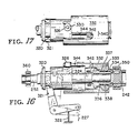
- Fig. 16 is a schematic fragmentary side elevation of another embodiment of a detector.
- Fig. 17 is a fragmentary plan of the device shown in Fig. 16.
- As shown in Fig. 1, a hoist system includes an
operating brake 2 coupled to a motor shaft 2a which is powered by amotor 3. A coupling 4 couples the motor to a conventional gear reduction unit 5, such as a 500:1 reduction, which has an output shaft 7 rotatably carried in a pillow block 8. Adrum pinion 9 meshes with thedrum gear 10. - A drum 11 is rotated by the drum gear on a shaft 11a a which is rotatably supported in a pair of spaced
pillow blocks 13. The hoist system is provided with a second brake, such as aband brake 14, wrapped on abrake drum 12. A brake-applying assembly orbrake actuator 15 will set the brake in response to a detected failure or other hazard condition. - A torque limiter assembly 6 is provided to limit the torque which would be imposed from high-speed rotational kinetic energy of the motor and high-speed drive elements of the gear reduction and motor drive if a load hang-up, overload or two-blocking occurs.
- A mechanical differential, out-of-
sync detector 20 is provided for detecting the failure or hazard condition. In one embodiment, the detector also provides the mechanical force for applying theband brake 14. In preferred embodiments, the detector merely signals the out-of-sync detection and a separate brake actuator sets the brake, as in Figs. 7 and 8. The out-of-sync detector 20 includes afirst input shaft 30 which is coupled to the motor shaft 2a by a right angle drive 19 having a gear reduction equivalent to that of the total gear reduction between the motor and the drum. A right angle drive 18 also couples the drum shaft 11 a to asecond input shaft 31 to thedetector 20. The purpose of the gear reduction in right angle drive 19 is to bring the two input shafts entering the dectector to approximately the same speed. Other forms of speed reduction can also be provided. - Each of the
input shafts 30, 31 (Fig. 3), is keyed to a drive gear which meshes with aside gear 26. Theside gears 26 are keyed topinion gears 27 that mesh with a planetary gear 27a of aplanet carrier 28. Equal and opposite rotational velocities of theinput shafts pin 46 to anoutput shaft 29 carried inbearings 25. Should the rotational velocity on either of the input shafts vary, an angular velocity will be created in theoutput shaft 29, the speed of which will depend on the relative variation between the velocities of the two input shafts. Thus, for example, if one of the input shafts should stop completely, the rotational output of theoutput shaft 29 will immediately reach a maximum speed. It is this rotation of the output shaft which triggers the brake actuation and, in one embodiment, creates or generates the force necessary for applying the brake on thebrake drum 12. It is possible to place this brake on a downstream pinion shaft in close proximity to the drum rather than directly on the drum. The purpose of this brake is to apply a stopping force on the drum as close to the drum as is practicable so that no substantial risk occurs from a failure of some drive element between the brake and the drum. Furthermore, theinput shaft 31 to the detector could also be from any location in the drive train between the motor and drum, which location is at the desired point to be monitored. Preferably, this location, however, will be at or close to the drum. - A
brake actuator mechanism 15 in Fig. 1 includes a lever 16a keyed to an extension 29a ofshaft 29. The lever is coupled to the free end of thebrake band 14 such that rotation of the lever 16a in either direction will set the band brake. The lever 16a is provided with anotch 16b in which is inserted a spring-centeredcog 17. A clutch 32couples shaft 29 to its extension 29a. A clutch throw outbar 33 follows acam 34 on the drum to decouple the shaft extension 29a once each rotation of the drum. If theshaft 29 rotates through some predetermined maximum angle, as, for example, because of differences in the speed reductions between the motor and drum and the speed reductions between the motor and drum anddetector 20 or because of creep in the drive train, lever 16a will rotate toward the maximum angle, but the clutch 32 will decouple the lever 16Q before it rotates far enough for the cog to leave thenotch 16b. Thus each time the clutch is decoupled at each complete revolution of the drum, the lever is returned to its centered position by thecog 17. In the event of a failure or load hang-up, etc., however, theshaft 29 will rotate at a high velocity and the drum will be stopped before one or perhaps at the most two more revolutions of the drum are possible. - The torque-limiting device 6 generally has a driven
gear 40 which is driven by one of the upper stages of the gear reduction in the gear case 5. Thegear 40 is provided with clutch facing 39 which is splined, as at 41, to ashaft 42. A spring 37 pushes apressure plate 38 against the clutch facing, thus releasably holding thegear 40 in driving engagement with theshaft 42. Apinion gear 44 is fixed to theshaft 42 by a key 45. By adjusting the position of thespring holder 36, a desired torque can be carried between the clutch facing and the drivengear 40. If an overload occurs, such as by excessive load, load hang-up, two-blocking, a jamming in the drive train, or the like, the high-speed kinetic energy upstream of the drivengear 40 will be dissipated as heat in the clutch facing and the downstream drive components frompinion gear 44 to the drum will be stopped. Because of this safety feature of the torque-limiting device, however, there may be a certain minimum amount of creep or relative rotational movement between thegear 40 and theshaft 36 so that there may be slight variations between theinput shaft 30 and thedrum input shaft 31 in thedifferential detector 20. - In one embodiment, a centrifugal clutch 47 (Fig. 5) is provided to decouple
input shaft 30 from motor shaft 2a when the motor shaft rotates at an overspeed above some pretermined percentage of its normal driven speed. That is, if some failure occurs which causes the motor to rotate beyond its set speed, theshaft 30 will become decoupled and stop, thus providing a variation between the relative velocities ofshaft 30 andshaft 31 to provide a rotational output tooutput shaft 29 and set the brake. It is important in the differential assembly that the differential rotation can not drive the input shafts backwards, and thus there are provided drag mechanisms on each of the input shafts to assure that only the output shaft is rotated when one of the input shafts changes its velocity relative to the other. Continuous friction drags could be provided on each of the shafts for this purpose, or the inputs could be through worm gear drives; but in the preferred embodiment, the shafts are broken into two sections, namely, an external section 31e and aninternal section 31i and an external section 30e and an internal section 30i. The internal and external sections of each shaft are joined by a conventional one-way clutch or "NO BAK" clutchingdevice 21. These devices are positioned so that the external section 30e, when driving in either direction, will freely rotate the internal section 30i. Likewise, the clutch on the drum input shaft is positioned so that when external section 31 e is providing a driving input, theinternal section 31i i will freely rotate. The converse is not true, however. That is, if at any time, one of the internal sections tries to drive the external section of that input shaft, the clutch will lock up so that the internal section cannot rotate. This provides a unique and more positive clutching or drag device for the input shafts to assure that when there is a change in velocity relative to the other input shaft, this change cannot be transmitted backwards to rotation of the other input shaft, but rather must be converted immediately and in all cases to a rotational output of theoutput shaft 29. - An overspeed clutch 47 is provided in a preferred embodiment. It is advantageous to employ a mechanical overspeed clutch having a
clutch friction plate 48 keyed to shaft 2a and an opposed friction andpressure plate 49 keyed to a separate stub shaft 50 which drives the right angle gear box 19. Aspring 52 is compressed bycentrifugal governor weights 54 to hold the friction plates in driving engagement. When shaft 2a rotates rapidly, as in an overspeed condition, theweights 54 swing outwardly andspring 52 is released, thereby allowingplates brake 14 is set. - Control systems for high-performance hoists are sometimes designed to sense the lifted load and to command
motor 3 to operate at higher than full-load rated speed when handling a lighter load. This may be as high as 300 percent when operating under such no-load condition. Conventional overspeed drives are generally set in this no-load case to cut out at more than 300 percent full-load speed. This reduces the safety when handling a full load. - Thus, if desired, the clutch 47 can also be made load-sensitive. To release the
friction discs bell crank 56 is threaded in anut 58 such that when screwed away fromspring 52, theweights 54 will have less pressure on them and will open to release thediscs - Motion of the bell crank 56 is provided by a
line 60 coupled to a pivotedarm 62 that is balanced by a calibratedspring 64. Thedrum line 70 is reaved about a travellingblock 72 and thence to asheave 73 onarm 62. As the load is increased,arm 62 is lowered, thus moving bell crank 56. - While the
detector 20 can signal an electrical shutoff or brake-setting device, it advantageously preferably signals or triggers a mechanical brake actuator. In the embodiment of Fig. 1, the detector can itself apply the brake. Two forms of triggering devices for setting thebrake 14 are illustrated in Figs. 7 and 8. It is common to both these triggering devices that a large spring force can be applied to set the brake, but a small trigger release force is all that is necessary to release the spring. - In Fig. 7, the
brake band 14 is set by aspring 74 having a large spring force, as is necessary for high-load capacity drums. Alever 75 is engaged by atrigger 76 which holds the spring in a cocked position. Thetrigger 76 is locked by a conventionaltrigger release cam 78. Asolenoid 80 having anextendible arm 81 pivotally mounts one end of thecam 78. The cam is also pivoted at 83 and has anend 84 that abuts thetrigger 76. Aspring 89 urges thecam 78 into the phantom-line position to disengage from thetrigger 76. Whensolenoid 80 is energized, the trigger release cam . is in the solid-line position. Thus it is apparent that the small, easily controlledspring 89 is all that must be overcome to hold thelarge spring 74 in the cocked position. - To reset the trigger and
spring 74, a relatively slow-speed rotary screw drive 90 moves the trigger, solenoid, and trigger release to the left. The trigger strikes a cam 92 that rotates the trigger counterclockwise, and the solenoid is energized to again hold the trigger in the cocked position. Movement of the screw to shift the trigger to the right then reengages thelever 75 and recompresses thespring 74. Since the spring can be compressed slowly, the highly leveraged screw drive is easily able to overcome very large spring forces. - Fig. 8 illustrates a mechanical trigger release. In this embodiment, the cam can be electrically de-energized without having to set the
brake 14, which is a disadvantage in the embodiment of Fig. 7. In this preferred embodiment, the lever 16a (Fig. 1), rather than being coupled directly to thebrake band 14, is coupled to an elongated cable 94that is connected to thetrigger release cam 78 by a lost-motion slot 95. As the lever 16a rotates in a out-of-sync condition, the cable 94 is pulled, pivotingtrigger release cam 78 into the phantom-line position to releasetrigger 76 in the same manner as in Fig. 7. Resetting of thespring 74,trigger 76, andcam 78 is similar to the above description of Fig. 7. - Fig. 3A illustrates a modification of the
detector 20 capable of providing a signal for setting a brake actuator. In this embodiment, thedetector output shaft 29 is provided with aflyball governor 97 that meshes with arack 98 slidably mounted in theshaft 29. As the ball lever swing out from an out-of-sync condition, teeth on the levers meshing with the rack extend the rack. The rack engages a normally closedswitch 99 to open the switch and de-energizesolenoid 80, for example, to set the brake. - If desired, a normally energized
electric clutch 100 can be added to any of the embodiments to decouple the motor shaft from the detector for setting the brake automatically if an electrical power failure occurs. Furthermore, this clutch or the overspeed clutch could also be placed on the drum side of the input to the differential detector. - The operation of the various embodiments of the safety system will now be described. During normal operaion, such as with the motor shaft 2a being rotated at approximately 1200 min the drum speed will be reduced to approximately 2.4 u/min at the drum shaft 11 a. The motor shaft at its 1200 u/min is then coupled through the centrifugal clutch 47 and right angle/gear reducer drive 19 to the differential
detector assem bly 20 via theinput shaft 30. Similarly, the 2.4 u/min rotation of the drum shaft is coupled via right angle drive 18 to provide the same It/min input to theinput shaft 31. It should be understood that these gear reductions do not have to be exact so long as they are proportionate, and the gear reduction, which is approximately 2:1 within the differential drive assembly, is sized accordingly. The desired result is thatshaft 31 andshaft 30, when the hoist is operating either in the lowering or hoisting mode, provide substantially the same angular velocities to the differential gear 27a so thatoutput shaft 29 rotates not at all or perhaps rotates one way or another at a very low rate, depending on the amount of slippage, variance in gear reductions, or creep in the system. If there is an overload, a load hang-up, a two-blocking or any failure in a drive component such that the drum tries to stop, the torque-limiting device will dissipate the high-speed kinetic energy in the motor and upstream drive components, and theinput shaft 31 will slow down or stop immediately, thus providing a variation between the angular velocities of theinput shaft 31 and theinput shaft 30. The motor input shaft will then cause theoutput shaft 29 to rotate rapidly; for example, at about 600 µ/min, since no slippage or back rotation can occur due to the clutch or drag 21 on the drum input shaft. Rotation of theoutput shaft 29 will immediately rotate theball governor 97 or rotate the lever 16a, and the force applied by this rotation will be used either as a signaling device, as in Figs. 7 and 8, to setthe brake, or, in a totally mechanical system, as in Fig. 1, to directly tighten the band brake. Should the motor shaft 2a rotate above its rated speed, such as where the controller may fail and allow the motor to drive the hoist too rapidly, the clutch 47 will disengage the motor shaft from the detector, stopping theinput shaft 30 and providing an out-of-sync rotation ofshaft 29. Similarly, if either theinput shaft 30 or theinput shaft 31 of the differential assembly should fail or any component in these inputs to the differential assembly should fail, theshaft 29 again will be rotated to set the brake. - In Fig. 9, in a preferred form of the invention a motor M is drivingly coupled to a drum D by a conventional power transmission main drive train including a
gear reduction unit 210 and a passiveenergy absorption device 212. - The opposite end of the motor M is connected through a secondary drive train to an
input shaft 214 of an out-of-sync detector 216 (Fig. 11). The motor M is joined to theinput shaft 214 by anelectric clutch 218 and right-angle drive element 219. The motor M is provided with an electrically controlledoperational brake 220, which is set when electrically de-energized, i.e., in the absence of electricity. Theelectrical clutch 218 is employed between the motor M and the motor input shaft 214foroverspeed protection. For this purpose, the clutch 218 is drivingly coupled between theinput shaft 214 and the motor when the electric motor is being energized, but becomes decoupled when the electricity is removed from the motor or during a total electrical blackout. The clutch also will become decoupled when the drum's rotational velocity exceeds a predetermined value, as in a hazard condition of the type in which the motor controller directs the motor to run at an unsafe overspeed condition. "Overspeed," as used herein, is a well known term in the art to signify a condition when, forthe particular hoisting system, the motor is running at an excessive speed, for example, 150 and 200 percent of its normal operating speed. - A
second input shaft 222 to thedetector 216 is coupled with the drum D. The drum is provided with asafety brake 224. The brake is set by abrake actuator 226 which recieves a signal from thedetector 216 of a failure or hazard condition, which signal is transmitted via amechanical cable 227. - The
detector 216 is provided with agear reduction 228 which couples thedrum shaft 222 to adifferential gear assembly 230 via a NO-BAK coupling 229 which will drivingly couple or transmit motion from theinput shaft 222 into the differential 230 in either rotational direction, but will lock up and not transmit motion in the reverse direction, that is, from thedifferential assembly 230 back to theinput shaft 222. - The
differential assembly 230 contains a set of bevel gears 236-239 which are freely rotatable on spindles that are keyed to ahousing 240. The housing is keyed to aspindle 242, whereasgears spindle 242. Clockwise rotation in the direction ofarrow 243 of thegear 236, with the housing held stationary, will result in counterclockwise rotation ofgear 238 in the direction ofarrow 244. If the entire housing rotates in a clockwise direction, as shown byarrow 245, then gear 238 will rotate, in a clockwise direction. (The rotational directions for purposes of this description will be viewed arbitrarily as looking in the direction of arrows 14-14 of Fig. 11, and also are arbitrarily shown as in the load lowering mode). -
Gear 238 is keyed to anoutput shaft 249 on which is mounted to a one-way sprag clutch 250. Theshaft 249 will freewheel in the counterclockwise direction of rotation in thesprag clutch 250, but in the opposite direction will lock up with the clutch, causing rotation of the clutch. - The input to the
differential housing 240 is through the NO-BAK clutch 229. The second input to the differential assembly is throughworm gear 251, driven by ascrew shaft 252.Worm gear 251 is keyed togear 236.Shaft 214 from motor M is connected toshaft 252 through a slip correction device 254 (Fig. 15). Theslip correction device 254 includes a first set ofgears shaft 252 than is inshaft 214.Gear 257 is coupled toshaft 252 through afriction slip clutch 258. A second set ofgears shaft 252 which is greater than the rotational velocity ofshaft 214.Gear 260 is coupled toshaft 214 through a one-way sprag clutch 263. The result of this gearing and clutching arrangement is that whenshaft 214 is turning counterclockwise (looking left in Fig. 15), for example, the drive will be throughgears shaft 252.Gear 260 will freewheel onshaft 214. Whenshaft 214 is rotated clockwise, sprag clutch 263locks gear 260, resulting inshaft 252 being rotated at a higher velocity thanshaft 214, withgear 257 slipping inclutch 258. The purpose of this slip correction device is to provide an input direction and velocity to the differential 230 which are different than those from the input from the NO-BAK 229 from the drum (assuming that the gear reductions between the drum and its differential input and the motor and the differential input throughgear 251 are at or about the same reductions) such thatgear 238 will always result in a net unidirectional rotation output in the counterclockwise direction. With the slip correction device, the counterclockwise component added to thegear 238 allows theoutput shaft 249 to rotate in a freewheeling condition; and should limited slip occur between the motor and the drum due to a passive energy absorption device, such asdevice 212, then the slip will be less than that required to trig the brake and the added component of velocity added to thegear 238 and will null out the slip during operation of the hoist. As a further example, assume that the motor is rotated in a direction to rotate the drum in a raising mode. For this description, assume that when raising,shaft 252 will be made to turn slower thanshaft 214. Also assume the teeth angles betweenscrew 252 andgear 251 are such that the input to the differential throughworm gear 251 will be faster but in the same direction as the input to the differential through NO-BAK 229. Assume these directions are counterclockwise. The net output will result in rotation ofshaft 249 in the counterclockwise direction. - When lowering the load, sprag clutch 263 becomes engaged and
shaft 252 is rotated at a greater speed thanshaft 214. This results in an input fromworm gear 251 to the differential assembly, which is greater than the input from NO-BAK 229. Since the direction of rotation of NO-BAK 229 is now in the opposite or clockwise direction, as shown byarrow 243, however, the net result will again produce an output rotation ofshaft 249 again in the counterclockwise, freewheeling direction. - Various examples of the operation for detection of a hazard or failure will now be given. As a first example, consider the drive between the motor and the drum via
gear reduction 210 is broken while the drum is being rotated in a raising mode. The drum will immediately reverse to a lowering mode, which will reverse the direction of the NO-BAK 229 but will not reverse the motor input direction. This will reverse the direction of thehousing 240, immediately causing a clockwise rotational direction toshaft 249 to produce a brake-set signal. - As a second example, consider two-blocking or load hang-up while the load is being raised. In this mode, the drum stops rotating; this stops rotation of the
differential housing 240. During normal operation in the raising direction,worm gear 251 was being rotated counterclockwise at a speed slower than thehousing 240, resulting in a net counterclockwise rotation ofshaft 249. However, when the NO-BAK 229 becomes stopped, then gear 238 is driven clockwise, which causesshaft 249 to engage withclutch 250 and produce a brake-set output. - As another example, consider a failure in the detector itself, for example, between the NO-
BAK 229 and theinput shaft 222 while raising a load. Since the NO-BAK transmits motion only when powered by theshaft 222, the NO-BAK will lock up upon failure of that drive. Thegear 238 will be moved in a clockwise direction, locking up clutch 250 to produce a brake-set. - As another type of failure, consider a failure in the detector itself when raising the load, such as by a failure of
shaft 252. As is well known, a worm gear cannot backdrive thescrew shaft 252. This locks up the input from the motor side of the differential, and thegear 238 will be driven in a clockwise direction to produce a brake-set signal as soon as the drum is reversed to the lowering mode. - In the case of overspeed in the down or lowering direction the clutch 218 will decouple, again stopping the
worm gear 251. The drum input will be the direction ofarrow 245, causing a clockwise direction ofshaft 249, and will set the brake. - The signal or clockwise movement of
sprag clutch 250 is provided to trigger release of the brake in a manner which allows the trigger to be reset without manual intervention. This is an advantage when testing an installed system as well as to reset the brake during inadvertent trips or when the brake has been set intentionally by a failure or by the operator of the hoist. This brake-actuating mechanism is best shown in Figs. 9, 10 and 11. In the embodiment illustrated, theband brake 224 is connected at its free end to abell crank 270. This bell crank is connected to atrigger mechanism 272 of a type similar to that shown in Figs. 7 and 8. Thetrigger mechanism 272 employs acatch 274 having a cam surface 276 and alower cam surface 278. Alatch 280 has anabutment end 282. The brake is set by a large force-applying compression spring, shown schematically as 284. The brake is retracted or reset by a conventional air bag or cylinder andpiston 286. The air bag is such that it is energized to compress the spring 284 and loosen the brake band. Theend 282 of thelatch 280 engages the cam surface 276. The latch is raised by engagement of aboss 288 on the backside of the catch. The arrangement of thecams 276 and 278 are such that they will try to rotatelatch 280 clockwise in a brake-releasing conditon, but so long as thelatch 280 is held in the upright condition, thecatch 274 cannot move. Thus, oncelatch 280 is held in the raised position, catch 274 cannot move and the air can be vented from theair bags 286. As a typical example, the force by the spring 284 will cause approximately 0,068 tons of force to be required to hold thelatch 280 in the raised position. This force is to be contrasted with the cocking force of several thousand pounds (2,72 tons, for example) that will be placed in the spring 284 by the air bags as is commonly necessary for setting this type of band brake. The advantage, of course, as with the embodiment of Figs. 1-8, is that a very quick acting, small restraining force can be used to trigger or release a much larger brake-applying force. - The upper end of
latch 280 is coupled by thecable 227 to aslide 292. The slide is held in a raised position by a smallerforce compression spring 294 of perhaps 10 to 15 Kp force. Theslide 292 is carried in atrack 295. The slide is held up by aroller 296 which is carried on awedge ring 298. The wedge ring is rotated counterclockwise by areset cable 300, which is coupled to atension spring 302. Due to the downward pull bycable 227,wedges 306 on the wedge ring lock into awedge carrier 307 that is fixed to thesprag clutch 250 in the position shown in solid lines in Fig. 14 (the operational position). In this condition, of course, theoutput shaft 249 from the differential will either be stationary or rotating in the counterclockwise direction so that the wedge ring freely rotates on theshaft 249. - When an output signal to set the brake is produced by clockwise rotation of the
output shaft 249, thesprag clutch 250 locks up and rotates clockwise. This clockwise rotation of the sprag clutch rotates thewedge ring 298 in the clockwise direction into the phantom line position of Fig. 14. This removesroller 296 from under theslide 292, allowing the force incable 290 to be released.Latch 280 is rotated clockwise, releasingcatch 274, allowing spring 284 to set the brake. - To reset the brake, air is applied to the
air bags 286, moving thecatch 274 to the left. Thecompression spring 294 raisesslide 292. Thereset spring 302 pullswedge ring 298 counterclockwise to reset the roller beneath the slide.Wedge ring 298 is slightly oversized on its shaft such that itswedges 306 release from thewedge carrier 307 when the downward load, caused bycable 227, is released from the wedge ring. This allows the wedge ring to be rotated into its reset condition or a counterclockwise direction. The resetting of theslide 292 and the wedge ring occurs prior to the time the air bags have retractedcatch 274 to its further left reset position. Thus the wedge ring remains free on clutch 250 until thelatch 280 is caused to rotate slightly clockwise by the spring 284 after the air bags have been vented. Then the small force is again applied to the slide to hold the wedge ring tight against the carrier and thus thesprag clutch 250. - Figs. 16 and 17 illustrate a simplified embodiment usable with
slip correction device 254. The differential detector of Fig. 16 employs amotor input shaft 252, from the motor and ahollow input shaft 242 from the drum. Acollar 320 is pivotally connected to abell crank 321. Aspring 322 holds the bell crank in a counterclockwise direction and is equivalent to thespring 294 of Fig. 14.Cable 227 is attached to the right-hand end of the bell crank. Thecollar 320 is keyed within anaxial slot 324 in theshaft 252. Aroller 326 is rotatably mounted on the collar. The roller is held against acam surface 330 which forms part of acam block 332. The cam block is joined toshaft 242 by afriction clutch 333 and a oneway clutch 338, positioned by needle thrust bearings 334 andradial bearings 337. The cam block freewheels on theshaft 242 in one direction of rotation, but is joined to theshaft 242 in locked arrangement by the one-way sprag clutch 338 andfriction clutch 333. The cam block moves with theshaft 242 and is held in the direction of thearrow 340 by acoil spring 342. Thecable 227 produces approximately a 0,068 tons pull on the collar, urging it axially to the right in Fig. 16, energizing thefriction clutch 333. As thecam block 332 is moved in the direction opposite to thearrow 340, the roller moves off thecam surface 330 and is pulled by the force incable 227 into aslot 344. This allows the bell crank to rotate clockwise, releasing the trigger to set the brake in the manner shown for the embodiment of Figs. 9-15. The friction clutch is also de-energized, allowingcam block 332 to freely rotate withshaft 252. Resetting of the brake is essentially the same as in the preferred embodiment, with thespring 322 moving the collar back to the left. This movement withdraws theroller 326 from theslot 344 and allowsspring 342 to reset the cam block in the direction of thearrow 340. Theroller 326 then is precluded from moving to the right in Fig. 16, which then holds the bell crank in a fixed position when the 0,068 tons load is again placed on thecable 227 by the trigger mechanism. - The device senses a differential movement between the
shaft 242 and theshaft 252 in a predetermined direction to cause thesprag clutch 338 to rotate clockwise in the embodiment illustrated to rotate the cam block and release thecollar 320. The normal operating rotations will produce either a zero differential rotation betweenshafts - Various examples of operation of the embodiment of Figures 16 and 17 will now be explained. In a first example, assuming the
motor input shaft 252 is turning clockwise and thedrum input shaft 242 is also turning clockwise, but because of the slip correction, theshaft 242 will be traveling clockwise slower thanwill shaft 252. In this condition, the sprag clutch is freewheeling. Theshaft 242 runs slower because the slip correction device is employed and thus the shaft is equivalent toshaft 252 of Fig. 15. There are also provided a NO-BAK 350locking shaft 242 to the frame and a NO-BAK 360locking shaft 252 to the frame. Thus NO-BAK 350 will allowshaft 242 to drive clockwise or counterclockwise, but will not allowshaft 242 to be driven byshaft 252. Similarly, NO-BAK 360 will allowshaft 252 to be driven from the motor but will not allowshaft 252 to backdrive through NO-BAK 360. Now assume that the motor shaft fails, creating a failure condition. NO-BAK 360locks shaft 252,shaft 242 thus turns clockwise faster thanshaft 252, clutch 338 engages, and thecam block 332 gets rotated clockwise, causingroller 326 to enterslot 344 and set the brake. - As a second example, consider raising the load, with the
motor input shaft 252 turning counterclockwise and thedrum shaft 242 turning counterclockwise. The slip correction device, however, will cause theshaft 242 to rotate faster thanshaft 252 in the counterclockwise direction such that the sprag clutch still freewheels. Again assume that there is a discontinuity in the main drive between the motor and the drum.Shaft 252 will lock up. The drum, since it was raising a load until the drive failure, will immediately reverse direction and begin to lower the load. Thus theshaft 242 will reverse to a clockwise direction, causing thecam block 332 to move clockwise and set the brake. - A further advantage is that whenever the operational brake is set, any slippage or failure in the operational brake will also be detected and set the safety brake. This overcomes a major problem in hoists because the brakes can otherwise wear severely without detection by the operator and allow the load to slip.
- As another example, assume a two-blocking hazard during raising.
Shaft 252 will be turning counterclockwise;shaft 242 will be turning counterclockwise.Shaft 242 will stop when the cable sheaves become two-blocked ("two-blocking" occurs when the traveling blocks engage the stationary blocks). Sinceshaft 242 is stopped and theshaft 252 continues to turn counterclockwise, theroller 326 moves off thecam surface 330 into the slot and sets the brake.
Claims (15)
Applications Claiming Priority (2)
| Application Number | Priority Date | Filing Date | Title |
|---|---|---|---|
| US20500980A | 1980-11-07 | 1980-11-07 | |
| US205009 | 1980-11-07 |
Publications (3)
| Publication Number | Publication Date |
|---|---|
| EP0064080A1 EP0064080A1 (en) | 1982-11-10 |
| EP0064080A4 EP0064080A4 (en) | 1985-07-01 |
| EP0064080B1 true EP0064080B1 (en) | 1988-05-25 |
Family
ID=22760411
Family Applications (1)
| Application Number | Title | Priority Date | Filing Date |
|---|---|---|---|
| EP19810903165 Expired EP0064080B1 (en) | 1980-11-07 | 1981-11-05 | Safety mechanism for hoisting drums |
Country Status (6)
| Country | Link |
|---|---|
| EP (1) | EP0064080B1 (en) |
| JP (1) | JPS57501680A (en) |
| CA (1) | CA1171069A (en) |
| DE (1) | DE3176754D1 (en) |
| ES (1) | ES506932A0 (en) |
| WO (1) | WO1982001700A1 (en) |
Cited By (1)
| Publication number | Priority date | Publication date | Assignee | Title |
|---|---|---|---|---|
| KR101329691B1 (en) | 2012-03-29 | 2013-11-14 | 주식회사 파워엠엔씨 | Single failure proof system for nuclear fuel handling device with perventing drop |
Families Citing this family (6)
| Publication number | Priority date | Publication date | Assignee | Title |
|---|---|---|---|---|
| JPS58113084A (en) * | 1981-12-28 | 1983-07-05 | 三菱電機株式会社 | Driving device |
| US4625946A (en) * | 1984-03-19 | 1986-12-02 | Ederer Incorporated | Hoist having worm safety device |
| CN107720581B (en) * | 2017-03-05 | 2023-04-28 | 郑州东辰科技有限公司 | Hand wheel and lever block and hoist device using same |
| US11377331B2 (en) | 2019-03-29 | 2022-07-05 | Goodrich Corporation | Automatic load brake having wear-induced locking mechanism |
| CN112623986B (en) * | 2020-12-24 | 2024-04-05 | 武汉钢铁集团宏信置业发展有限公司 | Rope winding type mine lifting device capable of rapidly switching anti-falling modes |
| CN117623130B (en) * | 2024-01-24 | 2024-04-09 | 中国建筑第五工程局有限公司 | Alarm device for construction hanging basket |
Family Cites Families (8)
| Publication number | Priority date | Publication date | Assignee | Title |
|---|---|---|---|---|
| US2250985A (en) * | 1939-07-08 | 1941-07-29 | Lidgerwood Mfg Co | Towing machine |
| US2356762A (en) * | 1942-02-09 | 1944-08-29 | Kalix John | Hoist |
| US2950086A (en) * | 1957-12-09 | 1960-08-23 | Nat Supply Co | Drilling control |
| US3102434A (en) * | 1959-10-16 | 1963-09-03 | Murphy Diesel Company | Automatic control of output reversal in slippable drives for transmitting torque |
| US3110199A (en) * | 1960-08-30 | 1963-11-12 | Lilly Arthur Richard | Hoist controller |
| US3753552A (en) * | 1971-03-25 | 1973-08-21 | Fyron Jackson Inc | Displacement control system for hoist apparatus |
| US4177973A (en) * | 1978-03-06 | 1979-12-11 | Ederer Incorporated | Cable drum safety brake |
| US4175727A (en) * | 1978-03-06 | 1979-11-27 | Ederer Incorporated | Single failure proof crane |
-
1981
- 1981-11-05 JP JP50000882A patent/JPS57501680A/ja active Pending
- 1981-11-05 EP EP19810903165 patent/EP0064080B1/en not_active Expired
- 1981-11-05 WO PCT/US1981/001481 patent/WO1982001700A1/en active IP Right Grant
- 1981-11-05 CA CA000389485A patent/CA1171069A/en not_active Expired
- 1981-11-05 DE DE8181903165T patent/DE3176754D1/en not_active Expired
- 1981-11-06 ES ES506932A patent/ES506932A0/en active Granted
Cited By (1)
| Publication number | Priority date | Publication date | Assignee | Title |
|---|---|---|---|---|
| KR101329691B1 (en) | 2012-03-29 | 2013-11-14 | 주식회사 파워엠엔씨 | Single failure proof system for nuclear fuel handling device with perventing drop |
Also Published As
| Publication number | Publication date |
|---|---|
| EP0064080A1 (en) | 1982-11-10 |
| ES8303235A1 (en) | 1983-02-01 |
| JPS57501680A (en) | 1982-09-16 |
| ES506932A0 (en) | 1983-02-01 |
| WO1982001700A1 (en) | 1982-05-27 |
| DE3176754D1 (en) | 1988-06-30 |
| CA1171069A (en) | 1984-07-17 |
| EP0064080A4 (en) | 1985-07-01 |
Similar Documents
| Publication | Publication Date | Title |
|---|---|---|
| US4493479A (en) | Hoist drive safety system | |
| CA1230063A (en) | Electric actuators | |
| US4175727A (en) | Single failure proof crane | |
| EP3045420B1 (en) | Safety brake for a lifting device | |
| JPS60209498A (en) | Hoist with worm safety device | |
| EP1661845B1 (en) | Hoisting gear and method for using the hoisting gear | |
| JPH0742070B2 (en) | Escalator spindle brake device | |
| EP0064080B1 (en) | Safety mechanism for hoisting drums | |
| EP0146281B1 (en) | Braking arrangement for a rotary drive system | |
| EP0433922B1 (en) | Brake mechanism for a storage and retrieval machine | |
| US4518153A (en) | Safety mechanism for hoisting drums | |
| EP2830986B1 (en) | Assembly comprising a security apparatus for equipping a lifting device, in particular a winch, and system for actuating said apparatus | |
| US5529157A (en) | Combination brake and clutch assembly for electric motors | |
| JPH07172778A (en) | Safe mechanism | |
| US4358088A (en) | Winch drive and braking mechanism | |
| US4245526A (en) | Mining machine haulage transmission | |
| JP2002068634A (en) | Emergency stopping device of elevator | |
| JP5930116B2 (en) | Elevating mechanism, in particular a safety device with a winch, and an assembly comprising a system for operating the device | |
| AU7896381A (en) | Safety mechanism for hoisting drums | |
| US2393120A (en) | Safety device in screw hoisting blocks | |
| FI71395C (en) | FRAMEWORK FOR THE ORIGINATION OF BEHAVIOR ROOMELSEN HOS EN AXEL | |
| US3918559A (en) | Camming mechanism for a brake or clutch device | |
| JPH05238680A (en) | Motor-driven hoisting device | |
| JPS6243980Y2 (en) | ||
| JPS641186Y2 (en) |
Legal Events
| Date | Code | Title | Description |
|---|---|---|---|
| PUAI | Public reference made under article 153(3) epc to a published international application that has entered the european phase |
Free format text: ORIGINAL CODE: 0009012 |
|
| AK | Designated contracting states |
Designated state(s): DE FR GB |
|
| 17P | Request for examination filed |
Effective date: 19821116 |
|
| GRAA | (expected) grant |
Free format text: ORIGINAL CODE: 0009210 |
|
| AK | Designated contracting states |
Kind code of ref document: B1 Designated state(s): DE FR GB |
|
| PG25 | Lapsed in a contracting state [announced via postgrant information from national office to epo] |
Ref country code: FR Free format text: THE PATENT HAS BEEN ANNULLED BY A DECISION OF A NATIONAL AUTHORITY Effective date: 19880525 |
|
| REF | Corresponds to: |
Ref document number: 3176754 Country of ref document: DE Date of ref document: 19880630 |
|
| EN | Fr: translation not filed | ||
| PLBE | No opposition filed within time limit |
Free format text: ORIGINAL CODE: 0009261 |
|
| STAA | Information on the status of an ep patent application or granted ep patent |
Free format text: STATUS: NO OPPOSITION FILED WITHIN TIME LIMIT |
|
| 26N | No opposition filed | ||
| PGFP | Annual fee paid to national office [announced via postgrant information from national office to epo] |
Ref country code: DE Payment date: 19931230 Year of fee payment: 13 |
|
| PG25 | Lapsed in a contracting state [announced via postgrant information from national office to epo] |
Ref country code: DE Effective date: 19950801 |
|
| PGFP | Annual fee paid to national office [announced via postgrant information from national office to epo] |
Ref country code: GB Payment date: 19961025 Year of fee payment: 16 |
|
| PG25 | Lapsed in a contracting state [announced via postgrant information from national office to epo] |
Ref country code: GB Free format text: LAPSE BECAUSE OF NON-PAYMENT OF DUE FEES Effective date: 19971105 |
|
| GBPC | Gb: european patent ceased through non-payment of renewal fee |
Effective date: 19971105 |