EP0063972B1 - Method and device for resource allocation in a system comprising autonomous data processing units - Google Patents
Method and device for resource allocation in a system comprising autonomous data processing units Download PDFInfo
- Publication number
- EP0063972B1 EP0063972B1 EP82400559A EP82400559A EP0063972B1 EP 0063972 B1 EP0063972 B1 EP 0063972B1 EP 82400559 A EP82400559 A EP 82400559A EP 82400559 A EP82400559 A EP 82400559A EP 0063972 B1 EP0063972 B1 EP 0063972B1
- Authority
- EP
- European Patent Office
- Prior art keywords
- unit
- signal
- source
- units
- logic
- Prior art date
- Legal status (The legal status is an assumption and is not a legal conclusion. Google has not performed a legal analysis and makes no representation as to the accuracy of the status listed.)
- Expired
Links
- 238000000034 method Methods 0.000 title claims description 52
- 238000012545 processing Methods 0.000 title claims description 9
- 238000013468 resource allocation Methods 0.000 title description 13
- 238000012546 transfer Methods 0.000 claims description 17
- 230000007704 transition Effects 0.000 claims description 16
- 230000000694 effects Effects 0.000 claims description 12
- 239000004020 conductor Substances 0.000 claims description 8
- 230000002457 bidirectional effect Effects 0.000 claims description 7
- 230000005540 biological transmission Effects 0.000 claims description 4
- 238000013475 authorization Methods 0.000 claims description 3
- 239000003990 capacitor Substances 0.000 claims description 3
- 230000004044 response Effects 0.000 claims description 3
- 230000003466 anti-cipated effect Effects 0.000 claims 2
- 230000003750 conditioning effect Effects 0.000 claims 1
- 238000001514 detection method Methods 0.000 claims 1
- 230000005764 inhibitory process Effects 0.000 claims 1
- 230000001902 propagating effect Effects 0.000 claims 1
- 239000004065 semiconductor Substances 0.000 claims 1
- 238000010586 diagram Methods 0.000 description 20
- 238000005516 engineering process Methods 0.000 description 15
- 230000006870 function Effects 0.000 description 10
- 230000004913 activation Effects 0.000 description 9
- 230000002093 peripheral effect Effects 0.000 description 7
- 230000008569 process Effects 0.000 description 6
- 230000001360 synchronised effect Effects 0.000 description 6
- 238000013459 approach Methods 0.000 description 5
- 230000000295 complement effect Effects 0.000 description 5
- 238000010200 validation analysis Methods 0.000 description 5
- 230000008859 change Effects 0.000 description 4
- 230000008878 coupling Effects 0.000 description 4
- 238000010168 coupling process Methods 0.000 description 4
- 238000005859 coupling reaction Methods 0.000 description 4
- 230000000630 rising effect Effects 0.000 description 4
- 230000001960 triggered effect Effects 0.000 description 4
- 230000006978 adaptation Effects 0.000 description 3
- 241000124892 Barbus Species 0.000 description 2
- 230000033228 biological regulation Effects 0.000 description 2
- 230000002950 deficient Effects 0.000 description 2
- 230000000737 periodic effect Effects 0.000 description 2
- 230000011664 signaling Effects 0.000 description 2
- 230000006641 stabilisation Effects 0.000 description 2
- 101100536354 Drosophila melanogaster tant gene Proteins 0.000 description 1
- 241001080024 Telles Species 0.000 description 1
- 240000008042 Zea mays Species 0.000 description 1
- 230000009471 action Effects 0.000 description 1
- 230000008901 benefit Effects 0.000 description 1
- 229940015273 buspar Drugs 0.000 description 1
- QWCRAEMEVRGPNT-UHFFFAOYSA-N buspirone Chemical compound C1C(=O)N(CCCCN2CCN(CC2)C=2N=CC=CN=2)C(=O)CC21CCCC2 QWCRAEMEVRGPNT-UHFFFAOYSA-N 0.000 description 1
- 238000004364 calculation method Methods 0.000 description 1
- 238000013461 design Methods 0.000 description 1
- 238000011161 development Methods 0.000 description 1
- 230000008014 freezing Effects 0.000 description 1
- 238000007710 freezing Methods 0.000 description 1
- 230000003993 interaction Effects 0.000 description 1
- 150000002500 ions Chemical class 0.000 description 1
- 238000004519 manufacturing process Methods 0.000 description 1
- 230000007246 mechanism Effects 0.000 description 1
- 230000004048 modification Effects 0.000 description 1
- 238000012986 modification Methods 0.000 description 1
- 210000000056 organ Anatomy 0.000 description 1
- 230000002441 reversible effect Effects 0.000 description 1
- 238000012552 review Methods 0.000 description 1
- 238000011105 stabilization Methods 0.000 description 1
- 230000003068 static effect Effects 0.000 description 1
- 230000009897 systematic effect Effects 0.000 description 1
- 238000012360 testing method Methods 0.000 description 1
- 230000009466 transformation Effects 0.000 description 1
- 238000000844 transformation Methods 0.000 description 1
- 210000003462 vein Anatomy 0.000 description 1
Images


Classifications
-
- G—PHYSICS
- G06—COMPUTING; CALCULATING OR COUNTING
- G06F—ELECTRIC DIGITAL DATA PROCESSING
- G06F13/00—Interconnection of, or transfer of information or other signals between, memories, input/output devices or central processing units
- G06F13/14—Handling requests for interconnection or transfer
- G06F13/36—Handling requests for interconnection or transfer for access to common bus or bus system
- G06F13/368—Handling requests for interconnection or transfer for access to common bus or bus system with decentralised access control
- G06F13/374—Handling requests for interconnection or transfer for access to common bus or bus system with decentralised access control using a self-select method with individual priority code comparator
Definitions
- the present invention relates to a method for allocating a resource in a system comprising autonomous data processing units, as well as to the device for implementing this method according to the preambles of claims 1 and 8.
- the term "data processing unit” must be understood in its most general acceptance.
- the systems comprising such units can be, by way of nonlimiting examples, automata such as digital machine tools comprising units performing specific tasks under the control of a program, regulation systems such as regulation systems road traffic comprising geographically distant peripheral units and processors or, more conventionally, computer systems.
- automata such as digital machine tools comprising units performing specific tasks under the control of a program
- regulation systems such as regulation systems road traffic comprising geographically distant peripheral units and processors or, more conventionally, computer systems.
- there are numerous problems of interactions between the various units In particular, when two or more units compete for access to the same resource, this type of conflict must be resolved optimally.
- a mass memory can constitute an example of a resource, this resource being made available to several autonomous processors.
- This process must meet many criteria. It must, for example, allow the parallel work of specialized units or accommodate between them units of technology and / or different families, in particular having different work cycles from each other. Another important condition to be satisfied is the harmonious adaptation of each unit to the overall workload of the system, also taking into account local particularities. This process must also allow a change in the configuration of the system, for example its extensibility, without requiring significant transformations.
- the first known methods made it possible to allocate resources according to priorities distributed according to a fixed hierarchical diagram or even according to a cyclical time distribution, under the control of fully centralized means.
- BUS REQUESTS a bundle of lines
- each line being associated with a priority level.
- the unit positions a particular signal on the line which corresponds to its priority level.
- BUS ASSIGNED a signal common to the units
- the bus allocation requesting units scan every conductors of said bundle to determine the highest priority request.
- the invention proposes to meet the needs which have been mentioned in the foregoing while avoiding the drawbacks of the prior art, in particular by fully decentralizing all the decision-making procedures for allocating a resource.
- the method of the invention makes it possible to minimize the loss of time at the time of the initial allocation of a resource or of the change in allocation of this resource.
- the subject of the invention is therefore a method of allocating a resource in a system comprising at least two autonomous data processing units, as specified in claim 1.
- a parallel European application published on 20-10-1982 under No. 63071, concerns a method of data transmission in a decentralized system.
- the invention also relates to a device for implementing this method as specified in claim 8.
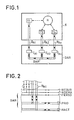
- a system S is represented schematically comprising several autonomous data processing units U 1 to Un. As has been recalled previously, these units can be of any kind. To fix the ideas, there will be described in the following a computer system S ′ comprising at least one data processor and peripheral units, without this being limiting the scope of the invention.
- a resource R which can be, for example, a data memory, to which one or more units U 1 to Un of the system S wish to have access.
- the invention proposes a device for allocating DAR resources comprising interface circuits I A1 to I An and a multiple link channel BAR for coupling between the interface means of the bus type.
- the units U 1 to Un of the system S are coupled by a particular bus B A1 to B An ' each to an interface circuit which is associated with it and which will be called in the following more briefly "interface”.
- these signals are of binary type and can therefore take two states: “0 or” 1 "logic.
- each unit is assigned a number or address and a priority level. This assignment can be carried out by any procedure of the known art, preferably dynamically.
- the assignment of the priority levels is carried out according to a diagram comprising a dynamic assignment of these levels.
- This assignment can be carried out using data recorded in a memory and preferably in a non-volatile memory of the “P.R.O.M.” type. (Programmable read-only memory).
- the priority level will be calculated using the difference between the numbers assigned to the active unit and to the unit requesting control of the resource to be allocated, according to a preferred variant.
- the resource is allocated to a so-called winning unit at the end of a "race" between the units in competition during which this winning unit will have posted the highest priority.
- the index i is an integer between 1 and n, n representing the number of units that can have access to a resource R of the system S.
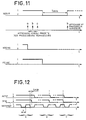
- FIG. 11 illustrates the case where three data processors a, b and c wish to acquire control of the same resource R.
- the start of the race is given by the descent of the signal “NCOUR” as indicated in the first line of the diagram in FIG. 11, caused simultaneously by the interfaces which first detected the triggering conditions. For each unit a new priority has been calculated before the falling edge "NCOUR". This priority is only displayed by the units (a, b, c) having positioned a request for the resource. After the necessary duration of propagation of the signals, the unit having presented the highest priority is allocated the resource. This also has the effect of reducing the “PERSO” signal to the low level (“logical 0”) and also prohibiting any new race.
- each data processing unit One has its own basic work cycle.
- these cycle times are different from each other. These times are defined by an internal clock or by clock signals derived from a centralized clock.
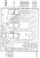
- Figure 2 shows in more detail the BAR bus connecting the interface circuits I A1 to I An . It includes three bidirectional link wires carrying the "NCOUR, NDEMA and PERSO" signals.
- N the first letter in the acronyms identifying the signals used by the present invention means that these signals are active in the low state or "logic 0".
- these signals and their meanings are recalled in TABLE I placed at the end of this description.
- the bus "BAR also comprises a channel with multiple bidirectional links" PRIO carrying a binary word displaying the level of the highest priority calculated by the interfaces I A1 to I An .
- this channel may include eight connecting wires, each carrying a bit, the priority word being composed of a byte.
- the bus “BAR also comprises a channel, also with multiple bidirectional links“ NACT •, comprising for example four wires for carrying a binary word of four bits representing the number of the winning processor (“b” in the example chosen) or more generally of the winning unit U i .
- the early launch of "NCOUR comes from the concern to take into account and satisfy as quickly as possible a request for resources, that is to say in practice a request to launch a race, if the request is made early enough.
- the winning unit is the only applicant in the S system, it will only take one clock cycle to resume the resource after a period of inactivity.
- this system is a computer system comprising different units: peripheral units and / or processors, all connected to a data exchange channel of the bus type.
- this channel constitutes a particularly interesting example of a resource to be allocated, for which the units are in competition.
- Figures 3 and 4 schematically illustrate such a system.
- the system S comprises a link channel “BUS for the exchange of data, this exchange being of the bidirectional type in the particular example described in relation to FIG. 3.
- this channel can include, as illustrated in FIG. 4, a bus conveying address words "ADR", for example thirty two bit words, a bus conveying data words "DON”, for example also thirty-two bit words divisible into bytes and a bus carrying "SPE" service signals. These generally include signals allowing secure exchanges such as validation and acknowledgment signals, as well as possibly clock and synchronization signals.
- This bus can also include ground links and links carrying the voltages necessary for the operation of the various units connected to it, depending on the nature of the technologies used.
- the precise architecture of the “BUS” link channel is outside the scope of the invention.
- the units U 1 to A component of the system can communicate with the channel "BUS using specific buses” BUS 1 "to" BUS n via interface circuits 1 D1 to Ion.
- These circuits have the role of carrying out all the necessary adaptations making it possible to connect a particular unit U i to the "BUS" channel, adaptations as it is known of a technological or software nature. These aspects also go beyond the scope of the present invention. It may also be necessary to synchronize with respect to each other the interface circuits for the allocation of resources (I Ai ) and the data exchange interface circuits (I Di ). This synchronization is symbolized by the links S y1 to S yn which can be multiple and include in particular clock signals.
- this peripheral unit or the winning processor takes control of the "BUS" channel, and can use this channel to exchange data with one or more other units, for example according to a procedure such as: addressing a particular unit followed by the exchange itself.
- the clocks of each unit can be used in association with a time base.
- the interface circuits (I Am ) for the allocation of the resources associated with each of the units in competition (Un) in a system S will now be described in more detail and an example of practical implementation will be given in the context of the approach which has just been recalled, that is to say when the resource to be allocated is a link channel for the exchange of data and the system S, a computer system.
- FIG. 5 schematically describes such an interface circuit. It is assumed first of all that each unit is provided with a clock, with a determined frequency delivering clock signals H i . These circuits are in the form of a module I Ai which is interconnected between the bus "BAR and the associated unit U i . It receives clock signals “2H i ” with a frequency twice that of the unit U i , these clock signals being synchronized with respect to each other. It is this clock which determines the minimum time of the run triggered by this interface IA i . The period must be greater than or equal to a minimum time to ensure proper functioning of the assembly, this time depending on the technology used.
- the interface I Ai is informed that the unit U i is requesting the channel "BUS for data exchange by the signal" DMB ".
- a signal “NSYNMEM” makes it possible to synchronize the interface I Ai with the data exchange interface l Di also associated with the unit U ,, as has been described in relation to FIGS. 3 and 4.
- This signal is one of the signals carried by the synchronization links (S yi ) shown in this same figure.
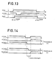
- the signal “NSYNMEM” represented on the first line of the diagram of FIG. 12, active at low level or “logic 0 according to the convention mentioned above, is a periodic signal of duration“ T ”at active level, duration equal to the time necessary for data transfer on the "BUS" channel. It only interferes with the operation of the interface I Ai at the time of the last data transfer carried out.
- Part C of the diagram in FIG. 12 represents the case where a faulty operation has appeared: the “ACTIVE” signal fell before the last transfer to be made.
- a “TIMEOUT” signal sets the maximum time associated with the unit U i for mastering the “BUS” channel. This time is determined using a capacitor C for example, of a determined value acting on a monostable as will be described later. Any other method can be implemented, for example a purely digital method using binary counters with modifiable capacity or associated with a logic for selecting a particular state.
- the unit In response to the “TIMEOUT” signal, the unit returns a “LIB releasing the interface signal.
- the interface receives on the “NSTA” channel a binary word representing the number assigned to the unit U i ,
- the interface I A1 can be broken down into four separate blocks which interconnect to carry out the allocation function as illustrated in FIG. 6.
- This part of the I AI interface is a decision-making body for the actions to be carried out on the "BUS" channel and on the "BAR" bus. Display of the request to participate in a possible race, display of the activity on the "BUS” channel with the "PERSO” signal and control of the "TIMEOUT” signal.
- Logic gates performing the AND, OR, NON-AND and NON-OR logic functions will be used in the following in their usual acceptances and there is no need to describe them further. It will also be used inverters which aim to provide the logical complement of a binary signal present on their input.
- the high level is the logic "1”, represented in the context of the technology chosen by a voltage + 5V, the low level being the logic "0”, represented by a zero voltage.
- Type D flip-flops are also used, the configuration of which is useful to recall in more detail. This, as well as the truth table and the time diagram of such a flip-flop can be found among other publications, in the French book: "From wired logic to microprocessors by Bernard et al., In volume 1, chapter X.4, pages 136-138 (Editions Eyrolles; Paris; 1979).
- Such a flip-flop comprises a data input D, a clock input H, a prepositioning input Pr (“preset”), a reset input CI (“clear”) and two outputs: true Q and reverse Q .
- the Pr and CI inputs are asynchronous, and reset the flip-flop to “1” or “0” respectively, independently of the clock signals.
- the synchronous mode is defined by the data input D and the clock input H.
- the flip-flop copies the input D after the appearance of a rising edge of the clock signal applied to the input H, counts given a delay of taking into account, of the order of a few nanoseconds for the chosen technology.
- logic circuits whose outputs are connected in parallel on the lines constituting the bus "BAR are of the type known as” open collector ". Indeed, the low level must be preponderant compared to the high level.
- the logic elements necessary for the production of the circuits can be chosen from the commercially available integrated circuits.
- the priority election function can be represented in symbolic form by a block receiving and emitting in particular the signal "NVAIN".
- This signal is internal to the interface I Ai . It indicates that the requesting unit considers itself to have the highest priority after analyzing its priority by the signals carried on the "PRIO (0 to 7) bus.
- block 60 receives “NSTA” signals (0 to 3) representing the number assigned to the unit U i and the signals “DMB” and “VCARTE” produced by the unit U i or the other blocks of the interface I Ai which will be described in the following.
- a unit U i To claim control of the "BUS" channel, a unit U i must participate in the race which ends with the determination of a winner. Participation is represented by the signal "PART”, is activated when a request from the unit U i is made when the race has not yet started: signal "NCOUR at high level. The unit's participation is activated during the entire occupation time of the "BUS" channel: "DMB at high level.
- circuits operate continuously. They include a PRIOR-1: 700 memory of the PROM type which fixes the priority according to the processor number (static number) given by the bus "NSTA (NSTA-0 to NSTA-3) and the number of the last processor present on the channel "BUS" (active number) given by the bus "NACT" (NACT-0 to NACT-3).
- the memory 700 provides a four-bit code (a o -a 3 ) which fixes the relative priority of the unit at an instant t. This priority is a function of the difference between "NACT" and "NSTA".
- the input circuits of memory 700 corresponding to the bits of the "NACT" bus include inverters.
- the length of the binary words conveyed by the "NACT and" NSTA buses is given solely by way of nonlimiting illustration of the invention.
- the number “NST A can be supplied by a wired logic. It can indeed be permanently assigned to the unit U j . With four bits, sixteen units can be connected to the "BUS" channel.
- the content of the PRIOR-1: 700 memory is given by TABLE II placed at the end of this description.
- the output signals are identified by the symbols a o to a 3 .
- the table highlights the priority algorithm.
- the content of the memory may not be standard and thus respond to particular applications.
- the priority code output from memory 700: a o to a s assigned at an instant t, is used to send a second PRIOR-2: 701 memory also of the PROM type, which is selected when the unit is participating in the race ("PART" active).
- Level 0 corresponds to the lowest priority.
- the mechanism is implemented as follows: Each unit that can participate in the race imposes a “0” on lines 0 to 7 of the “PRIO” bus to inhibit all the priorities of the other lower level units, the low level being preponderant. As a result, the unit wins if its priority level is not obliterated by another unit.
- the unit U i having the highest priority activates the signal "NVAIN” indicating that it has the highest priority.
- “NVAIN” evolves over time depending on demand. It stabilizes during the race (interval T of the signal “NCOUR in FIG. 12).
- the signal "NVAIN is produced by a multiplexer 702 receiving on its inputs the outputs of the memory" PRIOR-2 “: 701 which correspond respectively to bits 0 to 6 of the binary word conveyed by the corresponding links of the bus" PRIO "(as well as 'at the respective outputs D 7 to D 1 of memory 701).
- the addressing of this multiplexer to make the choice between the inputs is carried out in the example considered by a binary word of three bits constituted by the outputs a o to a 2 of the memory "PRIOR-1": 700.
- the content of the memory "PRIOR-2": 701 is given by way of example in TABLE III placed at the end of this description.
- the outputs D 7 to D 1 respectively corresponding to the bits carried by the "PRIOR-0 to" PRIOR-6 • links.
- the output D o activates the multiplexer 702 (authorization input S).
- the addressing of the memory "PRIOR-2”: 701 is carried out using a five-bit word: a o , a 1 , a 2 , a 3 and "PRIO-7".
- This signal “PRIO-7 is produced from the output a 3 of the memory” PRIOR-1 ": 700 inverted by the inverter 713 and signals” DMB “and” NCOUR "according to the logic function performed by the inverters 703 , 704, the NON-AND logic gates 707 and 708, the AND logic gate 705 and the D type flip-flop: 706 interconnected as shown in Figure 7.
- the signal on the "true” output: Q is the signal "PART already described.
- block 60 receives the signal "VCARTE” which enables it to display its number on the bus "NACT”. To do this, four NAND logic gates (709 and 712) are activated by the signal "VCARTE” so as to transmit the signals present on the links of the bus "NSTA" representing the number assigned to the unit U i .
- FIG. 8 is described an example of a concrete embodiment of the block 61. Its purpose is to develop the signals "PERSO”, “NDEMA” and “TIMEOUT” already described. To do this, it receives the other blocks of the interface I Ai or of the associated unit U i of the following signals: "NCOUR”, “NVAINS” and its complement “NVAINS”, “ACTIVE”, “DMB as well as “2H i ” clock signals with a frequency twice that of the clock signals of the unit U i , as previously mentioned.
- a race is started if a unit is claimant and there is necessarily a winner.
- the “PERSO” signal is therefore disabled at the start of a race, as illustrated by the diagram in FIG. 14.
- the unit U i To obtain the "BUS” channel, the unit U i must activate the "NDEMA” line, especially if the "BUS" channel is busy. This line is activated until the unit has been satisfied.
- the active unit must withdraw its request on the BAR bus so that requests from other units can be taken into account.
- block 61 receives a signal "NVAINS which will be described later and a monostable 807 is triggered.
- the duration of the output signal is fixed by a capacitor C.
- the time “TIMEOUT” is signaled to the unit U i only if another unit has made a bus request (“NDEMA”).
- the output signals which have just been described are produced using the OR logic gates: 801; NAND: 802, 804, 805; NOR: 806, of the reverser 803 and the rocker of type D: 800 and of the monostable 808 interconnected as indicated on figure 8.
- the marks “0 and“ 1 ” represent logical states“ zero and “one” permanent , that is to say according to the conventions accepted in the above, respectively of the low and high states.
- FIG. 9 represents an example of a concrete embodiment of block 62 of FIG. 6. This block produces four signals: "NVAINS” and its complement “NVAINS”, “ACTIVE” and "VCARTE”.
- the activity of the unit U i is signaled by the signal "ACTIVE".
- the race must end with the election of a unit and the display of its number on the "NACT" bus.
- the D type flip-flop: 901 is reset to zero as soon as the race is finished: validation of the "NVAINS" signal.
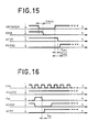
- the second case is that of early activation. This operating case is illustrated by the diagram in FIG. 16.
- the signal “VCARTE” in the high state indicates that the unit U i had last control of the channel “BUS”.
- the “NM” signal returns to the high state as soon as the “NCOUR” signal goes to the low state, thus indicating that the unit is master of the race.
- This signal is produced by block 63 which will be described later in connection with FIG. 10.
- the unit returns to the active state (“ACTIVE” signal in the high state), as soon as the first rising edge of the signals appears.
- “2H i ” clocks taking into account the time t M of taking this transition into account, which can be of the order of 20 ns. The unit therefore returns to activity before the end of the race (“NCOUR in the high state).
- the third case is where the unit takes control of the "BUS" channel while another unit had this control.
- the advance stroke function is used, the transfer of control from one unit to another takes place contiguously.
- This operating case is illustrated by the diagram in FIG. 17.
- control of the "BUS" channel passes, for example, from a processor referenced “a” to a processor "b", at the end of a race caused by the fallout of the “NCOUR” signal.
- the timing of the signals is clear from the diagram in Figure 17. It follows the procedures which have been described previously.
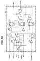
- the last block 63 is essentially intended to generate the race start signal "NCOUR” and incidentally the signal "NM”. To do this, it receives the signals "NDEMAN”, “ACTIVE”, “LIBR”, “DMB”, “PERSO and” NSYNMEN “as well as the clock signals" 2H i ".
- a race is launched each time one or more units (U 1 to Un) wish to access the "BUS" channel and obtain control over it.
- the race makes it possible to “freeze” requests in order to elect the highest priority unit.
- the signals “LIB” and “DMB” are produced by the unit U i associated with a given interface l Ai '
- the race begins on the first edge of the clock signal "2H i " after the fall of the signal "DMB". It ends at the end of the last transfer if a clock period has already elapsed.
- the minimum duration of a race is therefore equal to one period of the clock.
- the signal “NCOUR is produced using the signals transmitted to block 63 of FIG. 10 and which have been recalled using D type flip-flops: 1,001 to 1,003, AND-NO logic gates: 1,004, 1,010, 1012 and 1,013; AND: 1,005.1 1,006 and 1,015; OR: 1008 and 1016; and inverters 1 007, 1 009, 1 014, 1 011 and 1 017, interconnected as indicated in FIG. 10.
- the references “0” and “1” indicate two permanent states, low and high respectively.
- the “NCOUR” signal is only the complement of the copy of the “NM” signal. Otherwise, its duration (in the low state) is greater than that (high state) of the “NM” signal.
- the NAND AND 1013 logic gate is used to electrically decouple these two signals, the low state of the “NCOUR” signal on the corresponding link of the “BAR” bus being imposed by the interface producing the slowest NCOUR signal.
Landscapes
- Engineering & Computer Science (AREA)
- Theoretical Computer Science (AREA)
- Physics & Mathematics (AREA)
- General Engineering & Computer Science (AREA)
- General Physics & Mathematics (AREA)
- Bus Control (AREA)
- Multi Processors (AREA)
Description
La présente invention concerne un procédé d'allocation d'une ressource dans un système comportant des unités de traitement de données autonomes, ainsi que le dispositif de mise en oeuvre de ce procédé selon les préambules des revendications 1 et 8.The present invention relates to a method for allocating a resource in a system comprising autonomous data processing units, as well as to the device for implementing this method according to the preambles of
Dans le cadre de l'invention, le terme « unité de traitement de données » doit être entendu dans son acceptation la plus générale. Les systèmes comprenant de telles unités peuvent être, à titre d'exemples non limitatifs, des automates tels que des machines outils numériques comportant des unités exécutant des tâches spécifiques sous la commande d'un programme, des systèmes de régulation tels que les systèmes de régulation du trafic routier comportant des unités périphériques et des processeurs géographiquement éloignés ou encore, de façon plus classique, des systèmes informatiques. Dans tous ces systèmes se posent de nombreux problèmes d'interactions entre les diverses unités. Notamment, lorsque deux unités ou plus sont en compétition pour avoir accès à une même ressource, ce type de conflit doit être résolu de façon optimale. Pour fixer les idées, dans un système informatique comportant plusieurs processeurs une mémoire de masse peut constituer un exemple de ressource, cette ressource étant mise à la disposition de plusieurs processeurs autonomes.In the context of the invention, the term "data processing unit" must be understood in its most general acceptance. The systems comprising such units can be, by way of nonlimiting examples, automata such as digital machine tools comprising units performing specific tasks under the control of a program, regulation systems such as regulation systems road traffic comprising geographically distant peripheral units and processors or, more conventionally, computer systems. In all these systems, there are numerous problems of interactions between the various units. In particular, when two or more units compete for access to the same resource, this type of conflict must be resolved optimally. To fix ideas, in a computer system comprising several processors a mass memory can constitute an example of a resource, this resource being made available to several autonomous processors.
Dans de nombreuses applications le besoin se fait donc sentir de mettre en oeuvre un procédé d'allocation de ressources souple et performant.In many applications there is therefore a need to implement a flexible and efficient resource allocation process.
Ce procédé doit satisfaire à de nombreux critères. Il doit, par exemple, permettre le travail en parallèle d'unités spécialisées ou accomoder entre elles des unités de technologie et/ou de familles différentes, en particulier ayant des cycles de travail différents les uns des autres. Une autre condition importante à satisfaire est l'adaptation harmonieuse de chaque unité à la charge globale de travail du système, tenant compte également de particularités locales. Ce procédé doit aussi permettre un changement de la configuration du système, par exemple son extensibilité, sans nécessiter de transformations importantes.This process must meet many criteria. It must, for example, allow the parallel work of specialized units or accommodate between them units of technology and / or different families, in particular having different work cycles from each other. Another important condition to be satisfied is the harmonious adaptation of each unit to the overall workload of the system, also taking into account local particularities. This process must also allow a change in the configuration of the system, for example its extensibility, without requiring significant transformations.
Enfin, il est également très important que la fiabilité du système soit maximale. Le fonctionnement défectueux d'une des unités ne doit pas influencer le fonctionnement des autres unités et notamment interdire l'accès à une ressource commune lorsque ces unités sont en compétition avec l'unité défectueuse. De façon plus générale, le fonctionnement du système doit être sûr et tous les blocages doivent être évités.Finally, it is also very important that the reliability of the system is maximum. The defective operation of one of the units must not influence the operation of the other units and in particular prohibit access to a common resource when these units are in competition with the defective unit. More generally, the functioning of the system must be safe and all blockages must be avoided.
De nombreux procédés d'allocation de ressources sont connus. Ces procédés incorporent le plus souvent des procédures d'attribution d'un niveau de priorité aux unités en compétition.Many methods for allocating resources are known. These methods most often incorporate procedures for assigning a level of priority to the units in competition.
Les premiers procédés connus permettaient une allocation des ressources en fonction de priorités réparties selon un schéma hiérarchique fixe ou encore selon une répartition temporelle cyclique, sous la commande de moyens entièrement centralisés.The first known methods made it possible to allocate resources according to priorities distributed according to a fixed hierarchical diagram or even according to a cyclical time distribution, under the control of fully centralized means.
Dans le cadre des systèmes informatiques précités, il est courant d'utiliser des moyens de liaison entre les unités du type bus. Ces bus constituent des exemples particulièrement intéressants de ressources mises à la disposition de plusieurs unités de traitement de données et pour lesquelles les conflits d'accès doivent être résolus par un dispositif d'allocation de la maîtrise du bus.In the context of the aforementioned computer systems, it is common to use connecting means between the bus type units. These buses are particularly interesting examples of resources made available to several data processing units and for which access conflicts must be resolved by an allocation device for bus control.
Pour ce type d'application des procédés d'allocation de ressources plus souples que ceux précédemment évoqués ont été proposés. Ces procédés mettent en jeu des procédures d'attribution dynamique de priorité ou encore des procédures d'échange d'une séquence de message du type « demande-validation et/ou acceptation », procédures plus connues sous la dénomination anglo-saxonne « hand-shake ». Des procédés de ce type sont décrits dans les demandes de brevet français publiées sous les N° FR-A-2 179 031 et FR-A-2 376 464. Bien qu'introduisant un plus grand degré de décentralisation dans la prise de décision d'allocation d'une ressource, il est encore nécessaire selon ces procédés de disposer d'un organe centralisé pour assurer un bon déroulement des procédures, que ce soit l'un des processeurs connectés au bus ou une unité spécialisée connue sous différentes dénominations telles que « moniteur de bus ou « arbitre de bus ».For this type of application, more flexible resource allocation methods than those previously mentioned have been proposed. These methods bring into play procedures for dynamic allocation of priority or procedures for exchanging a message sequence of the “request-validation and / or acceptance” type, procedures better known under the Anglo-Saxon name “hand- shake ". Processes of this type are described in the French patent applications published under No. FR-A-2 179 031 and FR-A-2 376 464. Although introducing a greater degree of decentralization in decision-making d allocation of a resource, it is still necessary according to these methods to have a centralized body to ensure the smooth running of the procedures, whether it is one of the processors connected to the bus or a specialized unit known by different names such as "Bus monitor or" bus arbiter ".
Il est également connu du brevet US-A-4 209 838 un système dans lequel il est fait usage d'un organe central de commande, appelé « Channel qui détermine, sur réception d'un signal de requête, une fenêtre de temps pour la résolution des priorités.It is also known from US-A-4,209,838 a system in which use is made of a central control member, called a "Channel which determines, on reception of a request signal, a time window for the priority resolution.
Il est enfin connu que la résolution des priorités puisse s'effectuer de façon décentralisée. L'article de synthèse de KENNETH et al : « A systematic approach to the design of digital bussing structures », paru dans « Fall Joint Computer Conference 1972 » ; pages 719-740, décrit parmi d'autres possibilités, une variante de la méthode du type connu sous la dénomination anglo-saxonne de « decentralized version of independent requests » (cf fig. 12), dérivée de la méthode « independent requests using a centralized bus control selon la page 723 (fig. 9).Finally, it is known that the resolution of priorities can be carried out in a decentralized manner. The review article by KENNETH et al: "A systematic approach to the design of digital bussing structures", published in "Fall Joint Computer Conference 1972"; pages 719-740, described among other possibilities, a variant of the method of the type known by the Anglo-Saxon designation of "decentralized version of independent requests" (cf. fig. 12), derived from the method "independent requests using a centralized bus control according to page 723 (fig. 9).
Selon la méthode décrite, il est utilisé un faisceau de lignes, (« BUS REQUESTS »), chaque ligne étant associée à un niveau de priorité. Lorsqu'une unité désire l'utilisation du bus de transmission commun aux unités, l'unité positionne un signal particulier sur la ligne qui correspond à son niveau de priorité.According to the method described, a bundle of lines is used ("BUS REQUESTS"), each line being associated with a priority level. When a unit wishes to use the transmission bus common to the units, the unit positions a particular signal on the line which corresponds to its priority level.
Il est également utilisé un signal commun aux unités (« BUS ASSIGNED ») des unités est active. Lors de la retombée de ce signal, les unités demanderesses de l'allocation du bus scrutent tous les conducteurs dudit faisceau pour déterminer la demande présentant la plus haute priorité.It is also used a signal common to the units ("BUS ASSIGNED") of the units is active. When this signal drops out, the bus allocation requesting units scan every conductors of said bundle to determine the highest priority request.
L'invention se propose de répondre aux besoins qui ont été évoqués dans ce qui précède tout en obviant les inconvénients de l'art connu, notamment en décentralisant entièrement toutes les procédures de prise de décision d'allocation d'une ressource. En outre le procédé de l'invention permet de minimiser les pertes de temps au moment de l'attribution initiale d'une ressource ou du changement d'affectation de cette ressource.The invention proposes to meet the needs which have been mentioned in the foregoing while avoiding the drawbacks of the prior art, in particular by fully decentralizing all the decision-making procedures for allocating a resource. In addition, the method of the invention makes it possible to minimize the loss of time at the time of the initial allocation of a resource or of the change in allocation of this resource.
L'invention a donc pour objet un procédé d'allocation d'une ressource dans un système comportant au moins deux unités de traitement de données autonomes, tels que spécifié dans la revendication 1.The subject of the invention is therefore a method of allocating a resource in a system comprising at least two autonomous data processing units, as specified in
Une demande Européenne parallèle, publiée le 20-10-1982 sous le N° 63071, concerne un procédé de transmission de données dans un système décentralisé.A parallel European application, published on 20-10-1982 under No. 63071, concerns a method of data transmission in a decentralized system.
L'invention a encore pour objet un dispositif de mise en oeuvre de ce procédé tel que spécifié dans la revendication 8.The invention also relates to a device for implementing this method as specified in claim 8.
L'invention sera mieux comprise et d'autres avantages apparaîtront à l'aide de la description qui suit. en référence aux figures annexées :
- la figure 1 représente schématiquement un dispositif d'allocation de ressources selon l'invention ;
- la figure 2 représente plus en détail un des organes de la figure 1 ;
- la figure 3 est une variante du dispositif de la figure 1 dans laquelle la ressource allouée est un canal d'échange de données du type bus ;
- la figure 4 représente plus en détail le canal d'échange de données de la figure 3 ;
- la figure 5 représente schématiquement des moyens d'interface utilisés dans le dispositif d'allocation de ressource selon l'invention ;
- les figures 6 à 10 illustrent un exemple de réalisation pratique des moyens d'interface de la figure 5 ;
- les figures 11 à 18 sont des diagrammes illustrant le fonctionnement du dispositif de l'invention.
- FIG. 1 schematically represents a device for allocating resources according to the invention;
- Figure 2 shows in more detail one of the bodies of Figure 1;
- Figure 3 is a variant of the device of Figure 1 in which the allocated resource is a bus type data exchange channel;
- Figure 4 shows in more detail the data exchange channel of Figure 3;
- FIG. 5 schematically represents interface means used in the resource allocation device according to the invention;
- Figures 6 to 10 illustrate a practical embodiment of the interface means of Figure 5;
- Figures 11 to 18 are diagrams illustrating the operation of the device of the invention.
Le procédé de l'invention va être décrit dans sa généralité à l'aide des figures 1 et 2 et du diagramme de la figure 11.The process of the invention will be described in general with the aid of FIGS. 1 and 2 and the diagram of FIG. 11.
Sur la figure 1, est représenté schématiquement un système S comportant plusieurs unités autonomes de traitement de données U1 à Un. Comme il a été rappelé précédemment, ces unités peuvent être de toutes natures. Pour fixer les idées, il sera décrit dans ce qui suit un système informatique S' comprenant au moins un processeur de données et des unités périphériques, sans que cela soit limitatif de la portée de l'invention.In FIG. 1, a system S is represented schematically comprising several autonomous data processing units U 1 to Un. As has been recalled previously, these units can be of any kind. To fix the ideas, there will be described in the following a computer system S ′ comprising at least one data processor and peripheral units, without this being limiting the scope of the invention.
Il est représenté également sur la figure 1 une ressource R qui peut être, par exemple, une mémoire de données, à laquelle une ou plusieurs unités U1 à Un du système S désirent avoir accès.Also shown in FIG. 1 is a resource R which can be, for example, a data memory, to which one or more units U 1 to Un of the system S wish to have access.
Pour résoudre les conflits d'accès l'invention propose un dispositif d'allocation de ressources DAR comprenant des circuits d'interfaces IA1 à IAn et un canal de liaisons multiples BAR de couplage entre les moyens d'interface du type bus. Les unités U1 à Un du système S sont couplées par un bus particulier BA1 à BAn' chacune à un circuit d'interface qui lui est associé et qui sera appelé dans ce qui suit plus brièvement « interface ».To resolve access conflicts, the invention proposes a device for allocating DAR resources comprising interface circuits I A1 to I An and a multiple link channel BAR for coupling between the interface means of the bus type. The units U 1 to Un of the system S are coupled by a particular bus B A1 to B An ' each to an interface circuit which is associated with it and which will be called in the following more briefly "interface".
Selon l'une des caractéristiques les plus importantes de l'invention tous les circuits d'interfaces IA1 à IAn sont identiques, c'est-à-dire banalisés et le procédé d'allocation de ressources permet une décentralisation complète des décisions d'allocation.According to one of the most important characteristics of the invention, all of the interface circuits I A1 to I An are identical, that is to say trivialized, and the resource allocation method allows complete decentralization of the decisions of 'allocation.
Pour ce faire, il est utilisé un jeu de trois signaux fondamentaux :
- - un signal indiquant qu'il y a eu au moins une unité demandant à utiliser une ressource particulière R du système S. Dans ce qui suit ce signal sera appelé « NDEMA » ;
- - un signal signalant que cette ressource n'est sous le contrôle d'aucune unité, appelé « PERSO » ;
- - et un signal « NCOUR » d'une durée déterminée lançant la procédure d'attribution de la ressource à une des unités dite gagnante et figeant toutes autres demandes pendant la durée déterminée.
- - a signal indicating that there has been at least one unit requesting to use a particular resource R of the system S. In what follows this signal will be called “NDEMA”;
- - a signal indicating that this resource is not under the control of any unit, called "PERSO";
- - And a signal “NCOUR” of a determined duration launching the procedure of allocation of the resource to one of the so-called winning units and freezing all other requests during the determined duration.
De préférence, ces signaux sont de type binaire et peuvent donc prendre deux états : « 0 ou « 1 » logiques.Preferably, these signals are of binary type and can therefore take two states: "0 or" 1 "logic.
D'autre part, il est affecté à chaque unité un numéro ou adresse et un niveau de priorité. Cette affectation peut s'effectuer par toutes procédures de l'art connu, de préférence de façon dynamique.On the other hand, each unit is assigned a number or address and a priority level. This assignment can be carried out by any procedure of the known art, preferably dynamically.
La procédure de prise de la maîtrise d'une ressource se décompose en deux sous-procédures :
- - l'arbitrage entre plusieurs unités candidates à cette maîtrise ;
- - le transfert d'une unité à une autre de cette maîtrise après une période d'activité de l'unité qui en avait la maîtrise.
- - arbitration between several units applying for this master's degree;
- - the transfer from one unit to another of this mastery after a period of activity of the unit which had mastery.
Selon une variante préférée de l'invention, l'affectation des niveaux de priorités s'effectue selon un schéma comportant une affectation dynamique de ces niveaux. Cette affectation peut s'effectuer à l'aide de données enregistrées dans une mémoire et de façon préférentielle dans une mémoire non volatile de type « P.R.O.M. » (mémoire programmable à lecture seule). Le niveau de priorité sera calculé à l'aide de la différence entre les numéros attribués à l'unité en activité et à l'unité demanderesse de la maîtrise de la ressource à allouer, selon une variante préférée.According to a preferred variant of the invention, the assignment of the priority levels is carried out according to a diagram comprising a dynamic assignment of these levels. This assignment can be carried out using data recorded in a memory and preferably in a non-volatile memory of the “P.R.O.M.” type. (Programmable read-only memory). The priority level will be calculated using the difference between the numbers assigned to the active unit and to the unit requesting control of the resource to be allocated, according to a preferred variant.
La ressource est attribuée à une unité dite gagnante à l'issue d'une « course » entre les unités en compétition au cours de laquelle cette unité gagnante aura affichée la plus forte priorité.The resource is allocated to a so-called winning unit at the end of a "race" between the units in competition during which this winning unit will have posted the highest priority.
Une course est déclenchée dès que les trois conditions suivantes sont réunies :
- - « NDEMA actif (niveau bas ou « 0 » logique) signalant qu'au moins une unité Ui demande le contrôle de la ressource R ;
- - « PERSO » actif (niveau haut ou « 1 » logique) signalant que la ressource R n'est sous le contrôle d'aucune unité ;
- - « NCOUR » inactif (niveau haut) signalant qu'il n'y a pas une course en train de se dérouler.
- - “NDEMA active (low level or logical“ 0 ”) signaling that at least one unit U i requests control of the resource R;
- - “PERSO” active (high level or “1” logic) signaling that the resource R is not under the control of any unit;
- - “NCOUR” inactive (high level) indicating that there is not a race taking place.
L'indice i est un nombre entier compris entre 1 et n, n représentant le nombre d'unités pouvant avoir accès à une ressource R du système S.The index i is an integer between 1 and n, n representing the number of units that can have access to a resource R of the system S.
Le diagramme de la figure 11 illustre le cas où trois processeurs de données a, b et c désirent acquérir la maîtrise d'une même ressource R.The diagram in FIG. 11 illustrates the case where three data processors a, b and c wish to acquire control of the same resource R.
Le départ de la course est donné par la descente du signal « NCOUR » comme indiqué à la première ligne du diagramme de la figure 11, provoquée simultanément par les interfaces qui en ont, les premières, détectées les conditions de déclenchement. Pour chaque unité une nouvelle priorité a été calculée avant le front descendant « NCOUR ». Cette priorité n'est affichée que par les unités (a, b, c) ayant positionné une demande de la ressource. Après la durée de propagation des signaux nécessaire l'unité ayant présentée la plus forte priorité se voit attribuer la ressource. Cela a également pour effet de ramener le signal « PERSO » au niveau bas (« 0 » logique) et d'interdire aussi toute nouvelle course.The start of the race is given by the descent of the signal “NCOUR” as indicated in the first line of the diagram in FIG. 11, caused simultaneously by the interfaces which first detected the triggering conditions. For each unit a new priority has been calculated before the falling edge "NCOUR". This priority is only displayed by the units (a, b, c) having positioned a request for the resource. After the necessary duration of propagation of the signals, the unit having presented the highest priority is allocated the resource. This also has the effect of reducing the “PERSO” signal to the low level (“logical 0”) and also prohibiting any new race.
Dans le cadre d'un système informatique, chaque unité de traitement de donnée Un a un cycle de travail de base qui lui est propre. Lorsque les unités sont de technologies et/ou de familles différentes, ces temps de cycles sont différents les uns des autres. Ces temps sont définis par une horloge interne ou par des signaux d'horloge dérivés d'une horloge centralisée.In the context of a computer system, each data processing unit One has its own basic work cycle. When the units are of different technologies and / or families, these cycle times are different from each other. These times are defined by an internal clock or by clock signals derived from a centralized clock.
Après un temps Tmin déterminé par la plus lente des horloges des unités qui ont déclenché la course, le signal « NCOUR » est relevé et l'unité (b) gagnante affiche son numéro et signale le début de l'utilisation de la ressource par cette unité.After a time T min determined by the slowest of the clocks of the units which started the race, the signal “NCOUR” is raised and the winning unit (b) displays its number and signals the start of the use of the resource by this unity.
La figure 2 représente de façon plus détaillée le bus BAR reliant les circuits d'interfaces IA1 à IAn. Il comprend trois fils de liaisons bidirectionnelles véhiculant les signaux « NCOUR, NDEMA et PERSO ». Par convention, la lettre « N » comme première lettre dans les sigles repérant les signaux utilisés par la présente invention signifie que ces signaux sont actifs à l'état bas ou « 0 logique. Par ailleurs, ces signaux et leurs significations sont rappelés dans le TABLEAU I placé en fin de la présente description.Figure 2 shows in more detail the BAR bus connecting the interface circuits I A1 to I An . It includes three bidirectional link wires carrying the "NCOUR, NDEMA and PERSO" signals. By convention, the letter "N" as the first letter in the acronyms identifying the signals used by the present invention means that these signals are active in the low state or "
Le bus « BAR comprend d'autre part un canal à liaisons bidirectionnelles multiples « PRIO véhiculant un mot binaire affichant le niveau de la plus haute priorité calculée par les interfaces IA1 à IAn. Dans un exemple de réalisation particulière ce canal peut comprendre huit fils de liaison, véhiculant chacun un bit, le mot de priorité étant composé d'un octet.The bus "BAR also comprises a channel with multiple bidirectional links" PRIO carrying a binary word displaying the level of the highest priority calculated by the interfaces I A1 to I An . In a particular embodiment, this channel may include eight connecting wires, each carrying a bit, the priority word being composed of a byte.
Le bus « BAR comprend en outre un canal, également à liaisons bidirectionnelles multiples « NACT •, comprenant par exemple quatre fils pour véhiculer un mot binaire de quatre bits représentant le numéro du processeur vainqueur (« b » dans l'exemple choisi) ou plus généralement de l'unité gagnante Ui.The bus “BAR also comprises a channel, also with multiple bidirectional links“ NACT •, comprising for example four wires for carrying a binary word of four bits representing the number of the winning processor (“b” in the example chosen) or more generally of the winning unit U i .
Dans ce qui précède, il a été décrit le procédé de l'invention dans sa variante principale. Il est encore possible d'améliorer le procédé de l'invention par deux mesures particulières qui vont maintenant être détaillées : le lancement anticipé de la « course », c'est-à-dire essentiellement du signal « NCOUR et l'activation anticipée de cette « course ».In the foregoing, the method of the invention has been described in its main variant. It is still possible to improve the process of the invention by two specific measures which will now be described in detail: the early launch of the "race", that is to say essentially the signal "NCOUR and the early activation of this course ".
En ce qui concerne le lancement anticipé de la course, partant d'un état du système où la ressource R n'est pas active, c'est-à-dire non allouée, la procédure de prise de contrôle de cette ressource décrite dans ce qui précède ne permet pas de connaître les moments exacts de début et de fin d'une course. Tout au plus, chaque unité candidate sait-elle à quel moment elle-même déclenchera la course. De plus, dès la fin d'une course il devient possible qu'une nouvelle unité soit immédiatement validée. De là, une unité active qui désire quitter la ressource ne devrait autoriser une course, en relevant le signal « PERSO », qu'une fois terminé son dernier cycle. Or, si elle se trouve être candidate et gagnante de la nouvelle course, elle aura ainsi attendu inutilement un cycle avant de reprendre la ressource quittée. De plus, si le fonctionnement au niveau de la ressource est tel que chaque unité est active pendant une durée déterminée constante, il y a alors perte de temps due à l'élection du prochain vainqueur. Ces temps d'inactivité sont inacceptables. Il est souhaitable de pouvoir lancer une course en parallèle avec le dernier cycle de l'unité active, et de telle sorte que cette course se termine en même temps que ce cycle. Pour cela, l'unité active lance seule la course si, au cours de son dernier cycle elle aura détecté la présence d'une demande d'allocation de la ressource R. Il lui suffit de tester « NDEMA » sans relever le signal « PERSO •. Si aucune demande n'est en vue avant le front montant de son horloge défini sur son temps de cycle, elle relève le signal « PERSO » sur la fin du cycle pour quitter la ressource R et le cas normal décrit précédemment se répète. En libérant ainsi la ressource R sans avoir déclenché de course la dernière unité active y laisse cependant son numéro actif qui continuera à servir au calcul d'une nouvelle distribution de priorités pour la prochaine course.Regarding the early launch of the race, starting from a system state where the resource R is not active, that is to say unallocated, the procedure for taking control of this resource described in this the above does not allow to know the exact moments of start and end of a race. At most, each candidate unit knows when it will itself start the race. In addition, at the end of a race it becomes possible for a new unit to be immediately validated. From there, an active unit wishing to leave the resource should only authorize a race, by raising the “PERSO” signal, once its last cycle has ended. However, if she happens to be a candidate and winner of the new race, she will have waited unnecessarily for a cycle before taking up the resource left. In addition, if the operation at the resource level is such that each unit is active for a fixed fixed duration, then there is a loss of time due to the election of the next winner. These idle times are unacceptable. It is desirable to be able to start a race in parallel with the last cycle of the active unit, and in such a way that this race ends at the same time as this cycle. For this, the active unit only launches the race if, during its last cycle, it will have detected the presence of a request for allocation of the resource R. It suffices for it to test "NDEMA" without picking up the signal "PERSO •. If no request is in sight before the rising edge of its clock defined on its cycle time, it reads the signal "PERSO" at the end of the cycle to leave the resource R and the normal case described above is repeated. By thus freeing the resource R without having started a race, the last active unit leaves its active number there, which will continue to be used to calculate a new distribution of priorities for the next race.
En ce qui concerne la seconde mesure, le lancement anticipé de « NCOUR provient du souci de prendre en compte et de satisfaire le plus rapidement possible une demande de ressource, c'est-à-dire en pratique une demande de lancement de course, si la demande est présentée suffisamment tôt. Dans le même ordre d'idée, il est souhaitable que la validation d'une unité gagnante puisse aussi se faire au plus tôt. On risque en effet une perte de temps due à l'attente de la fin de la course pour la resynchronisation du vainqueur sur son horloge particulière.With regard to the second measure, the early launch of "NCOUR comes from the concern to take into account and satisfy as quickly as possible a request for resources, that is to say in practice a request to launch a race, if the request is made early enough. In the same vein, it is desirable that the validation of a winning unit can also be done as soon as possible. We risk indeed a loss of time due to the wait for the end of the race for the resynchronization of the winner on his particular clock.
On cherche donc, quand cela est possible, à valider l'unité gagnante sans attendre la fin de la course. Dans le cas où la dernière unité active est à nouveau demanderesse, elle peut, dès que sa course est terminée repasser en mode actif si elle est gagnante. Sachant qu'il n'existe qu'une seule unité gagnante à la fois, la validation anticipée ne nuit pas au bon fonctionnement du système.We therefore try, when possible, to validate the winning unit without waiting for the end of the race. In the event that the last active unit is again a plaintiff, it may, as soon as its course is finished go back to active mode if it wins. Knowing that there is only one winning unit at a time, early validation does not harm the proper functioning of the system.
Si l'unité gagnante est seule demanderesse dans le système S, elle ne mettra qu'un cycle d'horloge pour reprendre la ressource après une période d'inactivité.If the winning unit is the only applicant in the S system, it will only take one clock cycle to resume the resource after a period of inactivity.
Comme il a été rappelé, le procédé permet l'arbitration entre des unités demanderesses d'une ressource et l'allocation de cette ressource à une des unités de traitement autonomes d'un système S, quelque soit la nature de ce système. Dans une approche préférée, ce système est un système informatique comprenant différentes unités : unités périphériques et/ou processeurs, toutes reliées à un canal d'échange de données du type bus. Dans cette approche, ce canal constitue un exemple particulièrement intéressant de ressource à allouer, pour laquelle les unités sont en compétition. Les figures 3 et 4 illustrent schématiquement un tel système.As has been recalled, the method allows arbitration between requesting units of a resource and the allocation of this resource to one of the autonomous processing units of a system S, whatever the nature of this system. In a preferred approach, this system is a computer system comprising different units: peripheral units and / or processors, all connected to a data exchange channel of the bus type. In this approach, this channel constitutes a particularly interesting example of a resource to be allocated, for which the units are in competition. Figures 3 and 4 schematically illustrate such a system.
Outre le dispositif d'allocation de ressource « DAR » précédemment décrit, le système S comporte un canal de liaison « BUS pour l'échange de données, cet échange étant du type bidirectionnel dans l'exemple particulier décrit en relation avec la figure 3. De manière habituelle, ce canal peut comprendre comme illustrée sur la figure 4, un bus véhiculant des mots d'adresses « ADR », par exemple des mots de trente deux bits, un bus véhiculant des mots de données « DON », par exemple des mots également de trente deux bits divisibles en octets et un bus véhiculant des signaux de services « SPE ». Ces derniers comprennent généralement des signaux permettant des échanges sûrs tels que des signaux de validation et d'acquittement, ainsi qu'éventuellement des signaux d'horloges et de synchronisation. Ce bus peut également comprendre des liaisons de masse et des liaisons véhiculant les tensions nécessaires au fonctionnement des différentes unités qui lui sont connectées, selon la nature des technologies mises en oeuvre. L'architecture précise du canal de liaison « BUS sort du cadre de l'invention.In addition to the resource allocation device “DAR” previously described, the system S comprises a link channel “BUS for the exchange of data, this exchange being of the bidirectional type in the particular example described in relation to FIG. 3. Usually, this channel can include, as illustrated in FIG. 4, a bus conveying address words "ADR", for example thirty two bit words, a bus conveying data words "DON", for example also thirty-two bit words divisible into bytes and a bus carrying "SPE" service signals. These generally include signals allowing secure exchanges such as validation and acknowledgment signals, as well as possibly clock and synchronization signals. This bus can also include ground links and links carrying the voltages necessary for the operation of the various units connected to it, depending on the nature of the technologies used. The precise architecture of the “BUS” link channel is outside the scope of the invention.
Les unités U1 à Un composant le système peuvent communiquer avec le canal « BUS à l'aide de bus particuliers « BUS1 » à « BUSn via des circuits d'interfaces 1D1 à Ion. Ces circuits ont pour rôle d'effectuer toutes les adaptations nécessaires permettant de connecter une unité particulière Ui au canal « BUS », adaptations comme il est connu de nature technologique ou logicielle. Ces aspects sortent également du cadre de la présente invention. Il peut également être nécessaire de synchroniser l'un par rapport à l'autre les circuits d'interfaces pour l'allocation de ressources (IAi) et les circuits d'interfaces d'échange de données (IDi). Cette synchronisation est symbolisée par les liaisons Sy1 à Syn qui peuvent être multiples et comprendre notamment des signaux d'horloge.The units U 1 to A component of the system can communicate with the channel "BUS using specific buses" BUS 1 "to" BUS n via
Une fois l'unité périphérique ou le processeur vainqueur déterminé par le procédé de l'invention qui vient d'être décrit, cette unité périphérique ou ce processeur prend la maîtrise du canal « BUS », et peut utiliser ce canal pour échanger des données avec une ou plusieurs autres unités, par exemple selon une procédure comme du type : adressage d'une unité particulière suivi de l'échange proprement dit.Once the peripheral unit or the winning processor has been determined by the method of the invention which has just been described, this peripheral unit or this processor takes control of the "BUS" channel, and can use this channel to exchange data with one or more other units, for example according to a procedure such as: addressing a particular unit followed by the exchange itself.
Pour éviter une monopolisation du canal d'échange de données par une unité particulière, on peut allouer de façon centralisée ou de façon personnalisée un temps maximum au bout duquel la ressource, c'est-à-dire le canal « BUS dans cette approche, doit être remise en compétition et attribuée à nouveau selon le procédé de l'invention. Pour ce faire, les horloges de chaque unité peuvent être utilisées en association avec une base de temps.To avoid monopolization of the data exchange channel by a particular unit, it is possible to allocate, centrally or in a personalized manner, a maximum time at the end of which the resource, that is to say the "BUS" channel in this approach, must be put back into competition and allocated again according to the method of the invention. To do this, the clocks of each unit can be used in association with a time base.
Les circuits d'interface (IAm) pour l'allocation des ressources associés à chacune des unités en compétition (Un) dans un système S vont maintenant être décrits plus en détail et un exemple de réalisation pratique va en être donné dans le cadre de l'approche qui vient d'être rappelée, c'est-à-dire lorsque la ressource à attribuer est un canal de liaison pour l'échange de données et le système S, un système informatique.The interface circuits (I Am ) for the allocation of the resources associated with each of the units in competition (Un) in a system S will now be described in more detail and an example of practical implementation will be given in the context of the approach which has just been recalled, that is to say when the resource to be allocated is a link channel for the exchange of data and the system S, a computer system.
La figure 5 décrit schématiquement un tel circuit d'interface. Il est supposé tout d'abord que chaque unité est munie d'une horloge, d'une fréquence déterminée délivrant des signaux d'horloge Hi. Ces circuits se présentent sous la forme d'un module IAi qui s'interconnecte entre le bus « BAR et l'unité associée Ui. Il reçoit des signaux d'horloge « 2Hi » de fréquence double de celle de l'unité Ui, ces signaux d'horloge étant synchronisés l'un par rapport à l'autre. C'est cette horloge qui détermine le temps minimum de la course déclenchée par cet interface IAi. La période doit être supérieure ou égale à un temps minimum pour assurer un bon fonctionnement de l'ensemble, ce temps dépendant de la technologie utilisée.FIG. 5 schematically describes such an interface circuit. It is assumed first of all that each unit is provided with a clock, with a determined frequency delivering clock signals H i . These circuits are in the form of a module I Ai which is interconnected between the bus "BAR and the associated unit U i . It receives clock signals “2H i ” with a frequency twice that of the unit U i , these clock signals being synchronized with respect to each other. It is this clock which determines the minimum time of the run triggered by this interface IA i . The period must be greater than or equal to a minimum time to ensure proper functioning of the assembly, this time depending on the technology used.
Cinq signaux sont nécessaires pour relier l'interface à l'unité associée.Five signals are required to connect the interface to the associated unit.
L'interface IAi est averti que l'unité Ui est demanderesse du canal « BUS d'échange de données par le signal « DMB ».The interface I Ai is informed that the unit U i is requesting the channel "BUS for data exchange by the signal" DMB ".
Lorsque l'unité Ui est élue, l'interface IAi renvoie le signal « ACTIF indiquant que le canal « BUS est disponible et que les transferts de données peuvent commencer. Un signal « NSYNMEM » permet de synchroniser l'interface IAi avec l'interface d'échange de données lDi également associée à l'unité U,, comme il a été décrit en relation avec les figures 3 et 4. Ce signal est l'un des signaux véhiculés par les liaisons de synchronisation (Syi) représentées sur cette même figure. Le signal « NSYNMEM » représenté sur la première ligne du diagramme de la figure 12, actif au niveau bas ou « 0 logique selon la convention évoquée précédemment, est un signal périodique de durée « T » au niveau actif, durée égale au temps nécessaire à un transfert de donnée sur le canal « BUS ». Il n'interfère avec le fonctionnement de l'interface IAi qu'au moment du dernier transfert de données effectuées.When the unit U i is elected, the interface I Ai returns the signal "ACTIVE indicating that the channel" BUS is available and that the data transfers can begin. A signal “NSYNMEM” makes it possible to synchronize the interface I Ai with the data exchange interface l Di also associated with the unit U ,, as has been described in relation to FIGS. 3 and 4. This signal is one of the signals carried by the synchronization links (S yi ) shown in this same figure. The signal “NSYNMEM” represented on the first line of the diagram of FIG. 12, active at low level or “
Lorsque l'unité Ui libère le canal « BUS », elle a la possibilité d'indiquer quand va s'effectuer le dernier transfert. Pour cela, il suffit qu'elle fasse retomber le signal « DMB » alors que le signal « NSYNMEM » est encore actif. Ceci est représenté sur le diagrame de la figure 12, partie A.When the unit U i releases the "BUS" channel, it has the possibility of indicating when the last transfer. For that, it is enough that it makes fall the signal “DMB” while the signal “NSYNMEM” is still active. This is shown in the diagram in Figure 12, part A.
Si « DMB retombe lorsque « NSYNMEM » est inactif, l'interface IAi considère qu'il n'y aura plus de transferts. Ceci est représenté sur le diagramme de la figure 12, partie B.If “DMB drops when“ NSYNMEM ”is inactive, the interface I Ai considers that there will be no more transfers. This is shown in the diagram in Figure 12, part B.
Cette condition permet de réaliser le lancement anticipé de course qui a été évoqué précédemment et dont le déroulement détaillé sera décrit dans ce qui suit. Pour améliorer les performances, il est préférable d'utiliser cette fonction, auquel cas il faut s'assurer que le signal « DMB » est lié correctement au signal « NSYNMEM ».This condition makes it possible to carry out the early launch of the race which was mentioned previously and the detailed course of which will be described in the following. To improve performance, it is preferable to use this function, in which case it must be ensured that the “DMB” signal is correctly linked to the “NSYNMEM” signal.
Dans le cas général, la détermination du dernier transfert est sous la responsabilité de l'unité Ui en activité et sort du cadre de l'invention.In the general case, the determination of the last transfer is under the responsibility of the unit U i in activity and goes beyond the scope of the invention.
La partie C du diagramme de la figure 12 représente le cas où un fonctionnement défectueux est apparu : le signal « ACTIF » est retombé avant le dernier transfert à réaliser.Part C of the diagram in FIG. 12 represents the case where a faulty operation has appeared: the “ACTIVE” signal fell before the last transfer to be made.
Un signal « TIMEOUT » règle le temps maximum associé à l'unité Ui pour la maîtrise du canal « BUS ». Ce temps est déterminé à l'aide d'un condensateur C par exemple, d'une valeur déterminée agissant sur un monostable comme il sera décrit ultérieurement. Toute autre méthode peut être mise en oeuvre, par exemple une méthode purement numérique utilisant des compteurs binaires à capacité modifiable ou associés à une logique de sélection d'un état particulier.A “TIMEOUT” signal sets the maximum time associated with the unit U i for mastering the “BUS” channel. This time is determined using a capacitor C for example, of a determined value acting on a monostable as will be described later. Any other method can be implemented, for example a purely digital method using binary counters with modifiable capacity or associated with a logic for selecting a particular state.
Le signal « TIMEOUT permet de répartir les accès au canal « BUS ». Il peut être défini deux modes d'utilisation fondamentaux :
- - Le temps défini par le signal « TIMEOUT » a une valeur faible, par exempie de l'ordre de quelques microsecondes. Il permet alors à l'unité Ui de réaliser un à deux transferts de données sur le canal « BUS durant une activation de cette unité et de relâcher le canal « BUS » dès qu'il y a un autre demandeur. Dans ce cas chaque unité Ui accède au canal « BUS » souvent, mais pour peu de temps.
- - Le temps défini par le signal « TIMEOUT » est fixé de telle sorte qu'il soit de l'ordre de grandeur de la durée moyenne des accès au canal « BUS par t'unité Ui. Dans ce cas, l'unité Ui réalise en séquence une activité sur le canal « BUS ». Les temps morts sont également exploités.
- - The time defined by the "TIMEOUT" signal has a low value, for example of the order of a few microseconds. It then allows the unit U i to carry out one or two data transfers on the "BUS" channel during activation of this unit and to release the "BUS" channel as soon as there is another requester. In this case each unit U i accesses the "BUS" channel often, but for a short time.
- - The time defined by the "TIMEOUT" signal is fixed so that it is of the order of magnitude of the average duration of access to the "BUS" channel by the unit U i . In this case, the unit U i performs an activity in sequence on the "BUS" channel. Time-outs are also used.
En réponse au signal « TIMEOUT », l'unité renvoie un signal « LIB libérant l'interface.In response to the “TIMEOUT” signal, the unit returns a “LIB releasing the interface signal.
Enfin l'interface reçoit sur le canal « NSTA » un mot binaire représentant le numéro attribué à l'unité Ui,Finally, the interface receives on the “NSTA” channel a binary word representing the number assigned to the unit U i ,
L'interface IA1 peut être décomposé en quatre blocs distincts s'interconnectant pour réaliser la fonction d'allocation comme illustré par la figure 6.The interface I A1 can be broken down into four separate blocks which interconnect to carry out the allocation function as illustrated in FIG. 6.
On trouve successivement :
- - un circuit d'élection de priorité 60. Ce circuit contient la logique déterminant la priorité. Il émet un signal indiquant que le circuit se considère comme ayant le code de plus forte priorité sur le canal « BUS » : « NVAIN
- - un circuit de déclenchement de la
course 61. A partir d'informations externes : demande du canal « BUS », unité Ui gagnante, « NVAIN », etc. ; la logique associée à ce circuit détermine si la course peut être déclenchée et pilotée par le circuit lui-même lorsqu'il y a anticipation. Il émet deux signaux principaux : - - « NCOUR déjà décrit ;
et « NM qui indique que c'est l'unité Ui qui est maîtresse de la course.
- - le circuit d'activation de l'unité 62 qui a pour rôle essentiel d'avertir l'unité Ui que sa demande est satisfaite. L'activité cesse lorsque la demande disparait suivant les conditions qui viennent d'être précisées.
- - a
priority election circuit 60. This circuit contains the logic determining the priority. It emits a signal indicating that the circuit considers itself to have the highest priority code on the "BUS" channel: "NVAIN - - a circuit for triggering the
race 61. From external information: request from the "BUS" channel, winning unit U i , "NVAIN", etc. ; the logic associated with this circuit determines whether the race can be started and controlled by the circuit itself when there is anticipation. It emits two main signals: - - “NCOUR already described;
and “NM which indicates that it is the unit U i which is the master of the race.
- - The activation circuit of the
unit 62 which has the essential role of warning the unit U i that its request is satisfied. The activity ceases when the demand disappears under the conditions which have just been specified.
La logique associée à ce bloc renvoie vers le circuit d'élection de priorité le signal « VCARTE », permettant à l'unité Ui d'afficher son numéro sur le bus « NACT » et indiquer le numéro vainqueur.
- - le circuit de contrôle d'utilisation du canal « BUS » 63.
- - the control circuit for using the "BUS"
channel 63.
Cette partie de l'interface IAI est un organe de décision des actions à effectuer sur le canal « BUS et sur le bus « BAR ». Affichage de la demande pour participer à une éventuelle course, affichage de l'activité sur le canal « BUS par le signal « PERSO et contrôle du signal « TIMEOUT ».This part of the I AI interface is a decision-making body for the actions to be carried out on the "BUS" channel and on the "BAR" bus. Display of the request to participate in a possible race, display of the activity on the "BUS" channel with the "PERSO" signal and control of the "TIMEOUT" signal.
Le fonctionnement détaillé de ces différents blocs va maintenant être décrit et des exemples concrets de réalisation pratiques vont en être donnés.The detailed operation of these different blocks will now be described and concrete examples of practical implementation will be given.
Pour fixer les idées, le choix de la technologie mise en oeuvre peut se porter sur une technologie rapide de type « Schottky ».To fix the ideas, the choice of the technology implemented can be carried out on a fast technology of the “Schottky” type.
Il sera utilisé dans ce qui suit des portes logiques réalisant les fonctions logiques ET, OU, NON-ET et NON-OU dans leurs acceptations habituelles et il n'y a pas lieu de les décrire plus avant. Il sera également utilisé des inverseurs qui ont pour but de fournir le complément logique d'un signal binaire présent sur leur entrée. Par convention, le niveau haut est le « 1 » logique, représenté dans le cadre de la technologie choisie par une tension + 5V, le niveau bas étant le « 0 » logique, représenté par une tension nulle.Logic gates performing the AND, OR, NON-AND and NON-OR logic functions will be used in the following in their usual acceptances and there is no need to describe them further. It will also be used inverters which aim to provide the logical complement of a binary signal present on their input. By convention, the high level is the logic "1", represented in the context of the technology chosen by a voltage + 5V, the low level being the logic "0", represented by a zero voltage.
Il est aussi utilisé des bascules de type D, dont il est utile d'en rappeler la configuration plus en détail. Celle-ci, ainsi que la table de vérité et le diagramme de temps d'une telle bascule peuvent être trouvés parmi d'autres publications, dans le livre français : « De la logique câblée aux microprocesseurs par Bernard et autres, au tome 1, chapitre X.4, pages 136-138 (Editions Eyrolles ; Paris ; 1979).Type D flip-flops are also used, the configuration of which is useful to recall in more detail. This, as well as the truth table and the time diagram of such a flip-flop can be found among other publications, in the French book: "From wired logic to microprocessors by Bernard et al., In
Une telle bascule comporte une entrée de donnée D, une entrée d'horloge H, une entrée de prépositionnement Pr (« preset »), une entrée de remise à zéro CI (« clear ») et deux sorties : vraie Q et inversée
Il doit être noté que les circuits logiques dont les sorties sont connectées en parallèle sur les lignes constituant le bus « BAR sont du type dit à « collecteur ouvert ». En effet, il faut que le niveau bas soit prépondérant par rapport au niveau haut.It should be noted that the logic circuits whose outputs are connected in parallel on the lines constituting the bus "BAR are of the type known as" open collector ". Indeed, the low level must be preponderant compared to the high level.
Enfin, seules les fonctions logiques essentielles à la compréhension de l'invention seront décrites et représentées sur les figures 7 à 10. De même, les circuits annexes tels que les circuits de distribution d'alimentation électrique ne seront pas représentés.Finally, only the logic functions essential for understanding the invention will be described and shown in FIGS. 7 to 10. Likewise, the auxiliary circuits such as the electrical power distribution circuits will not be shown.
Les éléments logiques nécessaires à la réalisation des circuits peuvent être choisis parmi les circuits intégrés disponibles dans le commerce.The logic elements necessary for the production of the circuits can be chosen from the commercially available integrated circuits.
Comme le montre la figure 7 la fonction élection de priorité peut être représentée sous forme symbolique par un bloc recevant et émettant notamment le signal « NVAIN ». Ce signal est interne à l'interface IAi. Il indique que l'unité demanderesse se considère comme la plus prioritaire après analyse de sa priorité par les signaux véhiculés sur le bus « PRIO (0 à 7).As shown in FIG. 7, the priority election function can be represented in symbolic form by a block receiving and emitting in particular the signal "NVAIN". This signal is internal to the interface I Ai . It indicates that the requesting unit considers itself to have the highest priority after analyzing its priority by the signals carried on the "PRIO (0 to 7) bus.
Ces signaux sont reçus et réémis éventuellement après modification. Il en est de même pour les signaux représentant le numéro de l'unité active « NACT (0 à 3). Pour élaborer ces signaux, le bloc 60 reçoit des signaux « NSTA »(0 à 3) représentant le numéro attribué à l'unité Ui et les signaux « DMB » et « VCARTE » élaborés par l'unité Ui ou les autres blocs de l'interface IAi qui seront décrits dans ce qui suit.These signals are received and possibly retransmitted after modification. The same applies to the signals representing the number of the active unit "NACT (0 to 3). To develop these signals, block 60 receives “NSTA” signals (0 to 3) representing the number assigned to the unit U i and the signals “DMB” and “VCARTE” produced by the unit U i or the other blocks of the interface I Ai which will be described in the following.
Pour prétendre à la maîtrise du canal « BUS », une unité Ui doit être participante à la course qui se termine par la détermination d'un vainqueur. La participation est représentée par le signal « PART », est activée lorsqu'une demande de l'unité Ui est faite alors que la course n'a pas encore commencé : signal « NCOUR au niveau haut. La participation de l'unité est activée durant toute la durée d'occupation du canal « BUS » : « DMB au niveau haut.To claim control of the "BUS" channel, a unit U i must participate in the race which ends with the determination of a winner. Participation is represented by the signal "PART", is activated when a request from the unit U i is made when the race has not yet started: signal "NCOUR at high level. The unit's participation is activated during the entire occupation time of the "BUS" channel: "DMB at high level.
Ce fonctionnement est illustré par le diagramme de la figure 13.This operation is illustrated by the diagram in FIG. 13.
Ensuite le calcul des priorités relatives est effectué par les circuits du bloc 60.Then the relative priorities are calculated by the circuits of
Ces circuits fonctionnent en permanence. Ils comprennent une mémoire PRIOR-1 : 700 du type PROM qui fixe la priorité suivant le numéro du processeur (numéro statique) donné par le bus « NSTA (NSTA-0 à NSTA-3) et le numéro du dernier processeur présent sur le canal « BUS » (numéro actif) donné par le bus « NACT » (NACT-0 à NACT-3). La mémoire 700 fournit un code de quatre bits (ao-a3) qui fixe la priorité relative de l'unité à un instant t. Cette priorité est une fonction de la différence entre « NACT » et « NSTA ». Les circuits d'entrée de la mémoire 700 correspondant aux bits du bus « NACT » comportent des inverseurs.These circuits operate continuously. They include a PRIOR-1: 700 memory of the PROM type which fixes the priority according to the processor number (static number) given by the bus "NSTA (NSTA-0 to NSTA-3) and the number of the last processor present on the channel "BUS" (active number) given by the bus "NACT" (NACT-0 to NACT-3). The
La longueur des mots binaires véhiculés par les bus « NACT et « NSTA est donnée au seul titre d'illustration non limitative de l'invention. Le numéro « NSTA peut être fourni par une logique cablée. Il peut être en effet attribué de façon permanente à l'unité Uj. Avec quatre bits, seize unités peuvent être connectées au canal « BUS ».The length of the binary words conveyed by the "NACT and" NSTA buses is given solely by way of nonlimiting illustration of the invention. The number “NST A can be supplied by a wired logic. It can indeed be permanently assigned to the unit U j . With four bits, sixteen units can be connected to the "BUS" channel.
Toujours à titre d'exemple, le contenu de la mémoire PRIOR-1 : 700 est donné par le TABLEAU II placé en fin de la présente description. Les signaux de sortie sont repérés par les symboles ao à a3.Still by way of example, the content of the PRIOR-1: 700 memory is given by TABLE II placed at the end of this description. The output signals are identified by the symbols a o to a 3 .
Le tableau met en évidence l'algorithme de priorité. Le contenu de la mémoire peut ne pas être standard et ainsi répondre à des applications particulières.The table highlights the priority algorithm. The content of the memory may not be standard and thus respond to particular applications.
On peut obtenir un fonctionnement à priorité fixe, ou attribuer les priorités par groupe d'unités : unités périphériques et/ou processeurs.Fixed priority operation can be obtained, or priorities can be assigned by group of units: peripheral units and / or processors.
Dans ce cas, pour chaque groupe d'unités les priorités de ces unités sont relatives à l'intérieur du groupe mais les groupes ont une priorité fixe.In this case, for each group of units the priorities of these units are relative within the group but the groups have a fixed priority.
Lors de l'initialisation du système, l'unité à laquelle le numéro « NSTA » = 0000 a été attribué prend fictivement le contrôle du canal « BUS » et transmet sur le canal « NACT » le numéro « 1111 ». Elle sera ensuite la moins prioritaire quand le signal « PERSO est actif (niveau haut).During system initialization, the unit to which the number "NSTA" = 0000 has been fictitiously takes control of the "BUS" channel and transmits the number "1111" on the "NACT" channel. It will then have the lowest priority when the signal "CUSTOM is active (high level).
Le code de priorité, sorties de la mémoire 700 : ao à as attribué à un instant t, sert à adresser une seconde mémoire PRIOR-2 : 701 également du type P.R.O.M., qui est sélectionnée lorsque l'unité est participante à la course (« PART » actif). Le niveau 0 correspond à la plus basse priorité. Le mécanisme est réalisé comme suit :
Chaque unité pouvant participer à la course impose un « 0 » sur les lignes 0 à 7 du bus « PRIO » pour inhiber toutes les priorités des autres unités de niveau inférieur, le niveau bas étant prépondérant. De ce fait, l'unité est gagnante si son niveau de priorité n'est pas oblitéré par une autre unité.The priority code, output from memory 700: a o to a s assigned at an instant t, is used to send a second PRIOR-2: 701 memory also of the PROM type, which is selected when the unit is participating in the race ("PART" active).
Each unit that can participate in the race imposes a “0” on
L'unité Ui ayant la plus forte priorité active le signal « NVAIN » indiquant qu'elle est la plus prioritaire. « NVAIN » évolue dans le temps en fonction des demandes. Il se stabilise durant la course (intervalle T du signal « NCOUR de la figure 12). Le signal « NVAIN est produit par un multiplexeur 702 recevant sur ses entrées les sorties de la mémoire « PRIOR-2 » : 701 qui correspondent respectivement aux bits 0 à 6 du mot binaire véhiculés par les liaisons correspondantes du bus « PRIO » (ainsi qu'aux sorties respectives D7 à D1 de la mémoire 701). L'adressage de ce multiplexeur pour effectuer le choix entre les entrées s'effectue dans l'exemple considéré par un mot binaire de trois bits constitués par les sorties ao à a2 de la mémoire « PRIOR-1 » : 700.The unit U i having the highest priority activates the signal "NVAIN" indicating that it has the highest priority. "NVAIN" evolves over time depending on demand. It stabilizes during the race (interval T of the signal “NCOUR in FIG. 12). The signal "NVAIN is produced by a
Le contenu de la mémoire « PRIOR-2» : 701 est donné à titre d'exemple dans le TABLEAU III placé en fin de la présente description. Les sorties D7 à D1 correspondant respectivement aux bits véhiculés par les liaisons « PRIOR-0 à « PRIOR-6 •. La sortie Do active le multiplexeur 702 (entrée d'autorisation S). L'adressage de la mémoire « PRIOR-2 » : 701 est réalisé à l'aide d'un mot de cinq bits : ao, a1, a2, a3 et « PRIO-7 ». Ce signal « PRIO-7 est élaboré à partir de la sortie a3 de la mémoire « PRIOR-1 » : 700 inversée par l'inverseur 713 et des signaux « DMB » et « NCOUR » suivant la fonction logique réalisée par les inverseurs 703, 704, les portes logiques NON-ET 707 et 708, la porte logique ET 705 et la bascule de type D : 706 interconnectés comme indiqué sur la figure 7. Le signal sur la sortie « vraie » : Q est le signal « PART déjà décrit.The content of the memory "PRIOR-2": 701 is given by way of example in TABLE III placed at the end of this description. The outputs D 7 to D 1 respectively corresponding to the bits carried by the "PRIOR-0 to" PRIOR-6 • links. The output D o activates the multiplexer 702 (authorization input S). The addressing of the memory "PRIOR-2": 701 is carried out using a five-bit word: a o , a 1 , a 2 , a 3 and "PRIO-7". This signal "PRIO-7 is produced from the output a 3 of the memory" PRIOR-1 ": 700 inverted by the inverter 713 and signals" DMB "and" NCOUR "according to the logic function performed by the
Si l'unité est gagnante de la course, le bloc 60 reçoit le signal « VCARTE » qui lui permet d'afficher sur le bus « NACT son numéro. Pour ce faire quatre portes logiques NON-ET (709 et 712) sont activées par le signal « VCARTE » de façon à transmettre les signaux présents sur les liaisons du bus « NSTA » représentant le numéro attribué à l'unité Ui.If the unit wins the race, block 60 receives the signal "VCARTE" which enables it to display its number on the bus "NACT". To do this, four NAND logic gates (709 and 712) are activated by the signal "VCARTE" so as to transmit the signals present on the links of the bus "NSTA" representing the number assigned to the unit U i .
Sur la figure 8 est décrit un exemple de réalisation concret du bloc 61. Il a pour but d'élaborer les signaux « PERSO », « NDEMA » et « TIMEOUT » déjà décrits. Pour ce faire, il reçoit les autres blocs de l'interface IAi ou de l'unité associée Ui des signaux suivants : « NCOUR », « NVAINS » et son complément « NVAINS », « ACTIF », « DMB ainsi que des signaux d'horloge « 2Hi » de fréquence double de celle des signaux d'horloge de l'unité Ui, comme il a été précédemment rappelé.In FIG. 8 is described an example of a concrete embodiment of the
Une course est déclenchée si une unité est demanderesse et il existe forcément un vainqueur. Le signal « PERSO » est donc invalidé dès le début d'une course, comme illustré par le diagramme de la figure 14.A race is started if a unit is claimant and there is necessarily a winner. The “PERSO” signal is therefore disabled at the start of a race, as illustrated by the diagram in FIG. 14.
L'activité de l'unité gagnante maintient « PERSO à l'état bas dès la fin de la course. « PERSO n'est donc plus sous la commande que du signal « ACTIF », lequel disparaît dès que l'unité retire sa demande. Lorsqu'une unité est déjà active et que la fonction d'anticipation de la course est utilisée, il y a recouvrement du signal « PERSO » par chaque unité, permettant ainsi un passage jointif d'une unité à l'autre.The activity of the winning unit keeps “PERSO in a low state at the end of the race. “CUSTOM is therefore no longer under control except of the“ ACTIVE ”signal, which disappears as soon as the unit withdraws its request. When a unit is already active and the function of anticipation of the race is used, there is overlap of the signal "PERSO" by each unit, thus allowing a contiguous passage from one unit to another.
Le passage de la maîtrise du canal « BUS d'une unité à l'autre, par exemple d'un processeur b à un processeur a à l'issue d'une course est illustrée par le diagramme de la figure 14.The passage from mastering the “BUS” channel from one unit to another, for example from a processor b to a processor a at the end of a race is illustrated by the diagram in FIG. 14.
Pour obtenir le canal « BUS », l'unité Ui doit activer la ligne « NDEMA » surtout dans le cas où le canal « BUS est occupé. Cette ligne est activée tant que l'unité n'a pas été satisfaite.To obtain the "BUS" channel, the unit U i must activate the "NDEMA" line, especially if the "BUS" channel is busy. This line is activated until the unit has been satisfied.
L'unité active doit retirer sa demande sur le bus BAR pour que puisse être prise en compte les demandes des autres unités.The active unit must withdraw its request on the BAR bus so that requests from other units can be taken into account.
Dès que l'unité a obtenu le bus, le bloc 61 reçoit un signal « NVAINS qui sera décrit ultérieurement et un monostable 807 est déclenché. La durée du signal de sortie est fixée par un condensateur C. Le temps « TIMEOUT » est signalé à l'unité Ui seulement si une autre unité a fait une demande de bus (« NDEMA »).As soon as the unit has obtained the bus, block 61 receives a signal "NVAINS which will be described later and a monostable 807 is triggered. The duration of the output signal is fixed by a capacitor C. The time “TIMEOUT” is signaled to the unit U i only if another unit has made a bus request (“NDEMA”).
Les signaux de sortie qui viennent d'être décrits sont élaborés à l'aide des portes logiques OU : 801 ; NON-ET : 802, 804, 805 ; NON-OU : 806, de l'inverseur 803 et la bascule de type D : 800 et du monostable 808 interconnectés comme indiqué sur la figure 8. Les repères « 0 et « 1 » représentent des états logiques « zéro et « un » permanents, c'est-à-dire d'après les conventions acceptées dans ce qui précède, respectivement des états bas et haut.The output signals which have just been described are produced using the OR logic gates: 801; NAND: 802, 804, 805; NOR: 806, of the
La figure 9 représente un exemple de réalisation concrète du bloc 62 de la figure 6. Ce bloc élabore quatre signaux : « NVAINS » et son complément « NVAINS », « ACTIF » et « VCARTE ».FIG. 9 represents an example of a concrete embodiment of
L'activité de l'unité Ui est signalée par le signal « ACTIF ». La course doit se terminer avec l'élection d'une unité et l'affichage du numéro de celle-ci sur le bus « NACT ».The activity of the unit U i is signaled by the signal "ACTIVE". The race must end with the election of a unit and the display of its number on the "NACT" bus.
La signification des deux autres signaux est la suivante :
- « NVAINS » : Ce signal permet de mémoriser à la fin de la course (front arrière du signal « NCOUR »), l'état de l'unité (état vainqueur ou non). Lorsque l'unité relache le canal « BUS », « NVAINS disparaît lorsque les conditions entre les signaux « DMB » et « NSYNNEM » décrites précédemment sont réalisées.
- « VCARTE » : Ce signal est reçu
par le bloc 60 de la figure 6, il autorise l'interface IAi à afficher son numéro s'il est vainqueur. Ce signal n'est pas remis à l'état bas lorsque l'unité relache le canal « BUS pour conserver active la fonction de calcul des priorités.
- "NVAINS": This signal makes it possible to memorize at the end of the race (rear edge of the signal "NCOUR"), the state of the unit (winner state or not). When the unit releases the "BUS" channel, "NVAINS disappears when the conditions between the" DMB "and" NSYNNEM "signals described above are met.
- "VCARTE": This signal is received by
block 60 of FIG. 6, it authorizes the interface I Ai to display its number if it is the winner. This signal is not reset when the unit releases the "BUS" channel to keep the priority calculation function active.
L'élaboration du signal « ACTIF » obéit aux critères qui vont être détaillés dans ce qui suit.The development of the "ACTIVE" signal obeys the criteria which will be detailed in the following.
Dans le cas général, il ne peut y avoir de passage en mode actif qu'à la fin d'une course. Cependant une exception est faite, c'est l'activation anticipée. Cette procédure ne peut réellement avoir lieu que :
- - si le numéro de l'unité Ui est déjà présent sur le bus « NACT ». Dans le cas contraire, l'unité pourrait commencer des transferts sur le canal « BUS avec un autre numéro. Ceci implique que l'activation anticipée ne peut intervenir que lorsque la dernière unité active est à nouveau réélue (priorité fixe). Le signal « VCARTE » qui indique l'état de l'unité depuis la dernière course doit être testé ;
- - si l'unité a elle aussi lancé une course. Elle ne peut se déterminer active que si un temps minimum s'est écoulé depuis le début de la course qui correspond à la stabilisation du signal « NVAIN ». Si le temps minimum dépend de la technologie utilisée. Un ordre de grandeur dans le cas d'une technologie rapide est de 100 ns.
- - if the unit number U i is already present on the "NACT" bus. Otherwise, the unit could start transfers on the "BUS" channel with another number. This implies that early activation can only take place when the last active unit is re-elected again (fixed priority). The signal “VCARTE” which indicates the state of the unit since the last race must be tested;
- - if the unit has also started a race. It can only be determined active if a minimum time has elapsed since the start of the race which corresponds to the stabilization of the signal "NVAIN". If the minimum time depends on the technology used. An order of magnitude for fast technology is 100 ns.
Si ces deux conditions sont réalisées, le signal « ACTIF est validé à la fin de la course de l'unité si elle est déclarée gagnante de cette course.If these two conditions are met, the "ACTIVE" signal is validated at the end of the unit's race if it is declared the winner of this race.
ll existe donc deux modes de fonctionnement :
- - un mode asynchrone qui a lieu lorsque l'unité Ui n'avait pas la maîtrise du canal « BUS auparavant ;
- - un mode synchrone qui apparait si l'unité Ul avait cette maîtrise et si elle a lancé la course. Dans ce cas, l'unité est active au bout du temps minimum.
- - an asynchronous mode which takes place when the unit U i had not previously mastered the "BUS"channel;
- - a synchronous mode which appears if the unit U l had this control and if it started the race. In this case, the unit is active after the minimum time.
La bascule de type D : 901 est remise à zéro dès que la course est terminée : validation du signal « NVAINS ».The D type flip-flop: 901 is reset to zero as soon as the race is finished: validation of the "NVAINS" signal.
Plusieurs cas de fonctionnement vont maintenant être examinés :
- Le premier, illustré par le diagramme de la figure 15, est celui où l'unité relache le canal « BUS avant le temps maximum qui lui est imparti. Le signal « DMB retombe à l'état bas (signal « DMB » à l'état haut). Le signal « ACTIF retombe à la fin du dernier transfert, c'est-à-dire sur le front montant du signal « NSYNMEN » et le signal « PERSO » remis à l'état haut
par le bloc 61 déjà décrit, compte tenu des délais nécessaires à la prise en compte de ces états : tmin' tM1, tM2. Des valeurs typiques sont tmin = 20 ns, tM1 = 25 ns et tM2 = 60 ns dans le cadre de la technologie de l'exemple choisi.
- The first, illustrated by the diagram in FIG. 15, is the one where the unit releases the "BUS" channel before the maximum time allotted to it. The signal “DMB drops to the low state (signal“ DMB ”to the high state). The signal “ACTIVE falls back at the end of the last transfer, that is to say on the rising edge of the signal“ NSYNMEN ”and the signal“ PERSO ”reset to high by
block 61 already described, taking into account the time required to take these states into account: t min ' t M1, t M2 . Typical values are t min = 20 ns, t M1 = 25 ns and t M2 = 60 ns in the context of the technology of the example chosen.
Le second cas est celui de l'activation anticipée. Ce cas de fonctionnement est illustré par le diagramme de la figure 16.The second case is that of early activation. This operating case is illustrated by the diagram in FIG. 16.
Le signal « VCARTE » à l'état haut indique que l'unité Ui avait en dernier lieu la maîtrise du canal « BUS ». Le signal « NM » repasse à l'état haut dès que le signal « NCOUR » passe à l'état bas, indiquant ainsi que l'unité est maître de la course. Ce signal est élaboré par le bloc 63 qui sera décrit ultérieurement en liaison avec la figure 10. L'unité repasse à l'état actif (signal « ACTIF » à l'état haut), dès l'apparition du premier front montant des signaux d'horloges « 2Hi » compte tenu du délai tM de prise en compte de cette transition, qui peut être de l'ordre de 20 ns. L'unité repasse donc en activité avant la fin de la course (« NCOUR à à l'état haut).The signal “VCARTE” in the high state indicates that the unit U i had last control of the channel “BUS”. The “NM” signal returns to the high state as soon as the “NCOUR” signal goes to the low state, thus indicating that the unit is master of the race. This signal is produced by
Le troisième cas est celui où l'unité prend la maîtrise du canal « BUS » alors qu'une autre unité avait cette maîtrise. Lorsque la fonction course anticipée est utilisée, le passage de la maîtrise d'une unité à l'autre s'effectue de façon jointive. Ce cas de fonctionnement est illustré par le diagramme de la figure 17. A titre d'exemple, la maîtrise du canal « BUS passe, par exemple, d'un processeur référencé « a » à un processeur « b », à l'issue d'une course provoquée par la retombée du signal « NCOUR ». La chronologie des signaux ressort clairement du diagramme de la figure 17. Elle est conforme aux procédures qui ont été décrites antérieurement.The third case is where the unit takes control of the "BUS" channel while another unit had this control. When the advance stroke function is used, the transfer of control from one unit to another takes place contiguously. This operating case is illustrated by the diagram in FIG. 17. By way of example, control of the "BUS" channel passes, for example, from a processor referenced "a" to a processor "b", at the end of a race caused by the fallout of the “NCOUR” signal. The timing of the signals is clear from the diagram in Figure 17. It follows the procedures which have been described previously.
La génération des signaux « NVAINS », « NVAINS », « ACTIF et « VCARTE » selon les séquences qui viennent d'être décrites s'effectue à partir des signaux « NM », « DMB », « NSYNMEN •, « NVAIN », « NCOUR et des signaux d'horloge « 2H; à à l'aide des bascules du type D : 900 à 903, des portes logiques ET-NON : 904 et 908 ; NON-OU : 905, 906 et 907 ; de la porte OU : 910 et de l'inverseur : 909, interconnectés comme représenté sur la figure 9.The generation of the signals "NVAINS", "NVAINS", "ACTIVE and" VCARTE "according to the sequences which have just been described is carried out from the signals" NM "," DMB "," NSYNMEN •, "NVAIN", "NCOUR and clock signals" 2H; using D type flip-flops: 900 to 903, AND-NO logic gates: 904 and 908; NOR: 905, 906 and 907; of OR gate: 910 and of inverter: 909, interconnected as shown in figure 9.
Le dernier bloc 63, dont un exemple de réalisation concrète est illustré par la figure 10, est destiné essentiellement à générer le signal de lancement de course « NCOUR » et accessoirement le signal « NM ». Pour ce faire, il reçoit les signaux « NDEMAN », « ACTIF », « LIBR », « DMB », « PERSO et « NSYNMEN » ainsi que les signaux d'horloge « 2Hi ».The
Une course est lancée à chaque fois qu'une ou plusieurs unités (U1 à Un) désirent accéder au canal « BUS et en obtenir la maîtrise. La course permet de « geler » les demandes en vue d'élire l'unité la plus prioritaire.A race is launched each time one or more units (U 1 to Un) wish to access the "BUS" channel and obtain control over it. The race makes it possible to “freeze” requests in order to elect the highest priority unit.
Une course est lancée dans les cas suivants :
- - Aucune unité n'occupe le canal « BUS ». Chaque unité déclenche sa propre course.
- - Une unité Ui est active sur le canal « BUS et en a la maîtrise. Cette unité déclenche une course au cours de son dernier transfert (signal « NSYNMEN »).
- - L'unité active Ui a épuisé le temps qui lui est imparti (« TIMEOUT »).
- - Une course est déclenchée si l'unité qui a la maîtrise du canal « BUS » retire sa demande (identique au cas précédent) ou si son interface reçoit l'ordre de libération (« LIBR »). Dans ce cas l'unité Ui participe à la nouvelle course, si elle n'a pas retiré sa demande.
- - No unit occupies the "BUS" channel. Each unit starts its own race.
- - A unit U i is active on the “BUS” channel and has control over it. This unit starts a race during its last transfer (signal "NSYNMEN").
- - The active unit U i has used up the allotted time ("TIMEOUT").
- - A race is triggered if the unit which has control of the "BUS" channel withdraws its request (identical to the previous case) or if its interface receives the release order ("LIBR"). In this case the unit U i participates in the new race, if it has not withdrawn its request.
Les signaux « LIB » et « DMB » sont élaborés par l'unité Ui associé à un interface donné lAi' The signals “LIB” and “DMB” are produced by the unit U i associated with a given interface l Ai '
La synchronisation de la course s'effectue de la façon suivante :
- Lorsqu'aucune unité n'a la maîtrise du canal « BUS » (signal « PERSO » à l'état haut), la course est synchronisée sur les signaux d'horloge « 2H; de l'unité. Elle dure une période d'horloge (« 2Hi »).
- When no unit has control of the "BUS" channel (signal "PERSO" in the high state), the race is synchronized with the clock signals "2H; of unity. It lasts a clock period ("2H i ").
Dans l'autre cas, une unité est active, la course commence sur le premier front du signal d'horloge « 2Hi » après la retombée du signal « DMB ». Elle se termine sur la fin du dernier transfert si une période d'horloge s'est déjà écoulée. La durée minimum d'une course est donc égale à une période de l'horloge.In the other case, a unit is active, the race begins on the first edge of the clock signal "2H i " after the fall of the signal "DMB". It ends at the end of the last transfer if a clock period has already elapsed. The minimum duration of a race is therefore equal to one period of the clock.
Le lancement d'une course (retombée du signal « NCOUR ») suit une séquence bien déterminée qui est illustrée par le diagramme de la figure 18.The start of a race (fallout of the “NCOUR” signal) follows a well-defined sequence which is illustrated by the diagram in FIG. 18.
Lorsqu'une demande de maîtrise du canal « BUS se présente (en 180 : signal « DMB » = 1) et que l'unité n'est pas active (en 181 : signal « ACTIF » = 0), les conditions de déclenchement d'une course (en 187) sont les suivantes : aucune unité n'a la maîtrise du canal « BUS » (en 182 : signal « PERSO » = 1) et aucune autre course n'est lancée (en 183 signal « NCOUR » = 0). Dans ce cas après une période de signaux d'horloge « 2H, » (en 1888), le signal « NCOUR » est remis à l'état haut pour assurer l'élection de l'unité gagnante. Dans ce cas le signal « NSYNMEN » est à l'état haut (inactif) puisqu'aucune unité n'a été activée.When a request for mastering the "BUS" channel occurs (in 180: signal "DMB" = 1) and the unit is not active (in 181: signal "ACTIVE" = 0), the triggering conditions d 'a race (in 187) are as follows: no unit has control of the "BUS" channel (in 182: signal "PERSO" = 1) and no other race is started (in 183 signal "NCOUR" = 0). In this case after a period of clock signals "2H," (in 1888), the signal "NCOUR" is reset to high to ensure the election of the winning unit. In this case the "NSYNMEN" signal is high (inactive) since no unit has been activated.
Lorsque le signal de demande de maîtrise du canal « BUS retombe (en 180) ou que l'interface lAi reçoit un ordre de libération (en 184 : signal « LIB » = 1) et que l'unité est active (maîtrise du canal « BUS »), une course est déclenchée si le signal « NDEMA est actif (en 186 : signal « NDEMA » = 1), c'est-à-dire qu'une unité demande la maîtrise du canal « BUS ». La remontée du signal de course « NCOUR » (en 190) s'effectue en synchronisme avec la fin du dernier transfert (en 189 : signal « NSYNMEN » : 0, branche « NON »).When the control request signal for the channel "BUS drops down (in 180) or the interface l Ai receives a release order (in 184: signal" LIB "= 1) and the unit is active (control of the channel "BUS"), a run is triggered if the signal "NDEMA is active (in 186: signal" NDEMA "= 1), that is to say that a unit requests control of the" BUS "channel. The ascent signal "NCOUR" (in 190) is raised in synchronism with the end of the last transfer (in 189: signal "NSYNMEN": 0, branch "NO").
Pour réaliser les conditions qui viennent d'être énoncées en relation avec l'organigramme de la figure 18, le signal « NCOUR est élaboré à l'aide des signaux transmis au bloc 63 de la figure 10 et qui ont été rappelés à l'aide des bascules de type D : 1 001 à 1 003, des portes logiques ET-NON : 1 004, 1 010, 1012 et 1 013 ; ET : 1 005,1 1 006 et 1 015 ; OU : 1008 et 1 016 ; et des inverseurs 1 007, 1 009, 1 014, 1 011 et 1 017, interconnectées comme indiqué sur la figure 10. Les références « 0 » et « 1 » indiquent deux états permanents respectivement bas et haut.To achieve the conditions which have just been stated in relation to the flow diagram of FIG. 18, the signal “NCOUR is produced using the signals transmitted to block 63 of FIG. 10 and which have been recalled using D type flip-flops: 1,001 to 1,003, AND-NO logic gates: 1,004, 1,010, 1012 and 1,013; AND: 1,005.1 1,006 and 1,015; OR: 1008 and 1016; and
Si aucune autre unité n'a lancé de course, le signal « NCOUR n'est que le complément de la copie du signal « NM ». Dans le cas contraire sa durée (à l'état bas) est supérieure à celle (état haut) du signal « NM ». La porte logique NON-ET 1 013 sert à.découpler électriquement ces deux signaux, l'état bas du signal « NCOUR » sur la liaison correspondante du bus « BAR étant imposé par l'interface produisant un signal NCOUR » le plus lent.If no other unit has started a race, the “NCOUR” signal is only the complement of the copy of the “NM” signal. Otherwise, its duration (in the low state) is greater than that (high state) of the “NM” signal. The NAND AND 1013 logic gate is used to electrically decouple these two signals, the low state of the “NCOUR” signal on the corresponding link of the “BAR” bus being imposed by the interface producing the slowest NCOUR signal.
Il est rappelé de nouveau que les portes logiques dont les sorties sont connectées aux liaisons du bus « BAR doivent être du type à « collecteur ouvert » de manière à ce que l'état bas soit prépondérant sur l'état haut.It is again recalled that the logic gates whose outputs are connected to the bus connections "BAR must be of the" open collector "type so that the low state is predominant over the high state.
Les circuits qui viennent d'être décrits en relation avec les figures 7 à 10 ne l'ont été qu'à titre d'exemple de réalisation concrète non limitatif. Il va de soit, les conditions logiques reliant les différents signaux nécessaires au bon fonctionnement du dispositif d'allocation de ressources selon le mode d'exécution, peuvent être satisfaites par d'autre configuration de circuits logiques, ces circuits logiques pouvant en outre être d'une technologie différente de celle retenue dans le présent mode d'exécution.The circuits which have just been described in relation to FIGS. 7 to 10 have only been so by way of non-limiting concrete embodiment. It goes without saying, the logical conditions connecting the different signals necessary for the proper functioning of the resource allocation device according to the embodiment, can be satisfied by other configuration of logic circuits, these logic circuits being able to be furthermore 'A technology different from that used in this embodiment.
ACTIF : signal indiquant que la ressource a été allouée à une unité Ui. Ce signal est synchronisé avec l'horloge Hi de l'unité Ui si le numéro NACT correspond à cette unité, le signal ACTIF est synchronisé avec la fin de course dans les autres cas ; il se dépositionne quand Ui libère la ressource après la retombée de DMB, le signal ACTIF ne change pas de valeur quand une opération est en cours.
- ADR : bus de liaison entre les interfaces d'échange de données lDi véhiculant des mots d'adresse.
- BAi: bus local couplant une unité Ui à son interface d'allocation de ressources lAi'
- BAR : bus couplant les interfaces d'allocation de ressources lAi' comprenant les bus PRIO, NACT et les liaisons NCOUR, NDEMA et PERSO.
- BUS : canal de liaison pour l'échange des données entre les unités U1 à Un, comprenant les bus ADR, DON et SPE.
- BUSi: bus local couplant un interface d'échange de données lDl avec le canal BUS.
- DAR : dispositif d'allocation de ressource.
- DMB : signal de demande de ressource, par exemple de demande du canal BUS, actif à l'état haut et maintenu en permanence tant que la demande n'a pas été satisfaite.
- DON : bus de liaison entre les interfaces d'échange de données lDi véhiculant des mots de données.
- Hi:signaux d'horloge d'une unité Ui de fréquence fi.
- 2Hi:signaux d'horloge transmis à l'interface lAi par l'unité Ui et de fréquence 2fi.
- lAi: interface d'allocation de ressource associé à l'unité Ui.
- lDi: interface d'échange de données associé à l'unité Ui.
- LIBR : signal de libération de la ressource par l'interface lAi, généré par l'unité Ui, actif à l'état haut.
- NCOUR : signal lançant une course ; actif à l'état bas ; bloque toute autre demande après sa remontée ; généré par un élément logique du type à « collecteur ouvert ».
- NDEMA : signal de demande de ressource, par exemple du canal BUS ; actif à l'état bas ; positionné par toutes les unités.
- NACT : bus de liaison multiple entre les interfaces d'allocations de ressource lA1 à lAn véhiculant le complément du numéro de l'unité Ui gagnante de la course et généré par des éléments logiques du type « à collecteur ouvert ».
- NSTA : numéro attribué à chaque unité Ul.
- NSYNMEN : signal périodique généré par les interfaces d'échange de données lD1 à lDn; actif à l'état bas et de durée égale à un transfert de donnée sur le canal BUS à l'initiative d'une unité Ui;utilisé pour synchroniser l'interface lAi associé à l'unité Ui.
- PERSO : signal indiquant qu'il n'y a aucune unité active ; actif à l'état bas et généré par un élément logique du type à « collecteur ouvert ».
- PRIO : bus de liaison multiple entre les interfaces d'allocations de ressource lA1 à lAn véhiculant un mot identifiant l'unité demandant la ressource la plus prioritaire et généré par des éléments logiques du type à « collecteur ouvert ».
- R : ressource mise à la disposition des unités U1 à Un en compétition, par exemple le canal BUS.
- S : système comprenant les unités U1 à Un.
- SPE : bus de liaison entre les interfaces d'échange de données lD1 à lDn véhiculant des signaux de service.
- TIMEOUT : signal indiquant l'intervalle de temps maximum de temps alloué à une unité Ui si d'autres unités sont demanderesses de la maîtrise de la ressource.
- Ul : unité du système S de rang i (1 à n), processeur ou unité périphérique pouvant rentrer en compétition avec au moins une autre des unités U1 à Un pour l'accès à une ressource commune.


- ADR: link bus between the data exchange interfaces l Di carrying address words.
- BA i : local bus coupling a unit U i to its resource allocation interface l Ai '
- BAR: bus coupling the resource allocation interfaces l Ai ' comprising the PRIO, NACT buses and the NCOUR, NDEMA and PERSO links.
- BUS: link channel for data exchange between units U 1 to Un, including the ADR, DON and SPE buses.
- BUS i : local bus coupling a data exchange interface l Dl with the BUS channel.
- DAR: resource allocation system.
- DMB: resource request signal, for example request from the BUS channel, active in the high state and permanently maintained until the request has been satisfied.
- DON: link bus between the data exchange interfaces l Di carrying data words.
- H i : clock signals of a unit U i of frequency f i .
- 2H i : clock signals transmitted to the interface l Ai by the unit U i and of frequency 2f i .
- l Ai : resource allocation interface associated with the unit U i .
- l Di : data exchange interface associated with the unit U i .
- LIBR: signal for release of the resource by the interface l Ai , generated by the unit U i , active in the high state.
- NCOUR: signal launching a race; active in the low state; blocks any other request after its ascent; generated by a logical element of the “open collector” type.
- NDEMA: resource request signal, for example from the BUS channel; active in the low state; positioned by all units.
- NACT: multiple link bus between the resource allocation interfaces l A1 to l An carrying the complement of the number of the winning unit U i of the race and generated by logic elements of the "open collector" type.
- NSTA: number assigned to each unit U l .
- NSYNMEN: periodic signal generated by the data exchange interfaces l D1 to l Dn ; active in the low state and of duration equal to a data transfer on the BUS channel on the initiative of a unit U i ; used to synchronize the interface l Ai associated with the unit U i .
- CUSTOM: signal indicating that there is no active unit; active in the low state and generated by a logic element of the “open collector” type.
- PRIO: multiple link bus between the resource allocation interfaces l A1 to An carrying a word identifying the unit requesting the most priority resource and generated by logical elements of the “open collector” type.
- A: resource made available to U 1 to Un units in competition, for example the BUS channel.
- S: system comprising units U 1 to Un.
- SPE: link bus between the data exchange interfaces l D1 to l Dn carrying service signals.
- TIMEOUT: signal indicating the maximum time interval of time allocated to a unit U i if other units are requesting control of the resource.
- U l : unit of system S of rank i (1 to n), processor or peripheral unit able to compete with at least one other of units U 1 to Un for access to a common resource.
Claims (17)
the transition being caused by the interfaces of the demanding units ;
and in that, concurrently with the generation of the first signal (NDEMA) by each of the interfaces associated with the units demanding the allocation of the source, these interfaces generate and display on the multiple connection channel (BAR) a binary word representing the priority level (PRIO) associated with the unit, the source (R) being allocated to the unit (Ul) presenting the highest momentary priority.
Applications Claiming Priority (2)
| Application Number | Priority Date | Filing Date | Title |
|---|---|---|---|
| FR8107036 | 1981-04-08 | ||
| FR8107036A FR2503898B1 (en) | 1981-04-08 | 1981-04-08 | METHOD AND DEVICE FOR ALLOCATING A RESOURCE IN A SYSTEM COMPRISING AUTONOMOUS DATA PROCESSING UNITS |
Publications (2)
| Publication Number | Publication Date |
|---|---|
| EP0063972A1 EP0063972A1 (en) | 1982-11-03 |
| EP0063972B1 true EP0063972B1 (en) | 1985-07-17 |
Family
ID=9257154
Family Applications (1)
| Application Number | Title | Priority Date | Filing Date |
|---|---|---|---|
| EP82400559A Expired EP0063972B1 (en) | 1981-04-08 | 1982-03-26 | Method and device for resource allocation in a system comprising autonomous data processing units |
Country Status (6)
| Country | Link |
|---|---|
| US (1) | US4541043A (en) |
| EP (1) | EP0063972B1 (en) |
| JP (1) | JPS57176472A (en) |
| CA (1) | CA1180460A (en) |
| DE (1) | DE3264738D1 (en) |
| FR (1) | FR2503898B1 (en) |
Families Citing this family (26)
| Publication number | Priority date | Publication date | Assignee | Title |
|---|---|---|---|---|
| GB2214334B (en) * | 1988-01-05 | 1992-05-06 | Texas Instruments Ltd | Integrated circuit |
| DE3466608D1 (en) * | 1983-05-06 | 1987-11-05 | Bbc Brown Boveri & Cie | Access circuit for parallel buses of data processing systems |
| EP0132161B1 (en) * | 1983-07-19 | 1988-06-15 | Nec Corporation | Apparatus for controlling a plurality of interruption processings |
| JPS6024647A (en) * | 1983-07-20 | 1985-02-07 | Hitachi Ltd | Autonomous resource managing system of system |
| US4787033A (en) * | 1983-09-22 | 1988-11-22 | Digital Equipment Corporation | Arbitration mechanism for assigning control of a communications path in a digital computer system |
| US4763249A (en) * | 1983-09-22 | 1988-08-09 | Digital Equipment Corporation | Bus device for use in a computer system having a synchronous bus |
| US4661905A (en) * | 1983-09-22 | 1987-04-28 | Digital Equipment Corporation | Bus-control mechanism |
| US4626843A (en) * | 1983-09-27 | 1986-12-02 | Trw Inc. | Multi-master communication bus system with parallel bus request arbitration |
| US4862350A (en) * | 1984-08-03 | 1989-08-29 | International Business Machines Corp. | Architecture for a distributive microprocessing system |
| US4789926A (en) * | 1985-08-06 | 1988-12-06 | International Business Machines Corporation | Digital data processing arbitration system |
| US4908749A (en) * | 1985-11-15 | 1990-03-13 | Data General Corporation | System for controlling access to computer bus having address phase and data phase by prolonging the generation of request signal |
| GB2196762B (en) * | 1986-10-27 | 1990-12-19 | Burr Brown Ltd | Interleaved access to global memory by high priority source |
| US4773037A (en) * | 1987-02-20 | 1988-09-20 | Gte Communication Systems Corporation | Increased bandwidth for multi-processor access of a common resource |
| JP2633900B2 (en) * | 1988-04-22 | 1997-07-23 | 株式会社日立製作所 | Common bus control method |
| US5218702A (en) * | 1988-07-06 | 1993-06-08 | Motorola, Inc. | System for selecting request for a resource before decoding of requested resource address and validating selection thereafter |
| US5155854A (en) * | 1989-02-03 | 1992-10-13 | Digital Equipment Corporation | System for arbitrating communication requests using multi-pass control unit based on availability of system resources |
| US5253344A (en) * | 1991-09-05 | 1993-10-12 | International Business Machines Corp. | Method and apparatus for dynamically changing the configuration of a logically partitioned data processing system |
| US5265212A (en) * | 1992-04-01 | 1993-11-23 | Digital Equipment Corporation | Sharing of bus access among multiple state machines with minimal wait time and prioritization of like cycle types |
| JPH06337843A (en) * | 1993-05-28 | 1994-12-06 | Fujitsu Ltd | Data transfer control method |
| US5729702A (en) * | 1993-06-21 | 1998-03-17 | Digital Equipment Corporation | Multi-level round robin arbitration system |
| CN1258712C (en) * | 2000-11-06 | 2006-06-07 | 皇家菲利浦电子有限公司 | Method and system for allocation of budget to task |
| US7809874B2 (en) * | 2006-06-21 | 2010-10-05 | International Business Machines Corporation | Method for resource sharing in a multiple pipeline environment |
| US8727217B2 (en) | 2007-08-27 | 2014-05-20 | Texas Instruments Incorporated | Data detector for UHF RFID tags |
| US8314685B2 (en) * | 2007-08-27 | 2012-11-20 | Texas Instruments Incorporated | Data detector for UHF RFID tags |
| US7759171B2 (en) * | 2007-08-28 | 2010-07-20 | Spansion Llc | Method and structure of minimizing mold bleeding on a substrate surface of a semiconductor package |
| CN115297559A (en) | 2016-10-19 | 2022-11-04 | 艾普拉控股有限公司 | Apparatus for wireless communication |
Family Cites Families (10)
| Publication number | Priority date | Publication date | Assignee | Title |
|---|---|---|---|---|
| US3543246A (en) * | 1967-07-07 | 1970-11-24 | Ibm | Priority selector signalling device |
| US3553656A (en) * | 1969-06-03 | 1971-01-05 | Gen Electric | Selector for the dynamic assignment of priority on a periodic basis |
| FR2337477A1 (en) * | 1975-12-31 | 1977-07-29 | Honeywell Bull Soc Ind | METHOD AND DEVICE FOR INITIALIZING A TRANSMITTER-RECEIVER STATION OF AN INFORMATION EXCHANGE SYSTEM BETWEEN SEVERAL STATIONS LINKED TO ONE Another BY A LINK CHANNEL |
| US4209838A (en) * | 1976-12-20 | 1980-06-24 | Sperry Rand Corporation | Asynchronous bidirectional interface with priority bus monitoring among contending controllers and echo from a terminator |
| FR2376464A1 (en) * | 1976-12-30 | 1978-07-28 | Schlumberger Prospection | METHOD AND SYSTEM FOR DATA TRANSMISSION IN DIGITAL FORM |
| US4320502A (en) * | 1978-02-22 | 1982-03-16 | International Business Machines Corp. | Distributed priority resolution system |
| US4257095A (en) * | 1978-06-30 | 1981-03-17 | Intel Corporation | System bus arbitration, circuitry and methodology |
| US4281381A (en) * | 1979-05-14 | 1981-07-28 | Bell Telephone Laboratories, Incorporated | Distributed first-come first-served bus allocation apparatus |
| US4373183A (en) * | 1980-08-20 | 1983-02-08 | Ibm Corporation | Bus interface units sharing a common bus using distributed control for allocation of the bus |
| US4375639A (en) * | 1981-01-12 | 1983-03-01 | Harris Corporation | Synchronous bus arbiter |
-
1981
- 1981-04-08 FR FR8107036A patent/FR2503898B1/en not_active Expired
-
1982
- 1982-03-26 DE DE8282400559T patent/DE3264738D1/en not_active Expired
- 1982-03-26 EP EP82400559A patent/EP0063972B1/en not_active Expired
- 1982-03-29 US US06/363,226 patent/US4541043A/en not_active Expired - Fee Related
- 1982-03-30 CA CA000399747A patent/CA1180460A/en not_active Expired
- 1982-04-08 JP JP57057409A patent/JPS57176472A/en active Pending
Non-Patent Citations (4)
| Title |
|---|
| COMPUTER DESIGN, vol.17, no.1, avril 1978, Concord (US) K. SOE HOJBERG: "One-step programmable arbiters for multiprocessors", pages 154 à 158 * |
| Fall Joint Computer Conference, 1972, pages 719 à 732 * |
| IBM TECHNICAL DISCLOSURE BULLETIN, vol.22, no.3, août 1979, New York (US) A. BLUM: "Look-ahead access request circuit for computer systems", pages 1059 à 1060 * |
| IBM TECHNICAL DISCLOSURE BULLETIN, vol.23, no.7A, décembre 1980, New York (US) D.F. BANTZ et al.:"Asynchronous contention resolution", pages 3043 à 3044 * |
Also Published As
| Publication number | Publication date |
|---|---|
| FR2503898B1 (en) | 1986-02-28 |
| US4541043A (en) | 1985-09-10 |
| FR2503898A1 (en) | 1982-10-15 |
| DE3264738D1 (en) | 1985-08-22 |
| EP0063972A1 (en) | 1982-11-03 |
| JPS57176472A (en) | 1982-10-29 |
| CA1180460A (en) | 1985-01-02 |
Similar Documents
| Publication | Publication Date | Title |
|---|---|---|
| EP0063972B1 (en) | Method and device for resource allocation in a system comprising autonomous data processing units | |
| EP0063071B1 (en) | Method and device for the transmission of numerical data | |
| EP0167193B1 (en) | Arbitration system for access requests from several processors to common resources, by means of a common bus | |
| EP0121030B1 (en) | Arbitration device for the allocation of a common resource to a selected unit of a data processing system | |
| FR2578071A1 (en) | MULTITRAITE INSTALLATION WITH SEVERAL PROCESSES | |
| FR2632096A1 (en) | MULTIPLE BUS MICROCALCULATOR SYSTEM WITH BUS ACCESS ARBITRATION | |
| EP0077863B1 (en) | Scanning device for communication lines, adapted for a communication controller | |
| FR2630839A1 (en) | METHOD AND DEVICE FOR CONTROLLING ACCESS TO A BUS IN A COMPUTER SYSTEM | |
| FR2519441A1 (en) | PRIORITY SELECTION SYSTEM FOR ACCESSING A BUS USED IN SHARED MODE | |
| FR2674045A1 (en) | INTERFACE FOR COMPUTER INSTALLATION. | |
| FR2480458A1 (en) | DEVICE FOR TRANSFERRING INFORMATION BETWEEN UNITS OF A DATA PROCESSING SYSTEM | |
| FR2481485A1 (en) | DATA SOURCE SYSTEM AND MULTIPLE DATA RECEIVER WITH COMMUNICATION BUS | |
| FR2528195A1 (en) | COMMUNICATION SYSTEM BETWEEN COMPUTERS | |
| EP0683454B1 (en) | Method for testing program flow | |
| FR2549258A1 (en) | CONTROL METHOD FOR DATA TRANSFER | |
| FR2595474A1 (en) | DEVICE FOR CHECKING AND VERIFYING THE OPERATION OF INTERNAL BLOCKS IN AN INTEGRATED CIRCUIT | |
| EP3709178A1 (en) | Method for managing access to a shared computer bus, and corresponding electronic device | |
| EP0337876B1 (en) | Arrangement for reducing the energy drain of a cyclical working equipment such as a time-multiplexed switcher | |
| EP0011701A1 (en) | Selection system for priority interface circuit and communications controller using this system | |
| EP0011540B1 (en) | Input-output interface device between a data switcher and a plurality of transmission lines | |
| EP1772808A1 (en) | Device and process of reading of information in a set of electronic components connected to a communication bus, applied to the reading of a matrix of pixels | |
| EP0379436A1 (en) | Apparatus and process for request arbitration and resolution of conflicts linked with the access to memories with independent banks for computing machines | |
| EP0346420B1 (en) | Process for exchanging information in a multiprocessor system | |
| EP0463901B1 (en) | Dialog procedure between the processors of a system, system for implementation, and its use for partitioning the processes between the processors | |
| FR2632093A1 (en) | MODULAR MEMORY |
Legal Events
| Date | Code | Title | Description |
|---|---|---|---|
| PUAI | Public reference made under article 153(3) epc to a published international application that has entered the european phase |
Free format text: ORIGINAL CODE: 0009012 |
|
| AK | Designated contracting states |
Designated state(s): DE GB IT NL |
|
| 17P | Request for examination filed |
Effective date: 19821122 |
|
| ITF | It: translation for a ep patent filed | ||
| GRAA | (expected) grant |
Free format text: ORIGINAL CODE: 0009210 |
|
| AK | Designated contracting states |
Designated state(s): DE GB IT NL |
|
| REF | Corresponds to: |
Ref document number: 3264738 Country of ref document: DE Date of ref document: 19850822 |
|
| PGFP | Annual fee paid to national office [announced via postgrant information from national office to epo] |
Ref country code: NL Payment date: 19860331 Year of fee payment: 5 |
|
| PLBE | No opposition filed within time limit |
Free format text: ORIGINAL CODE: 0009261 |
|
| STAA | Information on the status of an ep patent application or granted ep patent |
Free format text: STATUS: NO OPPOSITION FILED WITHIN TIME LIMIT |
|
| 26N | No opposition filed | ||
| PG25 | Lapsed in a contracting state [announced via postgrant information from national office to epo] |
Ref country code: NL Effective date: 19871001 |
|
| NLV4 | Nl: lapsed or anulled due to non-payment of the annual fee | ||
| GBPC | Gb: european patent ceased through non-payment of renewal fee | ||
| PG25 | Lapsed in a contracting state [announced via postgrant information from national office to epo] |
Ref country code: DE Effective date: 19871201 |
|
| PG25 | Lapsed in a contracting state [announced via postgrant information from national office to epo] |
Ref country code: GB Effective date: 19881121 |