EP0063587B1 - Durchflusssteuervorrichtung mit elastomerem element - Google Patents
Durchflusssteuervorrichtung mit elastomerem element Download PDFInfo
- Publication number
- EP0063587B1 EP0063587B1 EP81903040A EP81903040A EP0063587B1 EP 0063587 B1 EP0063587 B1 EP 0063587B1 EP 81903040 A EP81903040 A EP 81903040A EP 81903040 A EP81903040 A EP 81903040A EP 0063587 B1 EP0063587 B1 EP 0063587B1
- Authority
- EP
- European Patent Office
- Prior art keywords
- flow
- control device
- flow control
- partition
- housing
- Prior art date
- Legal status (The legal status is an assumption and is not a legal conclusion. Google has not performed a legal analysis and makes no representation as to the accuracy of the status listed.)
- Expired
Links
- 238000005192 partition Methods 0.000 claims abstract description 36
- 239000012530 fluid Substances 0.000 claims abstract description 4
- XLYOFNOQVPJJNP-UHFFFAOYSA-N water Substances O XLYOFNOQVPJJNP-UHFFFAOYSA-N 0.000 claims description 21
- 238000011144 upstream manufacturing Methods 0.000 claims description 9
- 230000004044 response Effects 0.000 claims description 3
- 230000002093 peripheral effect Effects 0.000 description 6
- 230000003750 conditioning effect Effects 0.000 description 5
- 239000000463 material Substances 0.000 description 5
- 238000004519 manufacturing process Methods 0.000 description 4
- 229920000181 Ethylene propylene rubber Polymers 0.000 description 3
- 230000001276 controlling effect Effects 0.000 description 3
- 229920004943 Delrin® Polymers 0.000 description 2
- 230000008901 benefit Effects 0.000 description 2
- 238000013461 design Methods 0.000 description 2
- 230000000694 effects Effects 0.000 description 2
- 238000002347 injection Methods 0.000 description 2
- 239000007924 injection Substances 0.000 description 2
- 239000002184 metal Substances 0.000 description 2
- 230000007704 transition Effects 0.000 description 2
- DHKHKXVYLBGOIT-UHFFFAOYSA-N 1,1-Diethoxyethane Chemical compound CCOC(C)OCC DHKHKXVYLBGOIT-UHFFFAOYSA-N 0.000 description 1
- 239000011354 acetal resin Substances 0.000 description 1
- 230000009471 action Effects 0.000 description 1
- 238000005276 aerator Methods 0.000 description 1
- 230000003247 decreasing effect Effects 0.000 description 1
- 230000035622 drinking Effects 0.000 description 1
- 229920001971 elastomer Polymers 0.000 description 1
- 238000003780 insertion Methods 0.000 description 1
- 230000037431 insertion Effects 0.000 description 1
- 238000009434 installation Methods 0.000 description 1
- 238000012423 maintenance Methods 0.000 description 1
- 238000012986 modification Methods 0.000 description 1
- 230000004048 modification Effects 0.000 description 1
- 210000002445 nipple Anatomy 0.000 description 1
- 239000002245 particle Substances 0.000 description 1
- 229920006324 polyoxymethylene Polymers 0.000 description 1
- 230000000717 retained effect Effects 0.000 description 1
- 125000006850 spacer group Chemical group 0.000 description 1
- 230000001629 suppression Effects 0.000 description 1
- 229920001169 thermoplastic Polymers 0.000 description 1
- 239000004416 thermosoftening plastic Substances 0.000 description 1
Images

Classifications
-
- G—PHYSICS
- G05—CONTROLLING; REGULATING
- G05D—SYSTEMS FOR CONTROLLING OR REGULATING NON-ELECTRIC VARIABLES
- G05D7/00—Control of flow
- G05D7/01—Control of flow without auxiliary power
- G05D7/0106—Control of flow without auxiliary power the sensing element being a flexible member, e.g. bellows, diaphragm, capsule
- G05D7/012—Control of flow without auxiliary power the sensing element being a flexible member, e.g. bellows, diaphragm, capsule the sensing element being deformable and acting as a valve
Definitions
- This invention relates to a flow control device for a fluid flow conduit, said device including a transverse partition element separating an upstream chamber and a downstream chamber and having a flat upstream surface, a central opening and a plurality of flow passages arranged in a circle about said opening, said device including further an elastomeric element including a cylindrical stem received by said opening in said partition element and a flange having an annular bearing surface extending about said stem and being seated against a corresponding annular surface on the partition element about said central opening, and a beveled surface connected to said bearing surface and projecting into the area of said flow passages.
- a similar flow control device is disclosed in GB-A-783,323 having a cup-shaped supporting member as a partition element to which a round disk of thin metal is secured by a rivet.
- the form of this partition element is just the result of manufacturing its rim portion and a matter of retaining that between the upper and lower casing section and not the result of an intended smooth transition. This relatively sharp edge causes eddy current flow at the orifice inlets.
- this known flow control device contains beside the above mentioned fact the same disadvantages as they are stated with respect to US-A-2,777,464.
- US-A-2,851,060 discloses a flow control device having a flexible disk mounted at a nipple and both being disposed in a coaxial conical bore. Also this known device provides an edge tone effect because of its peripheral dis- edge lying directly within the flow passage opening.
- a known flow control device comprises a valve seat member having a spherical surface with apertures and a resilient disk mounted on the seat member. Also in this device an excessive noise and an eddy current flow are generated as the water stream is directed along the sharp edge of the disk and into a trap between the spherical surface of the seat member and the tubular upper section of the housing.
- An object of the invention is to provide a flow control device that is extremely quiet in operation across a wide range of pressures and flow rates.
- a housing defining in part the chambers by its cylindrical side wall and integrally having the partition element, whereby said cylindrical side wall being radiused smoothly into said upstream surface of said partition element, and that the elastomeric element is generally T-shaped the disk-shaped flange of which including an upstream essentially planar surface and an outer cylindrical surface connected to said beveled surface overlying said flow passages.
- a flow control device in accordance with the present invention is extremely quiet in operation across a wide range of pressures and flow rates because of the provision of conditioning the water flow before controlling it.
- This conditioning effect is achieved by smoothly guiding the water from the annular passageway between the chamber side wall and the peripheral edge of the elastomeric element into an area lying under the beveled surface and being connected with the openings in the transverse plate which are covered by the beveled surface at all.
- the controlling of the flow is provided at the openings and not upstream from that. Therefore, this flow control device meets DIN noise standards of for example 20 db at 3 and 5 bar pressure.
- said annular lower surface includes an annular groove whereby the response time of said device is reduced.
- the flow control device is compatible with the production of a laminar stream from a water pipe or a faucet spout by combining it with a laminar stream device being disposed downstream of said housing and including a pair of perforated plates and a pair of screens being arranged in a stack.
- a flow control device 10 in accordance with one example of the invention is shown installed in a water pipe or conduit 12 having a longitudinal axis 14.
- the conduit 12 carries water flowing in the direction indicated by the arrow 16.
- the flow control device 10 includes a generally tubular housing 18 having end portions 20 and 22 threadedly secured to the conduit 12.
- the housing may be fabricated of an injection-molded polymeric material such as "Delrin", a thermoplastic acetal resin available from E. I. du Pont de Nemours & Co.
- the housing 18 has a plate or partition 24 disposed transverse to the axis 14 and including a plurality of flow passages 26. As shown in Fig. 2, the specific embodiment under consideration has four equally spaced flow passages 26 lying on a circle 28 centered on the axis 14.
- the partition 24 also has a central opening 30, a portion of which is defined by a depending tubular extension 32.
- the housing 18 has upper and lower inner, cylindrical sides 34 and 36, respectively, that are faired smoothly into the partition 24 by means of radiused corners 38 and 40. (The terms “upper” and “lower” are used herein for convenience to describe relative positions as they appear in the drawings. In actual use, of course, the flow control device 10 may be oriented in any direction.)
- An elastomeric flow control element 50 which may be fabricated of ethylene propylene rubber (EPR) of suitable durometer hardness, is carried by the partition 24. As best shown in Figs. 1 and 3, the element 50 has a generally T-shaped configuration in side elevation. Thus, it has a cylindrical stem 52 that fits snugly in the central opening 30 of the partition 24, and a flange 54 projecting laterally from the upper part of the stem 52. Describing the geometry of the elastomeric element in greater detail, it has a top surface 56 that is essentially flat in the normal, inactive state of the element 50 and oriented generally perpendicular to the direction of incoming water.
- EPR ethylene propylene rubber
- the laterally projecting flange 54 includes a flat, annular, lower bearing surface 58 parallel to the top surface 56 and disposed immediately adjacent the stem 52.
- the flange 54 also has an outer cylindrical surface 60 whose diameter is somewhat smaller than that of the cylindrical side wall 34 so as to define an annular passageway 62.
- a sloping or beveled surface 64 in confronting relationship with the partition 24 extends at an angle (Fig. 3) between the annular bearing surface 58 and the cylindrical outer surface 60.
- the lower end of the stem 52 has a radiused corner 66 to facilitate insertion of the element 50 into the opening 30.
- the bearing surface 58 of the element 50 engages a corresponding annular surface or seat 70 on the partition 24, the annular seat 70 circumscribing the central opening 30 and lying just inside the circle 28 along which the flow passages 26 are located.
- the result is that the beveled surface 64 overlies the flow passages 26 so that in order to traverse the flow control device 10, water must flow around the flange 54 via the annular passageway 62 and then turn inwardly, passing between the beveled surface 64 and the partition 24 before entering the flow passages 26.
- the beveled portion of the flange 54 and the partition 24 define between them a variable flow area designated generally by the reference numeral 72.
- the water is subjected to at least several direction changes and this, coupled with the mixing of the incoming water in passageway 62, as described above, and the smooth transition of flow from the axial to the radially inward direction afforded by the radiused corner 38, is beieved to contribute substantially to the suppression of noise.
- the beveled portion of the flange 54 progressively deflects or bends toward the partition 24 so as to increasingly constrict the variable flow area 72 thereby holding the flow rate at a predetermined level.
- the invention permits identical elastomeric elements, that is, elements having the same selected geometric and material properties, to be used to obtain a wide range of flow rates.
- the only variables that need to be changed to obtain flows ranging, for example, from as low as about 1 liter per minute (I/min) to as high as about 19 1/ min are the number and size of the flow passages 26.
- the same basic housing design may thus be used requiring only one injection mold design.
- the only mold changes that need be made are in the number and size of the pins that define the flow passages and those skilled in the art will recognize that such changes can be made quickly and easily.
- the elastomeric element of the present invention retains its flow controlling properties and accuracy over long periods of use and is extremely durable because, among other things, it is not in frictional, wearing engagement with any associated parts. In addition, the device is easily cleaned thereby minimizing maintenance costs.
- a flow control device may have the following characteristics:
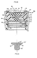
- Fig. 5 shows an alternative embodiment 50' of the elastomeric element.
- This embodiment is designed to respond rapidly to pressure changes and is particularly useful in applications, such as trajectory drinking fountains, in which a stabilized, rate-controlled stream must be quickly established.
- the element 50' is in all respects the same as the element 50 previously described except that it has a flange 54' having a smaller overall height and a small annular groove 68 formed in the lower surface 58' immediately adjacent the stem 52'.
- both the mass of the flange and its resistance to deflection are reduced resulting in a decrease in response time.
- the attachment includes a generally cylindrical, 2-part housing 84 consisting of an upper section 86 detachably coupled to a lower section 88.
- the housing sections 86 and 88 may be injection molded parts made of a material such as "Delrin".
- the housing 84 is enclosed within an outer metal shell 90 having an inwardly projecting lower lip 92 for supporting the housing 84, and an upper, externally threaded portion 94 for securing the attachment 80 to a faucet spout either directly or by means of an appropriate threaded adapter.
- a rubber washer 96 disposed on top of the housing insures a watertight seal between the attachment 80 and the faucet spout.
- a perforated plate 98 serving as a particle filter is retained by the upper housing section 86 just below washer 96. The plate 98 does not function as a flow conditioning means but only as a filter and may be omitted if desired.
- the upper housing section 86 includes a plate or partition 100 that divides the interior of housing section 86 into two chambers - an upper chamber 102 and a lower chamber 104. These chambers are connected by a plurality of flow passages 106 formed in the partition 100.
- the upper chamber 102 has a cylindrical side wall 108 that is faired smoothly into the partition 100 by means of a radiused corner 110.
- the lower chamber 104 has a cylindrical side wall 112 whose junction with the partition 100 is similarly radiused as indicated by the reference numeral 114.
- the cylindrical side walls 108 and 112 have the same diameter, although this need not be the case.
- the partition 100 also has a central opening 116 retaining an elastomeric flow control element 118 in all respects similar to the element 50 of Figs. 1-4.
- a central opening 116 retaining an elastomeric flow control element 118 in all respects similar to the element 50 of Figs. 1-4.
- the lower housing section 88 contains a flow conditioning means that, in the example shown in Fig. 6, is in the form of a laminar stream device that includes a pair of perforated plates 120 and a pair of screens 122, the plates and screens being arranged in a stack and separated by three identical ring spacers 124.
- the plate and screen stack is supported by a peripheral ledge 126 defined by an inwardly directed flange at the discharge end of the lower housing 88.
- the specific geometry of the plates and the screens and the spacings therebetween need not be discussed here.
- a complete description of a device for producing a laminar stream is contained in U.S. Patent No. 4,119,276, issued October 10, 1978, and entitled "Laminar Stream Spout Attachment".
- An advantage of the flow control device of the present invention is that the characteristics of the water flow discharged therefrom are compatible with the production of a laminar stream. It will be obvious to those skilled in the art, however, that other flow conditioning means, such as aerators, can be utilized in conjunction with the flow control device of the present invention in lieu of the laminar stream device that is specifically shown.
Landscapes
- Physics & Mathematics (AREA)
- General Physics & Mathematics (AREA)
- Engineering & Computer Science (AREA)
- Automation & Control Theory (AREA)
- Flow Control (AREA)
- Safety Valves (AREA)
Claims (5)
Priority Applications (1)
| Application Number | Priority Date | Filing Date | Title |
|---|---|---|---|
| AT81903040T ATE12554T1 (de) | 1980-11-03 | 1981-10-26 | Durchflusssteuervorrichtung mit elastomerem element. |
Applications Claiming Priority (2)
| Application Number | Priority Date | Filing Date | Title |
|---|---|---|---|
| US06/203,456 US4344459A (en) | 1980-11-03 | 1980-11-03 | Flow control device employing elastomeric element |
| US203456 | 1994-02-28 |
Publications (3)
| Publication Number | Publication Date |
|---|---|
| EP0063587A1 EP0063587A1 (de) | 1982-11-03 |
| EP0063587A4 EP0063587A4 (de) | 1983-03-04 |
| EP0063587B1 true EP0063587B1 (de) | 1985-04-03 |
Family
ID=22754091
Family Applications (1)
| Application Number | Title | Priority Date | Filing Date |
|---|---|---|---|
| EP81903040A Expired EP0063587B1 (de) | 1980-11-03 | 1981-10-26 | Durchflusssteuervorrichtung mit elastomerem element |
Country Status (3)
| Country | Link |
|---|---|
| US (1) | US4344459A (de) |
| EP (1) | EP0063587B1 (de) |
| WO (1) | WO1982001573A1 (de) |
Families Citing this family (37)
| Publication number | Priority date | Publication date | Assignee | Title |
|---|---|---|---|---|
| US4451359A (en) * | 1982-03-30 | 1984-05-29 | Daniel Osterberg | Hydraulic flow distributor in gold separator and method |
| US4807721A (en) * | 1986-03-21 | 1989-02-28 | Shoketsu Kinzoku Kabushiki Kaisha | Air line lubricator |
| US4894152A (en) * | 1987-08-13 | 1990-01-16 | Cerex Corporation | Fluid control device |
| US5425404A (en) * | 1993-04-20 | 1995-06-20 | Minnesota Mining And Manufacturing Company | Gravity feed fluid dispensing system |
| US5435451A (en) * | 1993-04-20 | 1995-07-25 | Minnesota Mining And Manufacturing Company | Bottle for containing a fluid |
| GB2286872B (en) * | 1994-02-22 | 1998-01-07 | Cistermiser Ltd | Variable flow restricting devices |
| US5738135A (en) * | 1994-12-19 | 1998-04-14 | Ecolab Inc. | Dispensing apparatus with line pressure diverter |
| US5655563A (en) * | 1994-12-19 | 1997-08-12 | Ecolab Inc. | Dispensing apparatus with line pressure diverter |
| DE19603393A1 (de) * | 1996-01-31 | 1997-08-07 | Wildfang Dieter Gmbh | Durchflußmengenregler oder dergleichen Drossel |
| US5799700A (en) * | 1996-06-27 | 1998-09-01 | Teh; Eutiquio L. | Automatic intravenous flow control device |
| DE19641233A1 (de) * | 1996-10-07 | 1998-04-09 | Mueller A & K Gmbh Co Kg | In eine Flüssigkeitsleitung oder die Aufnahmebohrung einer Armatur einsetzbarer Mengenregler |
| DE69817203T2 (de) | 1997-10-08 | 2004-06-17 | Minnesota Mining & Manufacturing Company, St. Paul | Ventil zur abgabe von flüssigkeit unter schwerkraft |
| US6145496A (en) * | 1998-04-07 | 2000-11-14 | Siemens Automotive Corporation | Fuel injector with porous element for atomizing fuel under air pressure |
| US6223791B1 (en) | 1999-10-21 | 2001-05-01 | 3M Innovative Properties Company | Gravity feed fluid dispensing valve |
| US6390122B1 (en) * | 2000-10-11 | 2002-05-21 | Hays Fluid Controls, A Division Of Romac Industries, Inc. | Fluid flow control valve and orifice therefor |
| US6450214B1 (en) | 2001-08-31 | 2002-09-17 | 3M Innovative Properties Company | Gravity feed fluid dispensing valve |
| US6595235B1 (en) | 2003-01-31 | 2003-07-22 | Hays Fluid Controls, A Divison Of Romac Industries, Inc. | Two-way orifice seat |
| FR2871389B1 (fr) * | 2004-06-11 | 2006-09-22 | St Mihiel Sas Soc Par Actions | Lance d'incendie a debit de fluide constant |
| US7222643B2 (en) * | 2004-10-21 | 2007-05-29 | Vernay Laboratories, Inc. | Internal post flow control |
| HU230292B1 (hu) * | 2006-03-13 | 2015-12-28 | BERY INTELLECTUAL PROPERTIES Szellemi Tulajdonjogokat Hasznosító és Kezelő Kf | Szabályozószelep alakos tömítőelemmel |
| US10017924B2 (en) | 2006-12-06 | 2018-07-10 | Neoperl Gmbh | Sanitary installation element |
| US9481986B2 (en) | 2006-12-06 | 2016-11-01 | Neoperl Gmbh | Sanitary installation element |
| US7775242B2 (en) * | 2007-09-05 | 2010-08-17 | Ceramphysics, Inc. | Solid state regulator for natural gas |
| US8986253B2 (en) | 2008-01-25 | 2015-03-24 | Tandem Diabetes Care, Inc. | Two chamber pumps and related methods |
| US8408421B2 (en) | 2008-09-16 | 2013-04-02 | Tandem Diabetes Care, Inc. | Flow regulating stopcocks and related methods |
| WO2010033878A2 (en) | 2008-09-19 | 2010-03-25 | David Brown | Solute concentration measurement device and related methods |
| US20110152770A1 (en) | 2009-07-30 | 2011-06-23 | Tandem Diabetes Care, Inc. | Infusion pump system with disposable cartridge having pressure venting and pressure feedback |
| ITTO20110615A1 (it) * | 2011-07-13 | 2013-01-14 | Elbi Int Spa | Regolatore idraulico di portata |
| US9180242B2 (en) | 2012-05-17 | 2015-11-10 | Tandem Diabetes Care, Inc. | Methods and devices for multiple fluid transfer |
| TWI468607B (zh) * | 2012-07-12 | 2015-01-11 | Delta Electronics Inc | 穩流裝置 |
| US20140097374A1 (en) * | 2012-10-09 | 2014-04-10 | Brasscraft Manufacturing Company | Excess flow valve with flexible diaphragm member |
| US9173998B2 (en) | 2013-03-14 | 2015-11-03 | Tandem Diabetes Care, Inc. | System and method for detecting occlusions in an infusion pump |
| TWI687611B (zh) | 2014-04-17 | 2020-03-11 | 美商威士塔戴爾泰克有限責任公司 | 用於密封地結合相對流體導管端口之環形襯墊及形成一高純度流體接頭之方法 |
| US9777857B2 (en) * | 2016-01-08 | 2017-10-03 | Pao-Tang Chen | Flow control valve |
| US10022734B2 (en) | 2016-11-14 | 2018-07-17 | Chronomite Laboratories, Inc. | Variable dual flow fitting |
| DE202018102383U1 (de) * | 2018-04-27 | 2019-07-30 | Neoperl Gmbh | Durchflussmengenregler |
| JP7464998B2 (ja) * | 2018-06-01 | 2024-04-10 | セーフビーブイエム コーポレイション | バッグバルブマスクのための圧力安全デバイス |
Family Cites Families (9)
| Publication number | Priority date | Publication date | Assignee | Title |
|---|---|---|---|---|
| US2777464A (en) * | 1951-03-07 | 1957-01-15 | Detroit Controls Corp | Flow control devices |
| GB783323A (en) * | 1954-09-08 | 1957-09-18 | Robertshaw Fulton Controls Co | Constant flow control valve |
| US2851060A (en) * | 1955-02-23 | 1958-09-09 | Fleischer Henry | Fluid flow control fitting |
| US2878836A (en) * | 1957-05-13 | 1959-03-24 | Scovill Manufacturing Co | Two-piece flow control valve |
| US2948296A (en) * | 1958-03-24 | 1960-08-09 | Powers Regulator Co | Variable constant flow device |
| US3326242A (en) * | 1964-05-20 | 1967-06-20 | American Radiator & Standard | Fluid flow control device |
| US3409050A (en) * | 1965-10-12 | 1968-11-05 | Harry Swartz | Flow restrictor |
| US3592237A (en) * | 1969-06-23 | 1971-07-13 | Alwin Borschers | Throttle means for maintaining constant flow |
| US3630455A (en) * | 1970-03-31 | 1971-12-28 | American Standard Inc | Spout end apparatus |
-
1980
- 1980-11-03 US US06/203,456 patent/US4344459A/en not_active Expired - Lifetime
-
1981
- 1981-10-26 WO PCT/US1981/001451 patent/WO1982001573A1/en not_active Ceased
- 1981-10-26 EP EP81903040A patent/EP0063587B1/de not_active Expired
Also Published As
| Publication number | Publication date |
|---|---|
| US4344459A (en) | 1982-08-17 |
| EP0063587A1 (de) | 1982-11-03 |
| EP0063587A4 (de) | 1983-03-04 |
| WO1982001573A1 (en) | 1982-05-13 |
Similar Documents
| Publication | Publication Date | Title |
|---|---|---|
| EP0063587B1 (de) | Durchflusssteuervorrichtung mit elastomerem element | |
| US4000857A (en) | Flow control aerator | |
| US4428397A (en) | Fluid flow control device | |
| US3995664A (en) | Flow control device | |
| US5803368A (en) | Aerator for water taps | |
| EP0024670B1 (de) | Selbstregelnde Düse für eine Zuführleitung mit konstantem Durchfluss | |
| US5082240A (en) | Quiet water valve | |
| US5226446A (en) | Flow noise reduction | |
| JP4690293B2 (ja) | 流体制御バルブ | |
| US4161291A (en) | Emitter | |
| US4054152A (en) | Check valve | |
| US10013000B2 (en) | Sanitary insertion unit | |
| JPH05276842A (ja) | 調整滴下潅漑放出器 | |
| US5071071A (en) | Aerator structure for a water faucet | |
| JPS6331621B2 (de) | ||
| US3023767A (en) | Vacuum breaker | |
| US2936790A (en) | Noise reducing flow control device | |
| US2989086A (en) | Solid flow control valve | |
| US3630455A (en) | Spout end apparatus | |
| CA1224446A (en) | Liquid flow rate controller | |
| EP0059697B1 (de) | Vorrichtung für Schieber, insbesondere für Mischventile | |
| US4512548A (en) | Valve with a device for the attenuation of acoustic vibrations self-excited by the working medium | |
| US3006378A (en) | Resilient plural orifice flow control | |
| US20240151315A1 (en) | Pressure Valve for a Liquid | |
| EP0036405A1 (de) | Durchflussreglungsvorrichtung |
Legal Events
| Date | Code | Title | Description |
|---|---|---|---|
| PUAI | Public reference made under article 153(3) epc to a published international application that has entered the european phase |
Free format text: ORIGINAL CODE: 0009012 |
|
| AK | Designated contracting states |
Designated state(s): AT CH DE FR GB LI LU NL SE |
|
| 17P | Request for examination filed |
Effective date: 19821126 |
|
| RHK1 | Main classification (correction) |
Ipc: G05D 7/01 |
|
| GRAA | (expected) grant |
Free format text: ORIGINAL CODE: 0009210 |
|
| AK | Designated contracting states |
Designated state(s): AT CH DE FR GB LI LU NL SE |
|
| REF | Corresponds to: |
Ref document number: 12554 Country of ref document: AT Date of ref document: 19850415 Kind code of ref document: T |
|
| REF | Corresponds to: |
Ref document number: 3169724 Country of ref document: DE Date of ref document: 19850509 |
|
| ET | Fr: translation filed | ||
| PG25 | Lapsed in a contracting state [announced via postgrant information from national office to epo] |
Ref country code: LU Free format text: LAPSE BECAUSE OF NON-PAYMENT OF DUE FEES Effective date: 19851031 |
|
| REG | Reference to a national code |
Ref country code: CH Ref legal event code: PUE Owner name: OMNI PRODUITS SA |
|
| PLBE | No opposition filed within time limit |
Free format text: ORIGINAL CODE: 0009261 |
|
| STAA | Information on the status of an ep patent application or granted ep patent |
Free format text: STATUS: NO OPPOSITION FILED WITHIN TIME LIMIT |
|
| REG | Reference to a national code |
Ref country code: GB Ref legal event code: 732 |
|
| REG | Reference to a national code |
Ref country code: FR Ref legal event code: TP |
|
| 26N | No opposition filed | ||
| NLS | Nl: assignments of ep-patents |
Owner name: OMNI PRODUITS SA TE GENEVE, ZWITSERLAND. |
|
| PGFP | Annual fee paid to national office [announced via postgrant information from national office to epo] |
Ref country code: AT Payment date: 19861015 Year of fee payment: 6 |
|
| PGFP | Annual fee paid to national office [announced via postgrant information from national office to epo] |
Ref country code: NL Payment date: 19871031 Year of fee payment: 7 |
|
| PG25 | Lapsed in a contracting state [announced via postgrant information from national office to epo] |
Ref country code: GB Effective date: 19891026 Ref country code: AT Effective date: 19891026 |
|
| PG25 | Lapsed in a contracting state [announced via postgrant information from national office to epo] |
Ref country code: SE Effective date: 19891027 |
|
| PG25 | Lapsed in a contracting state [announced via postgrant information from national office to epo] |
Ref country code: LI Effective date: 19891031 Ref country code: CH Effective date: 19891031 |
|
| PG25 | Lapsed in a contracting state [announced via postgrant information from national office to epo] |
Ref country code: NL Effective date: 19900501 |
|
| NLV4 | Nl: lapsed or anulled due to non-payment of the annual fee | ||
| GBPC | Gb: european patent ceased through non-payment of renewal fee | ||
| PG25 | Lapsed in a contracting state [announced via postgrant information from national office to epo] |
Ref country code: FR Effective date: 19900629 |
|
| REG | Reference to a national code |
Ref country code: CH Ref legal event code: PL |
|
| PG25 | Lapsed in a contracting state [announced via postgrant information from national office to epo] |
Ref country code: DE Effective date: 19900703 |
|
| REG | Reference to a national code |
Ref country code: FR Ref legal event code: ST |
|
| REG | Reference to a national code |
Ref country code: LU Ref legal event code: TP Owner name: OMNI PRODUITS S.A. GENEVE Effective date: 19860127 |
|
| EUG | Se: european patent has lapsed |
Ref document number: 81903040.4 Effective date: 19900705 |