EP0063355A2 - Timing device for time switch - Google Patents
Timing device for time switch Download PDFInfo
- Publication number
- EP0063355A2 EP0063355A2 EP82103131A EP82103131A EP0063355A2 EP 0063355 A2 EP0063355 A2 EP 0063355A2 EP 82103131 A EP82103131 A EP 82103131A EP 82103131 A EP82103131 A EP 82103131A EP 0063355 A2 EP0063355 A2 EP 0063355A2
- Authority
- EP
- European Patent Office
- Prior art keywords
- presetting
- timing device
- scale plate
- time switch
- metallic
- Prior art date
- Legal status (The legal status is an assumption and is not a legal conclusion. Google has not performed a legal analysis and makes no representation as to the accuracy of the status listed.)
- Granted
Links
Images


Classifications
-
- H—ELECTRICITY
- H01—ELECTRIC ELEMENTS
- H01H—ELECTRIC SWITCHES; RELAYS; SELECTORS; EMERGENCY PROTECTIVE DEVICES
- H01H43/00—Time or time-programme switches providing a choice of time-intervals for executing one or more switching actions and automatically terminating their operations after the programme is completed
- H01H43/02—Details
- H01H43/04—Means for time setting
- H01H43/06—Means for time setting comprising separately adjustable parts for each programme step, e.g. with tappets
-
- G—PHYSICS
- G04—HOROLOGY
- G04C—ELECTROMECHANICAL CLOCKS OR WATCHES
- G04C23/00—Clocks with attached or built-in means operating any device at preselected times or after preselected time-intervals
- G04C23/02—Constructional details
- G04C23/08—Programming means
-
- Y—GENERAL TAGGING OF NEW TECHNOLOGICAL DEVELOPMENTS; GENERAL TAGGING OF CROSS-SECTIONAL TECHNOLOGIES SPANNING OVER SEVERAL SECTIONS OF THE IPC; TECHNICAL SUBJECTS COVERED BY FORMER USPC CROSS-REFERENCE ART COLLECTIONS [XRACs] AND DIGESTS
- Y10—TECHNICAL SUBJECTS COVERED BY FORMER USPC
- Y10T—TECHNICAL SUBJECTS COVERED BY FORMER US CLASSIFICATION
- Y10T74/00—Machine element or mechanism
- Y10T74/21—Elements
- Y10T74/2101—Cams
- Y10T74/2102—Adjustable
- Y10T74/2106—Timer devices
Definitions
- the present invention relates to a timing device for time switch.
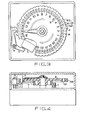
- Such type of a conventional timing device comprises a switch 1, an operating lever 2 for the switch 1, and time scale 3 disposed.on the front surface of the timing device as shown in Figs. 1 - 5.
- the timing device further comprises a scale plate 6 possessing plug-in portions 5 each consisting of a slot 51, a groove 52 and a frame 53 and for fitting a presetting element 4 thereinto, and such plug-in portions being arranged on the circumferential part of the scale plate so as to correspond to the respective time scales, presetting elements 4 each having n-shape being capable of inserting the same to fit into the aforesaid plug-in portion 5, a clock mechanism 7 and the like parts.
- the switch 1 can be kept ON for only a period of time of 30 minutes from the time corresponding to the inserted position of the presetting element.
- the switch 1 can be kept ON for a period of time of n x 30 minutes from the time corresponding to the initial fitted position of a presetting element 4.
- both the scale plate 6 and presetting elements 4 shown in Figs. 1 and 2 are made of a metal material, respectively, whilst both the scale plate 6 and presetting elements 4 shown in Figs. 3 and 4 are made of a plastic material, respectively.
- the former time switch (Figs. 1 and 2), even if a thickness of the presetting element 4 is thinned, a sufficient elastic force of the scale plate 6 as well as a strength required for the operation of the lever 2 can be obtained. Accordingly, the former time switch 1 has an advantage in that the minimum presetting interval can be fixed at a small value. On the other hand, however, since the plug-in portions 5 must be worked by means of press-cutting in this type of the time switch, a thickness T of the scale plate comes to be substantially equal to a width A of each slot 51 and groove 52.
- the former time switch has a disadvantage in that an inserted presetting element 4 .easily topples in the rotational direction of the scale plate 6 at the resiliently engaged portion as its fulcrum, so that it is difficult to keep the position of the element so inserted in the prescribed position.
- a thickness of a presetting element 4 With decrease of a thickness of a presetting element 4, a thickness of a cutting blade in a press tool for cutting plug-in portions 5 of the scale plate 6 becomes also thin. Besides a number of such thin cutting blades are required for the fabrication of the former time switch 1, and as a result the greatest possible care is necessary for the press operation.
- there is also such a disadvantage that considerable costs and man-power are required for maintaining manufacture properties of such press tool in respect of the former time switch 1.
- the latter time switch (Figs. 3 and 4) has advantages in that it is excellent in the mass productivity and can be inexpensively manufactured, besides it becomes easy to thicken a thickness of the scale plate 6, so that toppling of a presetting element 4 can be prevented to easily keep the position of the presetting element inserted in the prescribed position.
- a thickness of the presetting element 4 in order to obtain a sufficient elastic force for the scale plate 6 and a strength required for operating the lever 2, a thickness of the presetting element 4 must be thickened, so that the minimum presetting interval increases.
- an external dimension of the scale plate 6 must be increased.
- the latter time switch has a disadvantage in that a dimension of the opening of a rT-shaped presetting element 4 expands and deforms by means of stress relaxation phenomenon of plastic material due to change in ambient temperature and the like phenomena thereby to lose the elastic force upon the scale plate 6, and as a consequence the presetting element 4 inserted falls off from the plug-in portion 5.
- Figs. 6 and 7 show a timing device according to one embodiment of the present invention in which a scale plate 6 is a plastics part similarly to a conventional one shown in Figs. 3 and 4.
- the-scale plate 6 of this invention differs from the conventional one in that a doughnut-like metallic disc 8 is in molded-in insert state with respect to the scale plate.
- the scale plate 6 is arranged in such that the inner circumference of the metallic disc 8 is exposed in slots 51, while the outer circumference of the metallic disc 8 is exposed in grooves 52, and a metallic presetting element 4 is resiliently engaged with the exposed portion thus formed.
- FIGs. 8 - 11 are sectional views each showing another embodiment of the timing device according to this invention.
- Fig. 8 shows a metallic disc 8 having a modified profile with n-shape in the vertical section thereof.
- F ig. 9 illustrates a metallic disc 8 having a modified elliptical profile in the vertical section.
- Fig. 10 shows a metallic disc 8 having a modified complete circular profile in the vertical section.
- Fig. 11 shows an example in which two metallic discs 8a and 8b are used.
- Figs. 12 and 13 illustrate still another embodiment of the timing device of the invention in which a scale plate 6 is composed of a metallic disc portion 8 and a plastic guide portion 9 integrally attached to the metallic disc 8 by means of outsert molding method upon the outer peripheral portion of the disc.
- the metallic disc portion 8 has such a figure that a part of frames 53 (Fig. 1) of the conventional scale plate 6, for example, a part of ninety six frames 53 is omitted to leave only twelve frames 81 so as to keep regular intervals (30° each) and all the grooves 52 are cancelled.
- the metallic disc portion 8 is formed into a double ring shape having the outer and inner rings. Small holes 82 are formed on the metallic disc portion 8 to further increase binding power between the metallic disc portion and the guide portion 9.
- the guide portion 9 possesses slots 91 and grooves 92 corresponding to the slots 51 and the grooves 52, respectively, in the conventional scale plate 6.
- the guide portion 9 has such a depth for the presetting element 4 in the inserting direction which is sufficient for preventing toppling of the presetting element 4 in the circumferential direction of the scale plate.
- time scale 3 is provided on the surface of-the scale plate 6 .
- the outermost periphery 83 of the aforesaid metallic disc portion 8 is exposed in the grooves 92, and the second outer periphery 84 is exposed in the slots 91 as shown in Figs. 12 and 13.
- the guide portion 9 is integrally molded together with the metallic disc portion 8 in accordance with outsert molding method in such manner that the frames 81 of the metallic disc portion 8 correspond to a frame 93 of the guide portion 9.
- the scale plate 6 is arranged in such that the slots 51 and the grooves 52 thereof serve to position the presetting elements as well as to keep the position of an element inserted in the prescribed position, and a resiliently engaging portion of the presetting element 4 is composed of the metallic disc, so that the presetting element 4 may be fabricated from a thin metal plate.
- the timing device in accordance with the present invention has the following advantages as compared with a conventional timing device in which a plastic presetting element 4 is employed.
- the presetting element has several times larger strength than that of a conventional one, so that the presetting element of this invention can easily operate even a switch 1 having a large switching capacity and being required for a large power for the operation thereof.
- the presetting element 4 having a large elastic force can easily be obtained.
- the outer dimension of the presetting element 4 is made to be identical to that of the scale plate 6, the minimum preset interval can be reduced, while when the minimum preset interval of the timing device of this invention is identical to that of a conventional timing device, the compact scale plate 6 can be obtained in the present invention.
- the metallic disc 8 of the present invention has a simple doughnut shape and has not the slots 51 and grooves 52 as in the conventional metallic scale plate 6, and therefore the present invention has the advantages as described hereinbelow.
- the shape of a press tool may be simple, the costs therefor becomes inexpensive, besides a life of the mold tool can remarkably be prolonged.
- a density of the plug-in portions 5 to be provided on the scale plate 6 can be increased and consequently, a timing device with a small minimum preset interval can further compactly be fabricated.
- the timing device is arranged in such that the guide portion 9 being outsert-molded serves to position the locations of the presetting elements 4 to be inserted as well as to keep the position of an element inserted in the prescribed position, and the metallic disc portion 8 serves to resiliently engage with the presetting element 4 in order to prevent falling the element off.
- the timing device of the present invention has further the following advantages.
- the metallic disc portion 8 does not require a number of slots 51 and grooves 52 unlike the scale plate 6 in a conventional timing device, so that a construction of the press tool therefor becomes simple, whereby a solid, inexpensive and durable press tool may be utilized in the invention.
Landscapes
- Physics & Mathematics (AREA)
- General Physics & Mathematics (AREA)
- Rotary Switch, Piano Key Switch, And Lever Switch (AREA)
- Push-Button Switches (AREA)
Abstract
Description
- The present invention relates to a timing device for time switch.
- Such type of a conventional timing device comprises a
switch 1, anoperating lever 2 for theswitch 1, andtime scale 3 disposed.on the front surface of the timing device as shown in Figs. 1 - 5. The timing device further comprises ascale plate 6 possessing plug-in portions 5 each consisting of aslot 51, agroove 52 and aframe 53 and for fitting a presettingelement 4 thereinto, and such plug-in portions being arranged on the circumferential part of the scale plate so as to correspond to the respective time scales, presettingelements 4 each having n-shape being capable of inserting the same to fit into the aforesaid plug-in portion 5, aclock mechanism 7 and the like parts. - In this arrangement, if a
presetting element 4 has previously been fitted into the plug-in portion 5 at the position corresponding to a desired time scale on thescale plate 6,such scale plate 6 is rotated by means of the clock mechanism and when the prescribed time passed away, thelever 2 is shifted from a state illustrated by means of broken line to a state shown by solid line, in other words, thelever 2 is shifted in counterclockwise direction by means of the presettingelement 4 inserted to turn theswitch 1 ON. Further, when time elapsed and the presettingelement 4 passed through thelever 2, the same is returned to the state illustrated by broken line to turn the switch OFF. - Referring to Figs. 1 and 2 showing an example of a time switch in which the minimum presetting interval is fixed at 15 minutes, so that
scale plate 6. Namely, this means that when one presettingelement 4 is inserted in a plug-in portion, theswitch 1 may be kept ON for only a period of time of 15 minutes from the time corresponding to the inserted position. Furthermore, whenn presetting elements 4 are inserted in n plug-in portions in succession, theswitch 1 can be kept ON state for a period of time ofn x 15 minutes from the time corresponding to the initial inserted position of apresetting element 4. - Referring now to Figs. 3 and 4 which show an example of a time switch in which the minimum presetting interval is fixed at 30 minutes, so that

scale plate 6. Thus, when one presettingelement 4 is inserted in a plug-in portion, theswitch 1 can be kept ON for only a period of time of 30 minutes from the time corresponding to the inserted position of the presetting element. In the case whenn presetting elements 4 are fitted in n plug-in portions in succession, theswitch 1 can be kept ON for a period of time of n x 30 minutes from the time corresponding to the initial fitted position of apresetting element 4. - In the above stated conventional time switches, both the
scale plate 6 andpresetting elements 4 shown in Figs. 1 and 2 are made of a metal material, respectively, whilst both thescale plate 6 and presettingelements 4 shown in Figs. 3 and 4 are made of a plastic material, respectively. - In the former time switch (Figs. 1 and 2), even if a thickness of the
presetting element 4 is thinned, a sufficient elastic force of thescale plate 6 as well as a strength required for the operation of thelever 2 can be obtained. Accordingly, theformer time switch 1 has an advantage in that the minimum presetting interval can be fixed at a small value. On the other hand, however, since the plug-in portions 5 must be worked by means of press-cutting in this type of the time switch, a thickness T of the scale plate comes to be substantially equal to a width A of eachslot 51 andgroove 52. For this reason, the former time switch has a disadvantage in that an inserted presettingelement 4 .easily topples in the rotational direction of thescale plate 6 at the resiliently engaged portion as its fulcrum, so that it is difficult to keep the position of the element so inserted in the prescribed position. In addition, with decrease of a thickness of apresetting element 4, a thickness of a cutting blade in a press tool for cutting plug-in portions 5 of thescale plate 6 becomes also thin. Besides a number of such thin cutting blades are required for the fabrication of theformer time switch 1, and as a result the greatest possible care is necessary for the press operation. Moreover, there is also such a disadvantage that considerable costs and man-power are required for maintaining manufacture properties of such press tool in respect of theformer time switch 1. - As compared with the former time switch, the latter time switch (Figs. 3 and 4) has advantages in that it is excellent in the mass productivity and can be inexpensively manufactured, besides it becomes easy to thicken a thickness of the
scale plate 6, so that toppling of apresetting element 4 can be prevented to easily keep the position of the presetting element inserted in the prescribed position. However, in order to obtain a sufficient elastic force for thescale plate 6 and a strength required for operating thelever 2, a thickness of thepresetting element 4 must be thickened, so that the minimum presetting interval increases. Thus, there is such a disadvantage that if the minimum presetting interval is identical to that of the former time switch, an external dimension of thescale plate 6 must be increased. In addition, the latter time switch has a disadvantage in that a dimension of the opening of a rT-shaped presetting element 4 expands and deforms by means of stress relaxation phenomenon of plastic material due to change in ambient temperature and the like phenomena thereby to lose the elastic force upon thescale plate 6, and as a consequence the presettingelement 4 inserted falls off from the plug-in portion 5. - It is an object of the present invention to provide a timing device for time switch by which the above described disadvantages of conventional time switches can be eliminated, and the timing device for time switch according to the present invention can easily and inexpensively be manufactured, besides such compact timing device for time switch with a small minimum presetting interval can be fabricated without increasing a shape of the scale plate in accordance with the present invention.
-
- Fig. 1 is a front view showing a conventional timing device;
- Fig. 2 is a side view showing the timing device of Fig. 1;
- Fig. 3 is a front view showing another conventional timing device;
- Fig. 4 is a side view showing the timing device of Fig. 3;
- Fig. 5 is an explanatory view showing an insertion state of a conventional presetting element;
- Fig. 6 is a front view showing a timing device for time switch in accordance with an embodiment of the present invention;
- Fig. 7 is a side view showing the timing device of Fig. 6;
- Figs 8 - 11 are sectional views each showing an essential part of another embodiment of the present invention;
- Fig. 12 is a front view showing a timing device in accordance with still another embodiment of the present invention; and
- Fig. 13 is a side view showing the timing device of Fig. 12.
- Figs. 6 and 7 show a timing device according to one embodiment of the present invention in which a
scale plate 6 is a plastics part similarly to a conventional one shown in Figs. 3 and 4. However, the-scale plate 6 of this invention differs from the conventional one in that a doughnut-likemetallic disc 8 is in molded-in insert state with respect to the scale plate. Namely, thescale plate 6 is arranged in such that the inner circumference of themetallic disc 8 is exposed inslots 51, while the outer circumference of themetallic disc 8 is exposed ingrooves 52, and ametallic presetting element 4 is resiliently engaged with the exposed portion thus formed. - Furthermore Figs. 8 - 11 are sectional views each showing another embodiment of the timing device according to this invention.
- More specifically, Fig. 8 shows a metallic disc 8 having a modified profile with n-shape in the vertical section thereof.
- Fig. 9 illustrates a
metallic disc 8 having a modified elliptical profile in the vertical section. - Further Fig. 10 shows a
metallic disc 8 having a modified complete circular profile in the vertical section. - In addition, Fig. 11 shows an example in which two metallic discs 8a and 8b are used.
- Next, Figs. 12 and 13 illustrate still another embodiment of the timing device of the invention in which a
scale plate 6 is composed of ametallic disc portion 8 and aplastic guide portion 9 integrally attached to themetallic disc 8 by means of outsert molding method upon the outer peripheral portion of the disc. - In the present embodiment, the
metallic disc portion 8 has such a figure that a part of frames 53 (Fig. 1) of theconventional scale plate 6, for example, a part of ninety sixframes 53 is omitted to leave only twelveframes 81 so as to keep regular intervals (30° each) and all thegrooves 52 are cancelled. Namely, themetallic disc portion 8 is formed into a double ring shape having the outer and inner rings.Small holes 82 are formed on themetallic disc portion 8 to further increase binding power between the metallic disc portion and theguide portion 9. Theguide portion 9 possessesslots 91 andgrooves 92 corresponding to theslots 51 and thegrooves 52, respectively, in theconventional scale plate 6. Further theguide portion 9 has such a depth for the presettingelement 4 in the inserting direction which is sufficient for preventing toppling of the presettingelement 4 in the circumferential direction of the scale plate. In addition,time scale 3 is provided on the surface of-the scale plate 6. Moreover theoutermost periphery 83 of the aforesaidmetallic disc portion 8 is exposed in thegrooves 92, and the secondouter periphery 84 is exposed in theslots 91 as shown in Figs. 12 and 13. Besides theguide portion 9 is integrally molded together with themetallic disc portion 8 in accordance with outsert molding method in such manner that theframes 81 of themetallic disc portion 8 correspond to aframe 93 of theguide portion 9. - As described above, according to the present invention, the
scale plate 6 is arranged in such that theslots 51 and thegrooves 52 thereof serve to position the presetting elements as well as to keep the position of an element inserted in the prescribed position, and a resiliently engaging portion of the presettingelement 4 is composed of the metallic disc, so that thepresetting element 4 may be fabricated from a thin metal plate. Thus, the timing device in accordance with the present invention has the following advantages as compared with a conventional timing device in which aplastic presetting element 4 is employed. - There is not such a case where the presetting
element 4 is deformed by means of the influence of ambient temperature. - The presetting element has several times larger strength than that of a conventional one, so that the presetting element of this invention can easily operate even a
switch 1 having a large switching capacity and being required for a large power for the operation thereof. - The presetting
element 4 having a large elastic force can easily be obtained. - If the outer dimension of the
presetting element 4 is made to be identical to that of thescale plate 6, the minimum preset interval can be reduced, while when the minimum preset interval of the timing device of this invention is identical to that of a conventional timing device, thecompact scale plate 6 can be obtained in the present invention. - Besides the
metallic disc 8 of the present invention has a simple doughnut shape and has not theslots 51 andgrooves 52 as in the conventionalmetallic scale plate 6, and therefore the present invention has the advantages as described hereinbelow. - Since the shape of a press tool may be simple, the costs therefor becomes inexpensive, besides a life of the mold tool can remarkably be prolonged.
- Since the shape of a product is simple, cycles for the press-cutting operation can be elevated, so that the improvement of mass productivity can be attained.
- A density of the plug-in portions 5 to be provided on the
scale plate 6 can be increased and consequently, a timing device with a small minimum preset interval can further compactly be fabricated. - Moreover, in accordance with the present invention, the timing device is arranged in such that the
guide portion 9 being outsert-molded serves to position the locations of thepresetting elements 4 to be inserted as well as to keep the position of an element inserted in the prescribed position, and themetallic disc portion 8 serves to resiliently engage with thepresetting element 4 in order to prevent falling the element off. As a result, the timing device of the present invention has further the following advantages. - Unlike a conventional timing device, there is not such trouble that an operating time scatters due to toppling of a
presetting element 4 mounted on the timing device in the circumferential direction of thescale plate 6 in the present invention. - The
metallic disc portion 8 according to the present invention does not require a number ofslots 51 andgrooves 52 unlike thescale plate 6 in a conventional timing device, so that a construction of the press tool therefor becomes simple, whereby a solid, inexpensive and durable press tool may be utilized in the invention. - In the above embodiments, such a
metallic disc 8 having a profile fabricated from a metallic plate by means of press-cutting was employed. In this respect, however, it is to be noted that manners such as press bending, press drawing, die casting, forging and the like may be utilized for fabricating themetallic disc 8 in the present invention.
Claims (5)
Applications Claiming Priority (4)
| Application Number | Priority Date | Filing Date | Title |
|---|---|---|---|
| JP57393/81 | 1981-04-15 | ||
| JP5739481A JPS57172625A (en) | 1981-04-15 | 1981-04-15 | Time switch time limit setting device |
| JP5739381A JPS57172624A (en) | 1981-04-15 | 1981-04-15 | Time switch time limit setting device |
| JP57394/81 | 1981-04-15 |
Publications (4)
| Publication Number | Publication Date |
|---|---|
| EP0063355A2 true EP0063355A2 (en) | 1982-10-27 |
| EP0063355A3 EP0063355A3 (en) | 1983-05-25 |
| EP0063355B1 EP0063355B1 (en) | 1986-01-02 |
| EP0063355B2 EP0063355B2 (en) | 1989-02-08 |
Family
ID=26398433
Family Applications (1)
| Application Number | Title | Priority Date | Filing Date |
|---|---|---|---|
| EP82103131A Expired EP0063355B2 (en) | 1981-04-15 | 1982-04-14 | Timing device for time switch |
Country Status (3)
| Country | Link |
|---|---|
| US (1) | US4436969A (en) |
| EP (1) | EP0063355B2 (en) |
| DE (1) | DE3268233D1 (en) |
Cited By (2)
| Publication number | Priority date | Publication date | Assignee | Title |
|---|---|---|---|---|
| FR2537337A1 (en) * | 1982-11-10 | 1984-06-08 | Matsushita Electric Works Ltd | |
| DE19948707A1 (en) * | 1999-10-09 | 2001-05-17 | Schwenk Kg Theben Werk | Electrical switching mechanism for time switches |
Families Citing this family (5)
| Publication number | Priority date | Publication date | Assignee | Title |
|---|---|---|---|---|
| DE8602885U1 (en) * | 1986-02-05 | 1986-03-27 | Dieter Gräßlin Feinwerktechnik, 7742 St Georgen | Electrical device switch with a device for setting and / or compensating the forward travel of the actuator |
| US4796484A (en) * | 1987-03-17 | 1989-01-10 | Emhart Industries, Inc. | Shaft detent assembly for a timing mechanism |
| DE3825308A1 (en) * | 1988-07-26 | 1990-02-01 | Weg Legrand Gmbh | Electrical or electronic switching apparatus or control apparatus of slimline construction, especially a time switch |
| JP3134986B2 (en) * | 1996-11-27 | 2001-02-13 | 船井電機株式会社 | Component locking device for chassis |
| US7777600B2 (en) * | 2004-05-20 | 2010-08-17 | Powerpath Technologies Llc | Eddy current inductive drive electromechanical liner actuator and switching arrangement |
Citations (6)
| Publication number | Priority date | Publication date | Assignee | Title |
|---|---|---|---|---|
| FR1212995A (en) * | 1958-10-21 | 1960-03-28 | Telemecanique Electrique | Improvements to combinator drums intended for controlling electrical contacts |
| US3637958A (en) * | 1971-03-01 | 1972-01-25 | Collins Radio Co | Cam-operated electric timing mechanism with improved adjustable pin coding and retaining structure |
| US3872823A (en) * | 1972-03-02 | 1975-03-25 | Amf Inc | Time switches |
| DE2935893A1 (en) * | 1978-09-14 | 1980-03-27 | Mitsubishi Electric Corp | TIMER |
| DE2845272A1 (en) * | 1978-10-18 | 1980-04-24 | Graesslin Feinwerktech | Timing disc for timer clock - has adjustable switch riders prevented from being removed by integral locking teeth |
| DE2902826A1 (en) * | 1979-01-23 | 1980-07-31 | Licentia Gmbh | Electrical contact drum controller - has cams held by catches in grooves of extruded drum operating contact levers |
-
1982
- 1982-04-14 EP EP82103131A patent/EP0063355B2/en not_active Expired
- 1982-04-14 DE DE8282103131T patent/DE3268233D1/en not_active Expired
- 1982-04-14 US US06/368,127 patent/US4436969A/en not_active Expired - Fee Related
Patent Citations (6)
| Publication number | Priority date | Publication date | Assignee | Title |
|---|---|---|---|---|
| FR1212995A (en) * | 1958-10-21 | 1960-03-28 | Telemecanique Electrique | Improvements to combinator drums intended for controlling electrical contacts |
| US3637958A (en) * | 1971-03-01 | 1972-01-25 | Collins Radio Co | Cam-operated electric timing mechanism with improved adjustable pin coding and retaining structure |
| US3872823A (en) * | 1972-03-02 | 1975-03-25 | Amf Inc | Time switches |
| DE2935893A1 (en) * | 1978-09-14 | 1980-03-27 | Mitsubishi Electric Corp | TIMER |
| DE2845272A1 (en) * | 1978-10-18 | 1980-04-24 | Graesslin Feinwerktech | Timing disc for timer clock - has adjustable switch riders prevented from being removed by integral locking teeth |
| DE2902826A1 (en) * | 1979-01-23 | 1980-07-31 | Licentia Gmbh | Electrical contact drum controller - has cams held by catches in grooves of extruded drum operating contact levers |
Cited By (3)
| Publication number | Priority date | Publication date | Assignee | Title |
|---|---|---|---|---|
| FR2537337A1 (en) * | 1982-11-10 | 1984-06-08 | Matsushita Electric Works Ltd | |
| DE19948707A1 (en) * | 1999-10-09 | 2001-05-17 | Schwenk Kg Theben Werk | Electrical switching mechanism for time switches |
| DE19948707C2 (en) * | 1999-10-09 | 2002-06-20 | Schwenk Kg Theben Werk | Electrical switching mechanism for time switches |
Also Published As
| Publication number | Publication date |
|---|---|
| EP0063355A3 (en) | 1983-05-25 |
| US4436969A (en) | 1984-03-13 |
| DE3268233D1 (en) | 1986-02-13 |
| EP0063355B2 (en) | 1989-02-08 |
| EP0063355B1 (en) | 1986-01-02 |
Similar Documents
| Publication | Publication Date | Title |
|---|---|---|
| US4789370A (en) | Apparatus for interlocking structural elements of toy disks | |
| US4462697A (en) | Integral plastic strap and bezel for a wristwatch | |
| EP0063355A2 (en) | Timing device for time switch | |
| EP0074227A1 (en) | Adapter permitting smaller size battery cell to function in larger size applications | |
| KR20050044610A (en) | Method of producing one-way clutch | |
| US4463233A (en) | Push switch having a drive member formed unitarily with the housing | |
| EP0263575A2 (en) | Molding method for the manufacturing of a resin molded part | |
| EP1139359A1 (en) | Switch device and method of assembling switch device | |
| JPS6212616B2 (en) | ||
| US4894500A (en) | Rotary selector switch | |
| US3986410A (en) | Indexing mechanism | |
| GB2135082A (en) | Improvements in clocks | |
| US2827526A (en) | Pressure actuated switch | |
| US4291402A (en) | Plastic watch case | |
| EP0167990B1 (en) | Digital switch | |
| JPH02304392A (en) | Timepiece having lateral positioning means for movement of timepiece case | |
| JPS6256616B2 (en) | ||
| JPS6148869B2 (en) | ||
| US4854041A (en) | Method of manufacturing a switch base | |
| US5357300A (en) | Lens holding device capable of adjusting lens position | |
| US4252411A (en) | Lens barrel | |
| JPH0469443A (en) | Toothed pulley | |
| JPS6256615B2 (en) | ||
| JPS6131433B2 (en) | ||
| GB2092384A (en) | Thermostats |
Legal Events
| Date | Code | Title | Description |
|---|---|---|---|
| PUAI | Public reference made under article 153(3) epc to a published international application that has entered the european phase |
Free format text: ORIGINAL CODE: 0009012 |
|
| AK | Designated contracting states |
Designated state(s): DE FR IT |
|
| PUAL | Search report despatched |
Free format text: ORIGINAL CODE: 0009013 |
|
| AK | Designated contracting states |
Designated state(s): DE FR IT |
|
| 17P | Request for examination filed |
Effective date: 19830929 |
|
| GRAA | (expected) grant |
Free format text: ORIGINAL CODE: 0009210 |
|
| AK | Designated contracting states |
Designated state(s): DE FR IT |
|
| ITF | It: translation for a ep patent filed |
Owner name: ING. C. GREGORJ S.P.A. |
|
| REF | Corresponds to: |
Ref document number: 3268233 Country of ref document: DE Date of ref document: 19860213 |
|
| ET | Fr: translation filed | ||
| PLBI | Opposition filed |
Free format text: ORIGINAL CODE: 0009260 |
|
| 26 | Opposition filed |
Opponent name: W.E.G.- LEGRAND GMBH Effective date: 19860829 |
|
| PUAH | Patent maintained in amended form |
Free format text: ORIGINAL CODE: 0009272 |
|
| STAA | Information on the status of an ep patent application or granted ep patent |
Free format text: STATUS: PATENT MAINTAINED AS AMENDED |
|
| 27A | Patent maintained in amended form |
Effective date: 19890208 |
|
| AK | Designated contracting states |
Kind code of ref document: B2 Designated state(s): DE FR IT |
|
| ET3 | Fr: translation filed ** decision concerning opposition | ||
| ITF | It: translation for a ep patent filed |
Owner name: ING. C. GREGORJ S.P.A. |
|
| ITTA | It: last paid annual fee | ||
| PGFP | Annual fee paid to national office [announced via postgrant information from national office to epo] |
Ref country code: FR Payment date: 19920408 Year of fee payment: 11 |
|
| PGFP | Annual fee paid to national office [announced via postgrant information from national office to epo] |
Ref country code: DE Payment date: 19920521 Year of fee payment: 11 |
|
| PG25 | Lapsed in a contracting state [announced via postgrant information from national office to epo] |
Ref country code: FR Effective date: 19931229 |
|
| PG25 | Lapsed in a contracting state [announced via postgrant information from national office to epo] |
Ref country code: DE Effective date: 19940101 |
|
| REG | Reference to a national code |
Ref country code: FR Ref legal event code: ST |