EP0063181B1 - Composite buckling blind fastener - Google Patents
Composite buckling blind fastener Download PDFInfo
- Publication number
- EP0063181B1 EP0063181B1 EP81110379A EP81110379A EP0063181B1 EP 0063181 B1 EP0063181 B1 EP 0063181B1 EP 81110379 A EP81110379 A EP 81110379A EP 81110379 A EP81110379 A EP 81110379A EP 0063181 B1 EP0063181 B1 EP 0063181B1
- Authority
- EP
- European Patent Office
- Prior art keywords
- sleeve
- wall section
- nut
- thin wall
- fastener
- Prior art date
- Legal status (The legal status is an assumption and is not a legal conclusion. Google has not performed a legal analysis and makes no representation as to the accuracy of the status listed.)
- Expired
Links
Images
Classifications
-
- F—MECHANICAL ENGINEERING; LIGHTING; HEATING; WEAPONS; BLASTING
- F16—ENGINEERING ELEMENTS AND UNITS; GENERAL MEASURES FOR PRODUCING AND MAINTAINING EFFECTIVE FUNCTIONING OF MACHINES OR INSTALLATIONS; THERMAL INSULATION IN GENERAL
- F16B—DEVICES FOR FASTENING OR SECURING CONSTRUCTIONAL ELEMENTS OR MACHINE PARTS TOGETHER, e.g. NAILS, BOLTS, CIRCLIPS, CLAMPS, CLIPS OR WEDGES; JOINTS OR JOINTING
- F16B19/00—Bolts without screw-thread; Pins, including deformable elements; Rivets
- F16B19/04—Rivets; Spigots or the like fastened by riveting
- F16B19/08—Hollow rivets; Multi-part rivets
- F16B19/10—Hollow rivets; Multi-part rivets fastened by expanding mechanically
- F16B19/1027—Multi-part rivets
- F16B19/1036—Blind rivets
- F16B19/1045—Blind rivets fastened by a pull - mandrel or the like
- F16B19/1063—Blind rivets fastened by a pull - mandrel or the like with a sleeve or collar sliding over the hollow rivet body during the pulling operation
-
- Y—GENERAL TAGGING OF NEW TECHNOLOGICAL DEVELOPMENTS; GENERAL TAGGING OF CROSS-SECTIONAL TECHNOLOGIES SPANNING OVER SEVERAL SECTIONS OF THE IPC; TECHNICAL SUBJECTS COVERED BY FORMER USPC CROSS-REFERENCE ART COLLECTIONS [XRACs] AND DIGESTS
- Y10—TECHNICAL SUBJECTS COVERED BY FORMER USPC
- Y10T—TECHNICAL SUBJECTS COVERED BY FORMER US CLASSIFICATION
- Y10T29/00—Metal working
- Y10T29/49—Method of mechanical manufacture
- Y10T29/49826—Assembling or joining
- Y10T29/49908—Joining by deforming
- Y10T29/49938—Radially expanding part in cavity, aperture, or hollow body
- Y10T29/4994—Radially expanding internal tube
Definitions
- This invention relates to blind fasteners and more particularly to blind fasteners having a large bearing surface on the blind side of the structure on which it is mounted.
- an object of the present invention is a blind fastener which can achieve a large bearing surface on the blind side with an installed collar although the collar described below can be a separate piece if desired.
- Still another object of the present invention is a blind fastener with a sleeve adapted to buckle to permit flush breakoff of the fastener bolt stem throughout the fastener grip range.
- the present invention involves a blind fastener comprising a nut with an axial bore therethrough and with a conically shaped nose at one end and an enlarged head at the other end.
- a bolt Extending through said nut is a bolt having a stem and having an enlarged head adjacent to said nut nose.
- a sleeve on said bolt stem Between said nut nose and said bolt head is a sleeve on said bolt stem.
- the improvement of the present invention comprises said sleeve having a thick wall section adjacent to said bolt head and a thin wall section adjacent to said nut nose formed by a recess in said section.
- On said bolt stem between said nut nose and said sleeve is a collar having a tensile strength very much less than the tensile strength of said sleeve.
- Said sleeve is adapted upon the setting of said fastener to initially expand its thin wall section over said nut with said collar therebetween, then to have the free end of the thin wall section taper inwardly towards said nut and then to have the thin wall section buckle outwardly upon contact with the blind surface of the parts being fastened to form a large bearing surface.
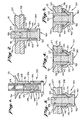
- the blind fastener shown in Figs. 1-5 is the same as the fastener of the present invention shown in Figs. 6-10 except that the collar (described below) is missing and such missing element not only results in a major change in the construction of the blind fastener but also causes a major change in its operation particularly during installation to achieve a large bearing surface on the blind side without damage to the blind side. It should be noted that a blind fastener similar to that shown in Figs.
- the blind fastener 20 comprises a nut 21, a bolt 30 and a sleeve 40.
- the nut 21 has a body 22 with an axial bore 23 therethrough.
- the mean diameter (when threaded) of the bore 23 is about 55% to 70% of the external diameter of the body 22.
- a nose 24 bearing a conically shaped chamfer 25 at an angle of about 15° to 30° to the axis of the nut 21.
- an enlarged head 26 adapted to seat against the open side of the parts 27 and 28 being fastened.
- the length of the nut 21 is adapted to extend the external surface 29 of the body 22 beyond the blind side of the parts being fastened even in the maximum grip situation by a distance sufficient to permit the thin wall section 42 of the sleeve 40 to adapt to the external surface 29 of a nut body 22. As described below, such adaptation differs substantially depending on whether or not the collar 50 is present.
- the bolt 30 has a stem 31 extending through the nut 21 and an enlarged head 32 adjacent to the nut nose 24.
- the diameter of the head 32 is customarily equal to the diameter of the nut body .22.
- a breakneck 33 adapted to fracture when a preselected stress is applied to the bolt stem 31 during installation of the blind fastener 20. Such fracture is designed to occur when the breakneck is located flush with or slightly above the open side of the parts being fastened by the blind fastener upon completion of the installation of the blind fastener.
- a sleeve 40 On the bolt stem 31 between the nut nose 24 and the bolt head 32 is a sleeve 40 having a thick wall section 41 adjacent to the bolt head 32 and a thin wall section 42 adjacent to the nut nose 24 formed by a recess 43 in said thin wall section 42.
- the length of the thin wall section 42 of the sleeve 40 is about 20% to 50% of the length of the sleeve 40 and preferably is about 30% to 45% of the length of the sleeve 40.
- the wall thickness of the thin wall section 42 of the sleeve 40 is about 5% to 20% of the outside diameter of the sleeve 40.
- the thickness of the thin wall section 42 is about 50% to 70% of the thickness of the thick wall section 41.
- Between the thick wall section 41 and thin wall section 42 is a shoulder 44.
- the external diameter of the sleeve 40 is customarily equal to the diameter of the nut body 22.
- FIG. 2-5 The operation during installation of the fastener shown in Fig. 1 is illustrated in Fig. 2-5.
- Fig. 2-5 As illustrated in Fig. 2, as the bolt 30 is drawn into the nut 21, the free end 45 of the thin wall section 42 contacts the chamfer 25 of the nut nose 24 and is expanded outwardly thereby.
- Fig. 3 upon further drawing of the bolt 30 into the nut 21, the thin wall section 42 of the sleeve 40 progresses along the body 22 of the nut 21 and conforms to the external surface 29 of the body 22 so that the thin wall section 42 in effect becomes a hollow cylindrical column co-axial with the body 22 of the nut 21. Consequently, when the free end 45 of the thin wall section 42 contacts the blind side of part 28 frequently the situations illustrated in Figs.
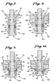
- the blind fastener of the present invention is the same as the blind fastener shown and described in Fig. 1 except that it includes a collar 50 on the bolt stem 31 between the nut nose 24 and sleeve 40 which collar 50 has a tensile strength very much less than the tensile strength of the sleeve 40.
- the sleeve 40 is adapted upon the setting of the blind fastener 20 to initially expand its thin wall section 42 over the nut 21 with the collar 50 therebetween. Then the free end 45 of the thin wall section 42 tapers inwardly towards the nut body 22. Finally the thin wall section 42 buckles outwardly upon contact with the part 28 to form a large bearing surface on the blind side of part 28.
- the collar 50 is initially set in the thin wall recess 43 and is the same length as the thin wall recess 43; however, depending on the relative tensile strength of the collar 50 and the sleeve 40 the length of the collar 50 may be between about 50% and 100% of the length of the thin wall recess 43.
- the tensile strength of the collar material can be about 5% to 30% of the tensile strength of the sleeve material but is preferably about 10% to 20% of the tensile strength of the sleeve material.
- Figs. 8-10 The operation of the blind fastener 20 of the present invention is illustrated in Figs. 8-10. As shown in Fig. 8, (similar to Fig. 2) as the bolt 30 is drawn into the nut 21 the collar 50 adjoining the free end 45 of the thin wall section 42 contacts the chamfer 25 of the nut nose 24 and causes the free end 45 to expand outwardly. As illustrated in Fig. 9, (unlike Fig.
- the collar 50 and thin wall section 42 proceed over the body 22 of the nut 21, however, because of the stress applied by the high tensile strength thin wall section 42 to the low tensile strength collar 50, the free end 45 of the thin wall section 42 tapers inwardly toward the external surface 29 of the body 22 displacing a portion of the collar 50 but does not become aligned with the body 22. Consequently, unlike the situation shown in Fig. 3, the thin wall section 42 does not conform to the external surface 29 of the body 22 but rather assumes a buckling mode which curves substantially at the free end 45 adjacent to the blind side of the part 28. Consequently, as shown in Fig.
- the thin wall section 42 buckles outwardly without substantial pressure being applied by the free end 45 to the blind side of the part 28 and with a uniform large bearing surface approximately circular in shape and having a diameter of about 150% to 200% of the external diameter of the nut body 22.
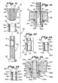
- an alternate embodiment of the present invention includes an unthreaded nut and bolt with the bolt stem 31a having a groove section 34 adjoining the end 35 remote from the bolt head 32a which groove section is adapted to be grasped by an installation tool (not shown) and the bolt thereby pulled into the nut during installation in a manner well known to the prior art.
- Such alternate embodiment of the fastener of the present invention preferably includes a locking ring 36 on the bolt stem which upon installation seats in a locking groove 37 in the bolt stem 31a and in a recess 38 in the nut head 26 such as those described in U.S. Patent No.
- the sleeve 140 and the collar 150 may be separate elements mounted in the same relative positions on the bolt stem 31.
- the free end 146 of the thick wall section 141 has a chamfer 147 at an angle of about 20° to 30° from the axis of the sleeve 140 to minimize the tuck out of the sleeve 140 when forced into contact with the bolt head.
- FIGs. 13 and 14 Still other embodiments of the nut and sleeve of the present invention are shown in Figs. 13 and 14 where adjacent the free ends 246 and 346, respectively, of the thick wall sections 241 and 341, respectively, are reduced wall sections 248 and 348, respectively.
- the reduced wall section 248 is formed by a groove 249 in the exterior surface of the thick wall section 241 of the sleeve 240.
- the reduced wall section 348 in sleeve 340 is formed by a recess 349 in the free end 346 of thick wall section 341.
- the length of the reduced wall sections 248 and 348 are about 20% to 50% of sleeves 240 and 340, respectively, and preferably are about 30% to 45% of the length of the respective sleeves 240 and 340.
- the wall thickness of the reduced wall sections 248 and 348 of the respective sleeves 240 and 340 are each about 10% to 30% of the outside diameter of the respective sleeves 240 and 340. As illustrated in Fig. 13, the reduced wall section need not be adjoining the free end.
- the alternate embodiment of the present invention such as those illustrated in Figs. 13 and 14 involve the free end of the thick wall section of the sleeve being adapted to buckle to permit flush breakoff of the bolt stem throughout the fastener grip range.
- such selective buckling may be achieved by a reduced wall section either by a groove in the external surface or a recess in the sleeve bore.
- such selective buckling permits the uniform large bearing surface on the blind side of the part 328 and in addition, permits additional buckling adjacent to the bolt head for a portion of the sleeve 340 to accommodate unequal thicknesses on the blind side of the parts, being fastened.
- Still other embodiments of the present invention may include selectively annealing the thin wall section of the sleeve to reduce further its tensile strength to permit buckling at a desired level of applied force.
- the thick wall section may be selectively annealed with or without a reduced wall portion to reduce its tensile strength to provoke buckling to permit flush breakoff throughout the fastener grip range.
- the major dimensions of a specific example (MBF2013-6-100 130° flush shear head) of the blind fastener of the present invention are as follows:
- the nut may be made of Ti-6A1-4V titanium alloy or A-286 stainless steel.
- the nut may utilize a variety of head styles such as the flush head defined in AN 509, MS 20426, NAS 1097 or a protruding head with driving recess as defined in NAS 1669.
- the bolt made may be made out of the same materials as the nut.
- the sleeve may be made out of materials such as A-286 or 304 stainless steel.
- the collar is preferably made out of low tensile strength plastic materials such as Delrin, Celcon, Teflon, Nylon or fiberglass reinforced versions of the above; however, softened material such as aluminum, copper and nickel may be utilized provided that the tensile strength of the sleeve is sufficiently larger than the tensile strength of the collar as discussed above.
- a specific example of a set of materials is that the nut, bolt and sleeve are composed of A-286 stainless steel (tensile strength of nut and bolt approximately 12,600 Kg/sq. cm. (180 KSI) and tensile strength of sleeve approximately 5,250 Kg/Sq. cm. (75 KSI) and the collar composed of Delrin acetal rod (tensile strength 560 to 840 Kg/Sq. cm. (8 to 12 KSI).
- One feature of the present invention is a blind fastener which can have an installed collar but achieves a large uniform bearing surface on the blind side without substantially damaging the blind side.
- Still another feature of the present invention is a blind fastener which achieves a large bearing surface on the blind side but is less expensive, lighter, easier to fabricate, and has shorter blind side protrusion than comparable large bearing surface blind fasteners.
- Still another feature of the present invention is a blind fastener which has a combination of a sleeve with a thin wall section adjacent to the nut on the blind side and a collar adjoining such thin wall section which collar has a tensile strength very much less than the tensile strength of said sleeve so that upon the installation, the free end of the thin wall section tapers inwardly toward said nut and the thin wall section buckles easily upon contact with the surface on the blind side.
- Still another feature of the present invention is a blind fastener wherein the free end of the thick wall section of the sleeve is adapted to buckle to permit the flush breakoff throughout the fastener grip range.
Landscapes
- Engineering & Computer Science (AREA)
- General Engineering & Computer Science (AREA)
- Mechanical Engineering (AREA)
- Dowels (AREA)
- Insertion Pins And Rivets (AREA)
- Slide Fasteners, Snap Fasteners, And Hook Fasteners (AREA)
Applications Claiming Priority (2)
| Application Number | Priority Date | Filing Date | Title |
|---|---|---|---|
| US06/253,783 US4457652A (en) | 1981-04-13 | 1981-04-13 | Composite buckling blind fastener |
| US253783 | 1994-06-03 |
Publications (2)
| Publication Number | Publication Date |
|---|---|
| EP0063181A1 EP0063181A1 (en) | 1982-10-27 |
| EP0063181B1 true EP0063181B1 (en) | 1985-04-24 |
Family
ID=22961686
Family Applications (1)
| Application Number | Title | Priority Date | Filing Date |
|---|---|---|---|
| EP81110379A Expired EP0063181B1 (en) | 1981-04-13 | 1981-12-11 | Composite buckling blind fastener |
Country Status (9)
| Country | Link |
|---|---|
| US (1) | US4457652A (da) |
| EP (1) | EP0063181B1 (da) |
| JP (1) | JPS57171105A (da) |
| BR (1) | BR8201703A (da) |
| CA (1) | CA1170485A (da) |
| DE (1) | DE3170207D1 (da) |
| DK (1) | DK150358C (da) |
| ES (1) | ES273350Y (da) |
| IL (1) | IL64528A (da) |
Families Citing this family (70)
| Publication number | Priority date | Publication date | Assignee | Title |
|---|---|---|---|---|
| US4579491A (en) * | 1981-12-28 | 1986-04-01 | Sps Technologies | Blind fastener assembly |
| US4877362A (en) * | 1982-06-04 | 1989-10-31 | Microdot Inc. | Sheathed composite blind rivet |
| US4595324A (en) * | 1982-09-28 | 1986-06-17 | Monogram Industries, Inc. | Impulse resistant blind fastener |
| IL74235A0 (en) * | 1984-08-08 | 1985-05-31 | Monogram Ind Inc | Improved composite blind fastener |
| GB2168122A (en) * | 1984-12-04 | 1986-06-11 | Avdel Ltd | Blind fastener |
| GB8430516D0 (en) * | 1984-12-04 | 1985-01-09 | Avdel Ltd | Blind fastener |
| DE3446516A1 (de) * | 1984-12-20 | 1986-06-26 | Hilti Ag, Schaan | Spreizduebel fuer duennwandige bauteile |
| US4859128A (en) * | 1985-04-26 | 1989-08-22 | Microdot Inc. | Sheathed composite blind rivet |
| IL79142A0 (en) * | 1985-06-24 | 1986-09-30 | Goodrich Co B F | Blind fastener |
| US4681494A (en) * | 1985-10-04 | 1987-07-21 | Monogram Industries, Inc. | Drive nut blend fastener with cap nut |
| DE3607607A1 (de) * | 1986-03-07 | 1987-09-17 | Braas & Co Gmbh | Befestigung von dichtungsbahnen und/oder daemmplatten am flachdach und dafuer bestimmte befestigungseinrichtung |
| US4767248A (en) * | 1986-03-18 | 1988-08-30 | Monogram Industries, Inc. | Fastener for securing panels of composite materials |
| US4807498A (en) * | 1986-10-21 | 1989-02-28 | Sps Technologies, Inc. | Blind fastener installation tool and modified fastener |
| US4832548A (en) * | 1987-03-02 | 1989-05-23 | Sps Technologies, Inc. | Blind fastener for composite material |
| US4836062A (en) * | 1987-03-11 | 1989-06-06 | Lok-Fast, Inc. | Universal tool adaptes for blind fastener installation tools and a universal method for installation of blind fasteners |
| GB2202293A (en) * | 1987-03-19 | 1988-09-21 | Avdel Ltd | Releasable rivets |
| US4968198A (en) * | 1987-05-26 | 1990-11-06 | Binns Lloyd Sylvester | Buckling sleeve blind fastener |
| US4900205A (en) * | 1988-08-15 | 1990-02-13 | Huck Manufacturing Co. | Blind fastener forming a blind head with a large effective area |
| FR2647166B1 (fr) * | 1989-05-19 | 1991-07-12 | Garonne Ets Auriol & Cie | Organe de rivetage aveugle, procede d'assemblage et assemblages obtenus |
| US4950115A (en) * | 1989-10-02 | 1990-08-21 | Huck Manufacturing Company | Blind fastener with expandable sleeve forming a blind bulbed head with large bearing area and a pin having a controlled protrusion length |
| JPH0432309U (da) * | 1990-07-13 | 1992-03-16 | ||
| US5256017A (en) * | 1990-12-06 | 1993-10-26 | P/O Normal | Composite blind rivet assembly |
| US5213460A (en) * | 1991-05-24 | 1993-05-25 | Huck International, Inc. | High strength blind bolt with uniform high clamp over an extended grip range |
| US5178502A (en) * | 1991-05-24 | 1993-01-12 | Huck International, Inc. | High strength blind bolt |
| US5152648A (en) * | 1991-11-06 | 1992-10-06 | Textron Inc. | Blind fastener for composite materials |
| US5350264A (en) * | 1993-03-26 | 1994-09-27 | Monogram Aerospace Fasteners, Inc. | Blind fastener with reinforced containment sleeve |
| US5498110A (en) * | 1994-02-25 | 1996-03-12 | Monogram Aerospace Fasteners | Blind fastener with deformable sleeve |
| US5603592A (en) * | 1994-10-03 | 1997-02-18 | Huck International, Inc. | High strength blind bolt with uniform high clamp over an extended grip range |
| US5947667A (en) * | 1995-11-07 | 1999-09-07 | The Boeing Company | Structural blind fastener |
| US5816761A (en) * | 1996-01-11 | 1998-10-06 | The Boeing Company | Lightweight structural blind fastener |
| US5810530A (en) * | 1997-10-08 | 1998-09-22 | Huck International, Inc. | Interference blind type bolt |
| US6036418A (en) * | 1998-08-12 | 2000-03-14 | Monogram Aerospace Fasteners, Inc. | Self-expanding blind fastener with mechanical lock |
| ATE429587T1 (de) * | 1999-12-10 | 2009-05-15 | Novator Ab | Befestigungsvorrichtung und verfahren zum befestigen eines verbundlaminats |
| US6454502B1 (en) | 2000-09-13 | 2002-09-24 | Fairchild Holding Corp. | Blind fastener and drive nut assembly |
| US6676347B2 (en) | 2000-09-13 | 2004-01-13 | Huck Patents, Inc. | Blind fastener and drive nut assembly |
| GB2388412A (en) * | 2002-05-08 | 2003-11-12 | Emhart Llc | Blind rivet |
| US6868757B2 (en) | 2003-05-20 | 2005-03-22 | Huck International, Inc. | Blind fastener and nose assembly for installation of the blind fastener |
| US20050163586A1 (en) * | 2004-01-05 | 2005-07-28 | Tamashiro Emory K. | Flush break-off blind bolt |
| US7150594B2 (en) * | 2004-03-09 | 2006-12-19 | The Boeing Company | Hybrid fastener apparatus and method for fastening |
| US20060062650A1 (en) * | 2004-09-20 | 2006-03-23 | The Boeing Company | Hybrid fastener apparatus and method for fastening |
| AU2007204888B2 (en) | 2006-01-11 | 2012-08-16 | Fatigue Technology, Inc. | Bushing kits, bearings, and methods of installation |
| US8517649B2 (en) | 2006-10-05 | 2013-08-27 | Monogram Aerospace Fasteners, Inc. | Dual-action disposable clamp |
| US8398345B2 (en) * | 2006-10-05 | 2013-03-19 | Monogram Aerospace Fasteners, Inc. | Low profile dual-action disposable clamp |
| US8511952B2 (en) * | 2006-10-05 | 2013-08-20 | Monogram Aerospace Fasteners, Inc. | Dual-action disposable clamp |
| US20110038688A1 (en) * | 2007-05-15 | 2011-02-17 | Fatigue Technology ,Inc. a corporation | Blind installed expandable collar and threaded inner member |
| US7966711B2 (en) * | 2007-08-14 | 2011-06-28 | The Boeing Company | Method and apparatus for fastening components using a composite two-piece fastening system |
| WO2009055298A2 (en) | 2007-10-22 | 2009-04-30 | Monogram Aerospace Fasteners, Inc. | Blind fastener |
| US8393068B2 (en) * | 2007-11-06 | 2013-03-12 | The Boeing Company | Method and apparatus for assembling composite structures |
| WO2009111745A2 (en) | 2008-03-07 | 2009-09-11 | Fatigue Technology, Inc. | Expandable member with wave inhibitor and methods of using the same |
| WO2009146058A2 (en) | 2008-04-02 | 2009-12-03 | Monogram Aerospace Fasteners, Inc. | Flush-mount, blind fastener |
| US8128330B2 (en) * | 2008-08-01 | 2012-03-06 | Varian Semiconductor Equipment Associates, Inc. | Fastening apparatus |
| US8636455B2 (en) | 2009-04-10 | 2014-01-28 | Fatigue Technoloy, Inc. | Installable assembly having an expandable outer member and a fastener with a mandrel |
| FR2947597A1 (fr) * | 2009-07-06 | 2011-01-07 | Lisi Aerospace | Procede de freinage d'un ecrou en materiau a faible capacite de deformation plastique |
| WO2011084624A2 (en) | 2009-12-16 | 2011-07-14 | Fatigue Technology, Inc. | Modular nut plate assemblies and methods of using the same |
| FR2957827B1 (fr) * | 2010-03-26 | 2012-06-15 | Eris | Organe de rivetage et outil de pose adapte |
| US9212678B2 (en) | 2011-04-14 | 2015-12-15 | John D. Pratt | Fastener and method of installing same |
| WO2012167136A2 (en) | 2011-06-03 | 2012-12-06 | Fatigue Technology, Inc. | Expandable crack inhibitors and methods of using the same |
| EP2721311B1 (en) | 2011-06-15 | 2018-03-14 | Fatigue Technology, Inc. | Modular nut plates with closed nut assemblies |
| US8961086B2 (en) | 2011-09-14 | 2015-02-24 | John D. Pratt | Fastener and method of installing same |
| WO2013043673A1 (en) | 2011-09-19 | 2013-03-28 | Monogram Aerospace Fasteners. Inc. | Blind fastener with removable wrenching means and method of removing the wrenching means |
| US8938886B2 (en) | 2012-01-30 | 2015-01-27 | Fatigue Technology, Inc. | Smart installation/processing systems, components, and methods of operating the same |
| US9284971B2 (en) * | 2012-04-04 | 2016-03-15 | John D. Pratt | Fastener and method of installing same |
| US9593706B2 (en) | 2012-11-11 | 2017-03-14 | The Boeing Company | Structural blind fastener and method of installation |
| FR3009354B1 (fr) * | 2013-08-05 | 2016-02-05 | Lisi Aerospace | Dispositif de fixation de structure |
| EP3009695B1 (en) | 2014-10-13 | 2018-05-02 | Monogram Aerospace Fasteners, Inc. | Deformable sleeve nut and a method of manufacturing |
| EP3284959B1 (en) | 2016-03-18 | 2020-02-12 | Monogram Aerospace Fasteners, Inc. | Blind fastener |
| US10920812B2 (en) | 2017-03-09 | 2021-02-16 | Centrix Inc. | Fastener system with expandable ring |
| FR3085448B1 (fr) * | 2018-09-04 | 2020-11-27 | Lisi Aerospace | Vis avec gorge de rupture, fixation comprenant une telle vis, assemblage et procede d'installation associes |
| CN111963541B (zh) * | 2020-08-19 | 2022-04-01 | 中国航空工业集团公司沈阳飞机设计研究所 | 一种飞机结构连接组件 |
| GB2600415A (en) * | 2020-10-27 | 2022-05-04 | Airbus Operations Ltd | Blind fastener |
Family Cites Families (6)
| Publication number | Priority date | Publication date | Assignee | Title |
|---|---|---|---|---|
| GB1178655A (en) * | 1968-08-02 | 1970-01-21 | Anthony Wayland Moore | Rivets and method of Riveting |
| US3657955A (en) * | 1970-05-14 | 1972-04-25 | Thomas L Mckay | Blind fastener with expandable collar |
| US4237768A (en) * | 1976-11-05 | 1980-12-09 | Hi-Shear Corporation | Blind fastener |
| US4203346A (en) * | 1977-06-13 | 1980-05-20 | Vsi Corporation | Blind bolt fastener for low bearing strength materials |
| US4142439A (en) * | 1977-08-29 | 1979-03-06 | Sps Technologies, Inc. | Blind fastener assembly |
| US4312613A (en) * | 1979-05-11 | 1982-01-26 | Binns Lloyd Sylvester | Blind rivet assembly |
-
1981
- 1981-04-13 US US06/253,783 patent/US4457652A/en not_active Expired - Lifetime
- 1981-12-11 EP EP81110379A patent/EP0063181B1/en not_active Expired
- 1981-12-11 IL IL64528A patent/IL64528A/xx not_active IP Right Cessation
- 1981-12-11 DE DE8181110379T patent/DE3170207D1/de not_active Expired
- 1981-12-16 CA CA000392404A patent/CA1170485A/en not_active Expired
- 1981-12-23 JP JP56207239A patent/JPS57171105A/ja active Granted
-
1982
- 1982-02-10 DK DK057082A patent/DK150358C/da not_active IP Right Cessation
- 1982-03-17 ES ES1982273350U patent/ES273350Y/es not_active Expired
- 1982-03-25 BR BR8201703A patent/BR8201703A/pt not_active IP Right Cessation
Also Published As
| Publication number | Publication date |
|---|---|
| IL64528A0 (en) | 1982-03-31 |
| IL64528A (en) | 1986-01-31 |
| BR8201703A (pt) | 1983-02-16 |
| DK57082A (da) | 1982-10-14 |
| DE3170207D1 (en) | 1985-05-30 |
| EP0063181A1 (en) | 1982-10-27 |
| JPS6139527B2 (da) | 1986-09-04 |
| JPS57171105A (en) | 1982-10-21 |
| CA1170485A (en) | 1984-07-10 |
| ES273350Y (es) | 1984-11-16 |
| ES273350U (es) | 1984-04-01 |
| DK150358B (da) | 1987-02-09 |
| DK150358C (da) | 1987-11-23 |
| US4457652A (en) | 1984-07-03 |
Similar Documents
| Publication | Publication Date | Title |
|---|---|---|
| EP0063181B1 (en) | Composite buckling blind fastener | |
| US4950115A (en) | Blind fastener with expandable sleeve forming a blind bulbed head with large bearing area and a pin having a controlled protrusion length | |
| US4595324A (en) | Impulse resistant blind fastener | |
| US4900205A (en) | Blind fastener forming a blind head with a large effective area | |
| CA2183450C (en) | Blind fastener with deformable sleeve | |
| US4609315A (en) | Corrosion resistant dual tapered head fastener and panel composite | |
| US5125778A (en) | Fit up swage fastener with a variable and selectively high initial clamp pre-load and method | |
| US4627775A (en) | Blind fastener with grip compensating means | |
| EP0331775B1 (en) | Blind fastener for composite material | |
| AU579733B2 (en) | Expansion type anchor bolt | |
| US4921384A (en) | Swage fasteners with a high stand-off collar | |
| US3277771A (en) | Blind fastener with locking collar | |
| US5810530A (en) | Interference blind type bolt | |
| US5256017A (en) | Composite blind rivet assembly | |
| US4846611A (en) | Fastening system and fastener for shipping containers and the like | |
| US4767248A (en) | Fastener for securing panels of composite materials | |
| EP0497455A1 (en) | Self-plugging blind rivet | |
| WO1986004965A1 (en) | Fastening system and fastener for shipping containers and the like | |
| EP0170769A1 (en) | Improved composite blind fastener | |
| US20030123947A1 (en) | Blind rivet with hollow head | |
| EP0775837B1 (en) | Blind fastener with deformable sleeve | |
| JPH0235209A (ja) | 複合材用の盲締付け子 |
Legal Events
| Date | Code | Title | Description |
|---|---|---|---|
| PUAI | Public reference made under article 153(3) epc to a published international application that has entered the european phase |
Free format text: ORIGINAL CODE: 0009012 |
|
| AK | Designated contracting states |
Designated state(s): BE DE FR GB IT NL SE |
|
| 17P | Request for examination filed |
Effective date: 19830314 |
|
| ITF | It: translation for a ep patent filed | ||
| GRAA | (expected) grant |
Free format text: ORIGINAL CODE: 0009210 |
|
| AK | Designated contracting states |
Designated state(s): BE DE FR GB IT NL SE |
|
| REF | Corresponds to: |
Ref document number: 3170207 Country of ref document: DE Date of ref document: 19850530 |
|
| ET | Fr: translation filed | ||
| PLBE | No opposition filed within time limit |
Free format text: ORIGINAL CODE: 0009261 |
|
| STAA | Information on the status of an ep patent application or granted ep patent |
Free format text: STATUS: NO OPPOSITION FILED WITHIN TIME LIMIT |
|
| 26N | No opposition filed | ||
| PGFP | Annual fee paid to national office [announced via postgrant information from national office to epo] |
Ref country code: NL Payment date: 19871231 Year of fee payment: 7 |
|
| PG25 | Lapsed in a contracting state [announced via postgrant information from national office to epo] |
Ref country code: SE Effective date: 19881212 |
|
| PG25 | Lapsed in a contracting state [announced via postgrant information from national office to epo] |
Ref country code: BE Effective date: 19881231 |
|
| BERE | Be: lapsed |
Owner name: MONOGRAM INDUSTRIES INC. Effective date: 19881231 |
|
| PG25 | Lapsed in a contracting state [announced via postgrant information from national office to epo] |
Ref country code: NL Effective date: 19890701 |
|
| NLV4 | Nl: lapsed or anulled due to non-payment of the annual fee | ||
| REG | Reference to a national code |
Ref country code: FR Ref legal event code: TP |
|
| EUG | Se: european patent has lapsed |
Ref document number: 81110379.5 Effective date: 19891205 |
|
| PGFP | Annual fee paid to national office [announced via postgrant information from national office to epo] |
Ref country code: GB Payment date: 20001107 Year of fee payment: 20 |
|
| PGFP | Annual fee paid to national office [announced via postgrant information from national office to epo] |
Ref country code: FR Payment date: 20001204 Year of fee payment: 20 |
|
| PGFP | Annual fee paid to national office [announced via postgrant information from national office to epo] |
Ref country code: DE Payment date: 20001222 Year of fee payment: 20 |
|
| PG25 | Lapsed in a contracting state [announced via postgrant information from national office to epo] |
Ref country code: GB Free format text: LAPSE BECAUSE OF EXPIRATION OF PROTECTION Effective date: 20011210 |
|
| REG | Reference to a national code |
Ref country code: GB Ref legal event code: PE20 Effective date: 20011210 |