EP0063022A1 - Improvements in or relating to flexible couplings - Google Patents
Improvements in or relating to flexible couplings Download PDFInfo
- Publication number
- EP0063022A1 EP0063022A1 EP82301802A EP82301802A EP0063022A1 EP 0063022 A1 EP0063022 A1 EP 0063022A1 EP 82301802 A EP82301802 A EP 82301802A EP 82301802 A EP82301802 A EP 82301802A EP 0063022 A1 EP0063022 A1 EP 0063022A1
- Authority
- EP
- European Patent Office
- Prior art keywords
- component
- coupling
- connector members
- connection
- coupling according
- Prior art date
- Legal status (The legal status is an assumption and is not a legal conclusion. Google has not performed a legal analysis and makes no representation as to the accuracy of the status listed.)
- Granted
Links
Images

Classifications
-
- F—MECHANICAL ENGINEERING; LIGHTING; HEATING; WEAPONS; BLASTING
- F16—ENGINEERING ELEMENTS AND UNITS; GENERAL MEASURES FOR PRODUCING AND MAINTAINING EFFECTIVE FUNCTIONING OF MACHINES OR INSTALLATIONS; THERMAL INSULATION IN GENERAL
- F16D—COUPLINGS FOR TRANSMITTING ROTATION; CLUTCHES; BRAKES
- F16D3/00—Yielding couplings, i.e. with means permitting movement between the connected parts during the drive
- F16D3/50—Yielding couplings, i.e. with means permitting movement between the connected parts during the drive with the coupling parts connected by one or more intermediate members
- F16D3/78—Yielding couplings, i.e. with means permitting movement between the connected parts during the drive with the coupling parts connected by one or more intermediate members shaped as an elastic disc or flat ring, arranged perpendicular to the axis of the coupling parts, different sets of spots of the disc or ring being attached to each coupling part, e.g. Hardy couplings
-
- F—MECHANICAL ENGINEERING; LIGHTING; HEATING; WEAPONS; BLASTING
- F16—ENGINEERING ELEMENTS AND UNITS; GENERAL MEASURES FOR PRODUCING AND MAINTAINING EFFECTIVE FUNCTIONING OF MACHINES OR INSTALLATIONS; THERMAL INSULATION IN GENERAL
- F16D—COUPLINGS FOR TRANSMITTING ROTATION; CLUTCHES; BRAKES
- F16D3/00—Yielding couplings, i.e. with means permitting movement between the connected parts during the drive
- F16D3/50—Yielding couplings, i.e. with means permitting movement between the connected parts during the drive with the coupling parts connected by one or more intermediate members
- F16D3/64—Yielding couplings, i.e. with means permitting movement between the connected parts during the drive with the coupling parts connected by one or more intermediate members comprising elastic elements arranged between substantially-radial walls of both coupling parts
- F16D3/68—Yielding couplings, i.e. with means permitting movement between the connected parts during the drive with the coupling parts connected by one or more intermediate members comprising elastic elements arranged between substantially-radial walls of both coupling parts the elements being made of rubber or similar material
Definitions
- This invention concerns improvements in or relating to flexible couplings and in particular, though not exclusively, to flexible couplings for transmitting torque between two relatively rotatable components, for example driving and driven shafts.
- Flexible couplings for transmitting-torque between two relatively rotatable components are known -comprising a plurality of rigid connector members and a plurality of resilient elastomeric elements arranged alternately to form a ring in which the connector members are adapted to be connected alternately to a respective one of the components and the load transmitting surfaces of each connector member extend parallel to the axis of rotation of the coupling whereby the elastomeric elements are loaded in compression under torque. loads and in shear under axial loads.
- the compression stiffness of the elastomeric elements is considerably greater than the shear stiffness thereof and in order to increase the axial load capacity it is known to angle the load transmitting surfaces of each connector member equally and oppositely relative to the axis of rotation of the coupling and to reverse successive connector members whereby the elastomeric elements are loaded in compression and shear under axial loads.
- a disadvantage of this construction is that under torque loads the connector members connected to one of the components are subjected to a net axial component of force in one direction and the connector members connected to the other of the components are subjected to a net axial component of force in the opposite direction whereby there is a tendency for the connector members connected to the components to move towards or away from one another.
- the invention as claimed is intended to remedy this disadvantage. It solves the problem of designing a coupling in which the load transmitting surfaces of the connector members are angled relative to the axis of rotation of the coupling so that axial loads are accommodated by the elastomeric elements in shear and compression without generating a net axial component of force acting on the connector members associated with each rotatable component under torque loads by providing an even number of connector members for attachment to each rotatable component and reversing successive connector members associated with each rotatable component.
- the main advantage offered by the invention is that torque loads do not give rise to axial forces tending to urge the connector members associated with each rotatable component towards or away from one another whilst maintaining the benefit of higher axial load capacity obtained by the angling of the load transmitting surfaces relative to the rotational axis of the coupling.
- At least four connector members adapted for connection to each rotatable component.
- each of the connector members adapted for connection to one of the rotatable components has load transmitting surfaces oppositely inclined, preferably at equal and opposite angles, relative to the axis of rotation of the coupling i.e. relatively divergent and each of the intervening connector members adapted for connection to the other rotatable component has load transmitting surfaces inclined at equal angles relative to the axis of rotation of the coupling i.e. parallel.
- each connector member may comprise a sleeve having an axially extending through bore for the passage of a bolt or similar fastening means and the connector members adapted for connection to the other rotatable component are interconnected and provided with common means for attachment of the members to the component for example each connector member may comprise a blade integral with a central hub adapted for connection to the component.
- each sleeve has relatively divergent load transmitting surfaces and each blade has parallel load transmitting surfaces.
- the load transmitting surfaces of each sleeve or blade may be planar or curved for example each blade may be of helical configuration such that the angle of inclination of the load transmitting surfaces relative to the axis of rotation increases with increase in the radial dimension of the blade although the surfaces remain parallel to one another.
- the resilient elements are precompressed to load the elements in compression to reduce or eliminate the occurrence of tensile forces therein in use. Precompression may be effected during manufacture or on assembly.
- each blade extending radially outwards from a central hub and four intervening wedge-shaped sleeves arranged such that in the unassembled condition one pair of opposed sleeves is axially offset to one side of the bladesand the other pair of opposed sleeves is axially offset by a similar amount to the other side of the blades.
- the elastomeric material between successive blades and sleeves is preloaded in compression on assembly by reducing the axial offset between the sleeves and the blades.
- each sleeve has an axially extending integral spacer portion to control the reduction in axial offset and hence the degree of precompression on assembly of the coupling.
- each blade has a pair of resilient stops, one at each axial end thereof, to control axial movement between the blades and sleeves beyond a predetermined value.
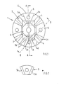
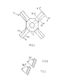
- the coupling 1 shown in Figures 1 to 8 of the accompanying drawings includes a spider 2 having a central hub 3 for securing the spider to one of two relatively rotatable components (not shown) and four circumferentially spaced radially and axially extending blades 4 each having a pair of load transmitting surfaces 4a.
- Alternating with the blades 4 are four rigid connector sleeves 5 each having an axially extending bore 6 for securing the sleeve e.g. by means of a bolt (not shown) to the other of said two relatively rotatable components (not shown) and a pair of load transmitting surfaces 5a.
- a respective resilient rubber element 7 Extended between and bonded to each pair of confronting circum- f erentially facing load transmitting surfaces 4a and 5a of a blade 4 and sleeve 5 respectively.
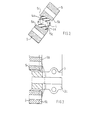
- Each sleeve 5 is wedge-shaped in transverse cross-section and the associated load transmitting surfaces 5a are inclined at equal and opposite angles relative to the rotational axis of the coupling i.e. the surfaces 5a are relatively divergent in the axial direction from one end of the sleeve towards the other end ( Figure 7).
- Each sleeve 5 is formed at the narrower end thereof with an integral axially extending spacer portion 5b and successive sleeves 5 are reversed so that the associated circumferentially facing surfaces 5a are relatively divergent towards opposite end faces of the coupling ( Figures 2, 3 and 8).
- Each blade 4 is of helical configuration and the associated load transmitting surfaces 4a are inclined at equal angles relative to the rotational axis of the coupling i.e. the surfaces are parallel.
- the angle of inclination of the surfaces 4a is not constant in the radial direction of the blade but, due to the helical profile of the blade, increases relative to the rotational axis of the coupling with increase in the radial dimension of the blade although the surfaces 4a are parallel at any given radial position, Successive blades are of opposite hand i.e. the gap therebetween either increases or. decreases in the axial direction of the coupling from one end towards the other to accommodate the intervening wedge-shaped sleeve 5.
- Figure 8 shows the above-described coupling in the unloaded free condition in which successive sleeves 5 and intervening blade 4 are axially offset with one pair of opposed sleeves being axially offset to one side of the blade and the other pair of opposed sleeves being axially offset to the other side.
- the rubber elements 7 are moulded to extend over the end faces of the blades 4 to provide resilient stops 8.
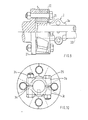
- FIG. 9 to 12 there is shown an installation in which the above-described coupling 1 is used to connect a boat propellor shaft 20 to a flexibly mounted engine (not shown).
- the coupling 1 is positioned between an annular engine gear box flange 21 and an annular stop plate 22 having a central aperture 23 through which the hub 3 of the spider 2 extends.
- the flange 21 and plate 22 are each formed with four apertures 21a and 22a respectively andeach sleeve bore 6 is aligned with a pair of corresponding apertures 21a and 22a.
- On assembly each sleeve 5 is bolted to the flange 21 by a nut and bolt assembly 24.
- the stop plate 22 is drawn towards the flange 21 so as to.reduce the axial offset between the sleeves 5 and blades 4 from that which exists in the unloaded free condition of the coupling ( Figure 8) and preload the rubber elements? in compression.
- the reduction in axial offset is determined by the axial length of the sleeves 5 and in particular by the axial length of the integral spacer portions 5b thereof which may be selected to produce any desired degree of preloading.
- An axially extending slot 3a divides the free end of the spider hub 3 into two halves 3a, 3b o
- the hub 3 is clamped to the shaft 20 by inserting the end of the shaft in the free end of the hub 3 and drawing the two hub halves together by means of a pair of nut and bolt assemblies 25.
- axial loads in either direction are accommodated by the rubber elements 7 in compression and shear up to a predetermined value whereupon the blade end stops 8 contact either the stop plate 22 or gear box flange 21 to restrict further axial movement between the blades and sleeves thereby preventing over load of the elements 7.
- Torque loads in either direction are also accommodated by the rubber elements 7 in compression and shear but unlike the known couplings in which the load transmitting surfaces of the connector members are inclined relative to the rotational axis of the coupling the transmission of torque loads by the coupling according to the present invention is not accompanied by any tendency for the connector members connected to each of the components to move towards or away from one another in the axial direction.
- each blade may have flat load transmitting surfaces which may be inclined at the same angle as the confronting load transmitting surface of the adjacent sleeve so as to be parallel thereto.
- Each sleeve may have curved load transmitting surfaces and may have a helical configuration similar to the load transmitting surface of the adjacent blade.
- the number of blades and sleeves may be varied provided there is an even number of each, i.e. multiples of two of each and preferably a minimum of four of each.
- Each sleeve may have an integral spacer portion as described or a separate spacer may be used on assembly the size of which may be selected to provide the required degree of pre-loading of the resilient elements.
- pre-loading of the resilient elements may be effected by any other means known to those skilled in the art.
- the spider may have a slotted hub as described to facilitate clamping of the hub to a shaft or the hub may be attached by any other suitable means e.g. radially extending bolts.
- the resilient elements may be made of any suitable elastomer and may include a reinforcement.
Abstract
Description
- This invention concerns improvements in or relating to flexible couplings and in particular, though not exclusively, to flexible couplings for transmitting torque between two relatively rotatable components, for example driving and driven shafts.
- Flexible couplings for transmitting-torque between two relatively rotatable components are known -comprising a plurality of rigid connector members and a plurality of resilient elastomeric elements arranged alternately to form a ring in which the connector members are adapted to be connected alternately to a respective one of the components and the load transmitting surfaces of each connector member extend parallel to the axis of rotation of the coupling whereby the elastomeric elements are loaded in compression under torque. loads and in shear under axial loads.
- The compression stiffness of the elastomeric elements is considerably greater than the shear stiffness thereof and in order to increase the axial load capacity it is known to angle the load transmitting surfaces of each connector member equally and oppositely relative to the axis of rotation of the coupling and to reverse successive connector members whereby the elastomeric elements are loaded in compression and shear under axial loads.
- A disadvantage of this construction however is that under torque loads the connector members connected to one of the components are subjected to a net axial component of force in one direction and the connector members connected to the other of the components are subjected to a net axial component of force in the opposite direction whereby there is a tendency for the connector members connected to the components to move towards or away from one another.
- The invention as claimed is intended to remedy this disadvantage. It solves the problem of designing a coupling in which the load transmitting surfaces of the connector members are angled relative to the axis of rotation of the coupling so that axial loads are accommodated by the elastomeric elements in shear and compression without generating a net axial component of force acting on the connector members associated with each rotatable component under torque loads by providing an even number of connector members for attachment to each rotatable component and reversing successive connector members associated with each rotatable component.
- The main advantage offered by the invention is that torque loads do not give rise to axial forces tending to urge the connector members associated with each rotatable component towards or away from one another whilst maintaining the benefit of higher axial load capacity obtained by the angling of the load transmitting surfaces relative to the rotational axis of the coupling.
- Preferably there are at least four connector members adapted for connection to each rotatable component.
- Preferably each of the connector members adapted for connection to one of the rotatable components has load transmitting surfaces oppositely inclined, preferably at equal and opposite angles, relative to the axis of rotation of the coupling i.e. relatively divergent and each of the intervening connector members adapted for connection to the other rotatable component has load transmitting surfaces inclined at equal angles relative to the axis of rotation of the coupling i.e. parallel.
- Preferably the connector members adapted for connection to one of the rotatable components are separate and provided with respective means for attachment of the member to the component for example each connector member may comprise a sleeve having an axially extending through bore for the passage of a bolt or similar fastening means and the connector members adapted for connection to the other rotatable component are interconnected and provided with common means for attachment of the members to the component for example each connector member may comprise a blade integral with a central hub adapted for connection to the component.
- Preferably each sleeve has relatively divergent load transmitting surfaces and each blade has parallel load transmitting surfaces. The load transmitting surfaces of each sleeve or blade may be planar or curved for example each blade may be of helical configuration such that the angle of inclination of the load transmitting surfaces relative to the axis of rotation increases with increase in the radial dimension of the blade although the surfaces remain parallel to one another.
- Preferably the resilient elements are precompressed to load the elements in compression to reduce or eliminate the occurrence of tensile forces therein in use. Precompression may be effected during manufacture or on assembly.
- In one preferred construction there are four blades extending radially outwards from a central hub and four intervening wedge-shaped sleeves arranged such that in the unassembled condition one pair of opposed sleeves is axially offset to one side of the bladesand the other pair of opposed sleeves is axially offset by a similar amount to the other side of the blades. In consequence the elastomeric material between successive blades and sleeves is preloaded in compression on assembly by reducing the axial offset between the sleeves and the blades. Preferably each sleeve has an axially extending integral spacer portion to control the reduction in axial offset and hence the degree of precompression on assembly of the coupling. Preferably each blade has a pair of resilient stops, one at each axial end thereof, to control axial movement between the blades and sleeves beyond a predetermined value.
- The invention will now be described in more detail, by way of example only, with reference to the accompanying drawings wherein:
- Figure 1 is an end view of a coupling according to the present invention;
- Figures 2 and 3 are sections on the lines 2-2 and 3-3 respectively of Figure 1;
- Figure 4 is an end view of the spider of the coupling shown in Figure 1;
- Figures 5 and 6 are sections on the lines 5-5 and 6-6 respectively of Figure 4;
- Figure 7 is an end view of one of the connector sleeves of the coupling shown in Figure 1;
- Figure 8 is a development of a section through the coupling of Figures 1 to 7;
- Figure 9 is a side view, partly in section, of an installation incorporating the couplings shown in Figures 1 to 8;
- Figure 10 is an end view of the installation shown in Figure 9;
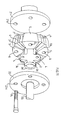
- Figure 11 is an exploded perspective view of the installation shown in Figures 9 and 10; and
- Figure 12 is a development of a section through the assembled coupling of Figures 9 and 10.
- The
coupling 1 shown in Figures 1 to 8 of the accompanying drawings includes aspider 2 having acentral hub 3 for securing the spider to one of two relatively rotatable components (not shown) and four circumferentially spaced radially and axially extendingblades 4 each having a pair of load transmitting surfaces 4a. Alternating with theblades 4 are fourrigid connector sleeves 5 each having an axially extendingbore 6 for securing the sleeve e.g. by means of a bolt (not shown) to the other of said two relatively rotatable components (not shown) and a pair ofload transmitting surfaces 5a. Extended between and bonded to each pair of confronting circum- ferentially facingload transmitting surfaces 4a and 5a of ablade 4 andsleeve 5 respectively is a respectiveresilient rubber element 7. - Each
sleeve 5 is wedge-shaped in transverse cross-section and the associatedload transmitting surfaces 5a are inclined at equal and opposite angles relative to the rotational axis of the coupling i.e. thesurfaces 5a are relatively divergent in the axial direction from one end of the sleeve towards the other end (Figure 7). Eachsleeve 5 is formed at the narrower end thereof with an integral axially extendingspacer portion 5b andsuccessive sleeves 5 are reversed so that the associated circumferentially facingsurfaces 5a are relatively divergent towards opposite end faces of the coupling (Figures 2, 3 and 8). - Each
blade 4 is of helical configuration and the associated load transmitting surfaces 4a are inclined at equal angles relative to the rotational axis of the coupling i.e. the surfaces are parallel. As shown in Figures 5 and 6 the angle of inclination of the surfaces 4a is not constant in the radial direction of the blade but, due to the helical profile of the blade, increases relative to the rotational axis of the coupling with increase in the radial dimension of the blade although the surfaces 4a are parallel at any given radial position, Successive blades are of opposite hand i.e. the gap therebetween either increases or. decreases in the axial direction of the coupling from one end towards the other to accommodate the intervening wedge-shaped sleeve 5. - As shown in Figure 1 there are equal numbers of
rubber elements 7 inclined at equal and opposite angles with respect to the rotational axis of the coupling with therubber elements 7 disposed on either side of asleeve 5 adopting a generally V-shaped configuration as viewed in the axial direction. Each pair of V-shaped elements is relatively divergent from one end of the coupling towards the other end and successive pairs are reversed. - Figure 8 shows the above-described coupling in the unloaded free condition in which
successive sleeves 5 and interveningblade 4 are axially offset with one pair of opposed sleeves being axially offset to one side of the blade and the other pair of opposed sleeves being axially offset to the other side. In addition as shown therubber elements 7 are moulded to extend over the end faces of theblades 4 to provide resilient stops 8. - Referring now to Figures 9 to 12 there is shown an installation in which the above-described
coupling 1 is used to connect aboat propellor shaft 20 to a flexibly mounted engine (not shown). - The
coupling 1 is positioned between an annular enginegear box flange 21 and anannular stop plate 22 having acentral aperture 23 through which thehub 3 of thespider 2 extends. Theflange 21 andplate 22 are each formed with fourapertures 21a and 22a respectively andeachsleeve bore 6 is aligned with a pair ofcorresponding apertures 21a and 22a. On assembly eachsleeve 5 is bolted to theflange 21 by a nut andbolt assembly 24. At the same time thestop plate 22 is drawn towards theflange 21 so as to.reduce the axial offset between thesleeves 5 andblades 4 from that which exists in the unloaded free condition of the coupling (Figure 8) and preload the rubber elements? in compression. As shown in Figure 12 the reduction in axial offset is determined by the axial length of thesleeves 5 and in particular by the axial length of theintegral spacer portions 5b thereof which may be selected to produce any desired degree of preloading. - An axially extending
slot 3a divides the free end of thespider hub 3 into twohalves hub 3 is clamped to theshaft 20 by inserting the end of the shaft in the free end of thehub 3 and drawing the two hub halves together by means of a pair of nut andbolt assemblies 25. - In use axial loads in either direction are accommodated by the
rubber elements 7 in compression and shear up to a predetermined value whereupon the blade end stops 8 contact either thestop plate 22 orgear box flange 21 to restrict further axial movement between the blades and sleeves thereby preventing over load of theelements 7. Torque loads in either direction are also accommodated by therubber elements 7 in compression and shear but unlike the known couplings in which the load transmitting surfaces of the connector members are inclined relative to the rotational axis of the coupling the transmission of torque loads by the coupling according to the present invention is not accompanied by any tendency for the connector members connected to each of the components to move towards or away from one another in the axial direction. More particularly referring to Figure 12, assume a torque load is applied to the coupling in the direction of the arrow A, an axial component of force will be generated at each of theload transmitting surfaces 4a and 5a of theblades 4 andsleeves 5 respectively which will act in the direction indicated from which it will be readily apparent that one pair of opposed blades has a net axial component of force in one direction which is equal and opposite to the net axial component of force of the other pair of opposed blades so that the resultant axial component of force acting on the spider under torque loads is zero. Likewise it will be noted that the axial component of force acting on the load transmitting surfaces of each sleeve are equal and opposite so that the resultant axial component of force acting on each sleeve under torque loads is also zero. - It will be understood the invention is not restricted to the above-described embodiment, for example the inclination of the load transmitting surfaces relative to the rotational axis of the coupling may be varied to provide any required axial and torque load capability. Each blade may have flat load transmitting surfaces which may be inclined at the same angle as the confronting load transmitting surface of the adjacent sleeve so as to be parallel thereto. Each sleeve may have curved load transmitting surfaces and may have a helical configuration similar to the load transmitting surface of the adjacent blade.
- The number of blades and sleeves may be varied provided there is an even number of each, i.e. multiples of two of each and preferably a minimum of four of each.
- Each sleeve may have an integral spacer portion as described or a separate spacer may be used on assembly the size of which may be selected to provide the required degree of pre-loading of the resilient elements. Alternatively pre-loading of the resilient elements may be effected by any other means known to those skilled in the art.
- The spider may have a slotted hub as described to facilitate clamping of the hub to a shaft or the hub may be attached by any other suitable means e.g. radially extending bolts.
- The resilient elements may be made of any suitable elastomer and may include a reinforcement.
Claims (10)
Applications Claiming Priority (2)
| Application Number | Priority Date | Filing Date | Title |
|---|---|---|---|
| GB8111332 | 1981-04-10 | ||
| GB8111332 | 1981-04-10 |
Publications (2)
| Publication Number | Publication Date |
|---|---|
| EP0063022A1 true EP0063022A1 (en) | 1982-10-20 |
| EP0063022B1 EP0063022B1 (en) | 1986-09-17 |
Family
ID=10521073
Family Applications (1)
| Application Number | Title | Priority Date | Filing Date |
|---|---|---|---|
| EP82301802A Expired EP0063022B1 (en) | 1981-04-10 | 1982-04-06 | Improvements in or relating to flexible couplings |
Country Status (9)
| Country | Link |
|---|---|
| US (1) | US4543075A (en) |
| EP (1) | EP0063022B1 (en) |
| JP (1) | JPS57179424A (en) |
| BE (1) | BE892813A (en) |
| CA (1) | CA1183008A (en) |
| DE (1) | DE3273277D1 (en) |
| DK (1) | DK156185C (en) |
| FR (1) | FR2503813B1 (en) |
| NO (1) | NO150409C (en) |
Cited By (5)
| Publication number | Priority date | Publication date | Assignee | Title |
|---|---|---|---|---|
| GB2175066A (en) * | 1985-04-01 | 1986-11-19 | Chengdu Seamless Steel | Rotary safety coupling for transmitting large torques |
| US5736122A (en) * | 1991-02-08 | 1998-04-07 | Diatide, Inc. | Technetium-99m labeled peptides for thrombus imaging |
| US5879658A (en) * | 1991-02-08 | 1999-03-09 | Diatide, Inc. | Technetium-99m labeled peptides for thrombus imaging |
| US5968476A (en) * | 1992-05-21 | 1999-10-19 | Diatide, Inc. | Technetium-99m labeled peptides for thrombus imaging |
| GB2585613A (en) * | 2019-10-09 | 2021-01-13 | Punk Couplings Ltd | Coupling |
Families Citing this family (4)
| Publication number | Priority date | Publication date | Assignee | Title |
|---|---|---|---|---|
| JPH0613596Y2 (en) * | 1987-07-07 | 1994-04-06 | 本田技研工業株式会社 | Generator support for the engine |
| JP3003784B2 (en) * | 1998-05-11 | 2000-01-31 | 株式会社シマノ | Bicycle shock absorber |
| DE102006042341A1 (en) * | 2006-09-08 | 2008-03-27 | Robert Bosch Gmbh | transmission device |
| JP5728457B2 (en) * | 2012-10-31 | 2015-06-03 | 三木プーリ株式会社 | Flexible shaft coupling and manufacturing method thereof |
Citations (3)
| Publication number | Priority date | Publication date | Assignee | Title |
|---|---|---|---|---|
| DE1174181C2 (en) * | 1958-09-25 | 1965-01-21 | Clouth Rhein Gummiwarenfabrik | Elastic connecting link, in particular for gearshift and steering rods of motor vehicles |
| FR2193444A5 (en) * | 1972-07-13 | 1974-02-15 | Freudenberg Carl | |
| FR2212880A6 (en) * | 1973-01-02 | 1974-07-26 | Dossier Michel |
Family Cites Families (16)
| Publication number | Priority date | Publication date | Assignee | Title |
|---|---|---|---|---|
| US1548629A (en) * | 1923-10-01 | 1925-08-04 | William C Durant | Cushion coupling |
| US1611558A (en) * | 1926-03-08 | 1926-12-21 | Borg & Beck Co | Driven plate for friction clutches |
| US1671436A (en) * | 1926-11-10 | 1928-05-29 | John M Melott | Flexible coupling |
| US2034001A (en) * | 1930-12-13 | 1936-03-17 | Ricefield Louis | Coupling |
| US2105702A (en) * | 1934-08-06 | 1938-01-18 | Herman J Scholtze | Flexible shaft coupling |
| US2025827A (en) * | 1934-08-11 | 1935-12-31 | Ricefield Louis | Coupling |
| US2127942A (en) * | 1936-03-20 | 1938-08-23 | Metalastik Ltd | Elastic coupling |
| FR865265A (en) * | 1940-04-27 | 1941-05-17 | Paulstra Sa | Improvements to elastic couplings |
| US2337287A (en) * | 1941-02-24 | 1943-12-21 | Alfred O Williams | Universal joint |
| AT188987B (en) * | 1954-01-30 | 1957-03-25 | Josef Schischka Fa | Elastic coupling |
| US3120745A (en) * | 1961-07-10 | 1964-02-11 | U S Universal Joints Company | Universal coupling |
| US3485062A (en) * | 1968-02-26 | 1969-12-23 | Michael P Blake | Flexible coupling |
| US3545585A (en) * | 1969-04-10 | 1970-12-08 | Proctor Silex Inc | Centrifugally interlocked coupling |
| DE2253041A1 (en) * | 1972-10-28 | 1974-05-09 | Krupp Gmbh | CLAW CLUTCH |
| FR2284796A1 (en) * | 1974-09-10 | 1976-04-09 | Paulstra Sa | Shaft coupling with elastic buffers - has set of drive fingers on muff coupling also on elastic buffer |
| US4050266A (en) * | 1975-11-21 | 1977-09-27 | Lord Corporation | Drive coupling |
-
1982
- 1982-03-30 CA CA000399782A patent/CA1183008A/en not_active Expired
- 1982-04-01 NO NO821109A patent/NO150409C/en unknown
- 1982-04-06 EP EP82301802A patent/EP0063022B1/en not_active Expired
- 1982-04-06 DE DE8282301802T patent/DE3273277D1/en not_active Expired
- 1982-04-07 DK DK163282A patent/DK156185C/en not_active IP Right Cessation
- 1982-04-08 BE BE0/207799A patent/BE892813A/en not_active IP Right Cessation
- 1982-04-08 FR FR8206147A patent/FR2503813B1/en not_active Expired
- 1982-04-09 JP JP57059466A patent/JPS57179424A/en active Granted
-
1984
- 1984-05-09 US US06/608,530 patent/US4543075A/en not_active Expired - Fee Related
Patent Citations (3)
| Publication number | Priority date | Publication date | Assignee | Title |
|---|---|---|---|---|
| DE1174181C2 (en) * | 1958-09-25 | 1965-01-21 | Clouth Rhein Gummiwarenfabrik | Elastic connecting link, in particular for gearshift and steering rods of motor vehicles |
| FR2193444A5 (en) * | 1972-07-13 | 1974-02-15 | Freudenberg Carl | |
| FR2212880A6 (en) * | 1973-01-02 | 1974-07-26 | Dossier Michel |
Cited By (8)
| Publication number | Priority date | Publication date | Assignee | Title |
|---|---|---|---|---|
| GB2175066A (en) * | 1985-04-01 | 1986-11-19 | Chengdu Seamless Steel | Rotary safety coupling for transmitting large torques |
| GB2175066B (en) * | 1985-04-01 | 1989-10-18 | Chengdu Seamless Steel | Rotary safety coupling for transmitting large torques |
| US5736122A (en) * | 1991-02-08 | 1998-04-07 | Diatide, Inc. | Technetium-99m labeled peptides for thrombus imaging |
| US5879658A (en) * | 1991-02-08 | 1999-03-09 | Diatide, Inc. | Technetium-99m labeled peptides for thrombus imaging |
| US5968476A (en) * | 1992-05-21 | 1999-10-19 | Diatide, Inc. | Technetium-99m labeled peptides for thrombus imaging |
| GB2585613A (en) * | 2019-10-09 | 2021-01-13 | Punk Couplings Ltd | Coupling |
| WO2021069897A1 (en) | 2019-10-09 | 2021-04-15 | Punk Couplings Limited | Coupling |
| GB2585613B (en) * | 2019-10-09 | 2021-08-11 | Punk Couplings Ltd | Coupling |
Also Published As
| Publication number | Publication date |
|---|---|
| US4543075A (en) | 1985-09-24 |
| CA1183008A (en) | 1985-02-26 |
| BE892813A (en) | 1982-10-08 |
| DK156185B (en) | 1989-07-03 |
| JPS57179424A (en) | 1982-11-05 |
| DK156185C (en) | 1989-11-27 |
| FR2503813B1 (en) | 1985-12-13 |
| NO821109L (en) | 1982-10-11 |
| NO150409C (en) | 1984-10-10 |
| JPH0260895B2 (en) | 1990-12-18 |
| DE3273277D1 (en) | 1986-10-23 |
| FR2503813A1 (en) | 1982-10-15 |
| DK163282A (en) | 1982-10-11 |
| EP0063022B1 (en) | 1986-09-17 |
| NO150409B (en) | 1984-07-02 |
Similar Documents
| Publication | Publication Date | Title |
|---|---|---|
| US5186686A (en) | Link and bearing for rotary coupling | |
| US3345831A (en) | Flexible couplings | |
| US4543075A (en) | Flexible couplings | |
| US4050266A (en) | Drive coupling | |
| US4708514A (en) | Resilient shaft coupling | |
| US2213277A (en) | Universal joint | |
| US3988906A (en) | Flexible coupling | |
| DE3039697C2 (en) | Coupling for the axially and radially elastic connection of the hub of the fan of a cooling fan unit with the housing of a fan drive unit | |
| US3296827A (en) | Resilient coupling | |
| US4878880A (en) | Clutch apparatus | |
| GB1583823A (en) | Hydraulic transmission drive assembly | |
| US4464140A (en) | Torque transmitting coupling | |
| US3675750A (en) | Flexible centrifugal clutch coupling | |
| US5611732A (en) | Flexible coupling with end stress relief structure | |
| US3469417A (en) | Torque transmitting coupling | |
| US4943261A (en) | Flexible shaft coupling having flexible elements interspersed between alternating attachment wedges | |
| GB2096739A (en) | Flexible couplings | |
| CA2011471A1 (en) | Reversible endless belt rotary coupling | |
| US4671780A (en) | Flexible coupling with deformable beam elements | |
| US4846761A (en) | Flexible all-steel shaft coupling | |
| JPS59144819A (en) | Flexible shaft joint | |
| US3575014A (en) | Torsionally and axially flexible coupling | |
| US3977212A (en) | Flexible coupling | |
| CA1216161A (en) | Low torsional stiffness flexible coupling | |
| US3062025A (en) | Flexible couplings |
Legal Events
| Date | Code | Title | Description |
|---|---|---|---|
| PUAI | Public reference made under article 153(3) epc to a published international application that has entered the european phase |
Free format text: ORIGINAL CODE: 0009012 |
|
| AK | Designated contracting states |
Designated state(s): DE NL SE |
|
| 17P | Request for examination filed |
Effective date: 19830419 |
|
| GRAA | (expected) grant |
Free format text: ORIGINAL CODE: 0009210 |
|
| AK | Designated contracting states |
Kind code of ref document: B1 Designated state(s): DE NL SE |
|
| REF | Corresponds to: |
Ref document number: 3273277 Country of ref document: DE Date of ref document: 19861023 |
|
| PLBE | No opposition filed within time limit |
Free format text: ORIGINAL CODE: 0009261 |
|
| STAA | Information on the status of an ep patent application or granted ep patent |
Free format text: STATUS: NO OPPOSITION FILED WITHIN TIME LIMIT |
|
| 26N | No opposition filed | ||
| PGFP | Annual fee paid to national office [announced via postgrant information from national office to epo] |
Ref country code: SE Payment date: 19910402 Year of fee payment: 10 |
|
| PGFP | Annual fee paid to national office [announced via postgrant information from national office to epo] |
Ref country code: NL Payment date: 19910430 Year of fee payment: 10 |
|
| PGFP | Annual fee paid to national office [announced via postgrant information from national office to epo] |
Ref country code: DE Payment date: 19910628 Year of fee payment: 10 |
|
| PG25 | Lapsed in a contracting state [announced via postgrant information from national office to epo] |
Ref country code: SE Effective date: 19920407 |
|
| PG25 | Lapsed in a contracting state [announced via postgrant information from national office to epo] |
Ref country code: NL Effective date: 19921101 |
|
| NLV4 | Nl: lapsed or anulled due to non-payment of the annual fee | ||
| PG25 | Lapsed in a contracting state [announced via postgrant information from national office to epo] |
Ref country code: DE Effective date: 19930101 |
|
| EUG | Se: european patent has lapsed |
Ref document number: 82301802.3 Effective date: 19921108 |