EP0062675B1 - Sieve screen - Google Patents
Sieve screen Download PDFInfo
- Publication number
- EP0062675B1 EP0062675B1 EP81902983A EP81902983A EP0062675B1 EP 0062675 B1 EP0062675 B1 EP 0062675B1 EP 81902983 A EP81902983 A EP 81902983A EP 81902983 A EP81902983 A EP 81902983A EP 0062675 B1 EP0062675 B1 EP 0062675B1
- Authority
- EP
- European Patent Office
- Prior art keywords
- supporting frame
- screen
- wires
- screen elements
- bars
- Prior art date
- Legal status (The legal status is an assumption and is not a legal conclusion. Google has not performed a legal analysis and makes no representation as to the accuracy of the status listed.)
- Expired
Links
Images
Classifications
-
- B—PERFORMING OPERATIONS; TRANSPORTING
- B07—SEPARATING SOLIDS FROM SOLIDS; SORTING
- B07B—SEPARATING SOLIDS FROM SOLIDS BY SIEVING, SCREENING, SIFTING OR BY USING GAS CURRENTS; SEPARATING BY OTHER DRY METHODS APPLICABLE TO BULK MATERIAL, e.g. LOOSE ARTICLES FIT TO BE HANDLED LIKE BULK MATERIAL
- B07B1/00—Sieving, screening, sifting, or sorting solid materials using networks, gratings, grids, or the like
- B07B1/46—Constructional details of screens in general; Cleaning or heating of screens
- B07B1/4609—Constructional details of screens in general; Cleaning or heating of screens constructional details of screening surfaces or meshes
- B07B1/4645—Screening surfaces built up of modular elements
Definitions
- the invention relates to a screen consisting of a supporting frame on whose upper side rectangular, mutually adjoining, apertured screen elements of resilient material are detachably attached.
- the apertured screen elements of resilient material are primarily to serve as wear-resistant screen means proper, but also have the task of protecting the supporting frame against the wear caused by the material treated by the screen.
- the screen elements are nevertheless worn or otherwise damaged over an extended period of time, e.g. by falling screen material, and must therefore be replaceable.
- the Norwegian Published Application NO-A-142 943 discloses a screen of the type mentioned above, in which the replaceable screen elements are attached to the supporting frame by means of stud-shaped fasteners.
- This technique is vitiated by the drawback that it requires the use of a very large number of fasteners, which can easily be lost and which can spring up when the frame is deflected. Moreover, the fasteners are damaged more or less when the screen elements are replaced.
- DE-U-7 838 335 discloses a further development of a screen where the screen elements are attached by means of fasteners, which are firmly connected to a supporting structure.
- These fasteners are rectilinear, specially made metal profiles with an upwardly open U-shaped cross-section, whose free forks are extended at the top and lockingly engage longitudinal notches in the edges of their respective one of two adjoining screen elements.
- the screen elements are only supported at their longitudinal edges as there is no supporting frame, and the load capacity of the screen is therefore not fully satisfactory.
- Another known screen comprises a supporting frame of woven, specially made profile wires which are disposed perpendicularly to one another and to which rubber screen elements are attached, the screen elements being provided along all their edges with downwardly open grooves which can be clamped onto the wire net.
- the wire net cannot carry large loads without being deflected, and this construction is therefore not capable of supporting the screen elements to a satisfactory degree either.
- the rubber in the screen elements must moreover be so thin that it can easily be replaced, but this significantly reduces the wear resistance.
- the object of the invention is to form the screen elements so that, without the use of loose fasteners, they can be attached directly to and be firmly supported by a very rigid and pressure resistant supporting frame, which is quite conventionally attached without any intervention in the machine by way of welding, and from which the screen elements must be easy to remove or mount in case of replacement.
- the screen must be easy to adapt to various mesh sizes by replacing the screen elements by others which have different aperture sizes, but fit on the same supporting frame, which can be conventionally replaced easily and rapidly by a supporting frame of a different module.
- the supporting frame consists of an upper and a lower layer of substantially rectilinear, mutually parallel metal bars or wires, the wires in the upper layer being disposed transversely to the wires in the lower layer and joined with the wires of said layer in the intersections, each screen element having at its underside at least two longitudinal guide grooves located outside the area of the apertures, said guide grooves having a profile serving to be snapped on to the upper layer of wires or bars of the supporting frame, said guide grooves having such a depth that the lower layer of wires of the supporting frame engages the underside of the screen elements.
- the supporting frame may be a standard screen of the type which was previously used for screening purposes and which can be mounted on all known screening machines without changing the frame of the machine or its set-up.
- the screen elements themselves may have a mesh size from 1 mm and up to 100-120 mm without any change of the supporting frame.
- the supporting frame for such a screen may easily be produced even under primitive conditions merely by inverting the screen elements and then placing round bars in the guide grooves, where they may then be attached to form a net, which in turn is welded correctly together when the round bars have been removed from the screen elements.
- the manufactured screen elements are also advantageous in terms of casting. They can be made of plastics or rubber or another resilient material, which may optionally be reinforced.
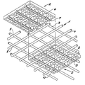
- the drawing shows a supporting frame 1 and two identical screen elements 2, one of which is shown attached to the supporting frame 1, and other is shown in a position vertically above the supporting frame 1.
- the supporting frame 1 consists of a plurality of rectilinear, mutually parallel metal bars 3, which are disposed in an upper layer, and a plurality of likewise rectilinear, parallel metal bars 4, which are disposed perpendicularly to the bars 3 of the upper layer and are attached to the underside of the upper metal bars 3, e.g. by welding, in the intersections 5 of the wires 3, 4.
- the screen elements 2, which are rectangular, are provided with through apertures 6 for the material to be treated.
- the screen elements have on their underside three guide grooves 7, which are not aligned with the areas of the apertures 6 and have such a profile that they can be snapped on to the upper layer of metal wires 3 in the supporting frame.
- the guide grooves 7 have such a depth that the lower layer of bars 4 of the supporting frame engages the underside of the screen elements 2 when the screen elements are attached to the supporting frame 1. Moreover, the metal bars 4 in the lower layer of the supporting frame 1 are disposed so that they are out of alignment with the apertures 6 of the screen elements 2.
- the sides 8 and 9 of the guide grooves 7 extend downwardly past the lowest layer of metal wires 4 and are therefore provided with recesses 10 at each intersection for the passage of the metal bars 4.
Abstract
Description
- The invention relates to a screen consisting of a supporting frame on whose upper side rectangular, mutually adjoining, apertured screen elements of resilient material are detachably attached.
- The apertured screen elements of resilient material are primarily to serve as wear-resistant screen means proper, but also have the task of protecting the supporting frame against the wear caused by the material treated by the screen.
- However, the screen elements are nevertheless worn or otherwise damaged over an extended period of time, e.g. by falling screen material, and must therefore be replaceable.
- The Norwegian Published Application NO-A-142 943 discloses a screen of the type mentioned above, in which the replaceable screen elements are attached to the supporting frame by means of stud-shaped fasteners. This technique is vitiated by the drawback that it requires the use of a very large number of fasteners, which can easily be lost and which can spring up when the frame is deflected. Moreover, the fasteners are damaged more or less when the screen elements are replaced.
- Screen have been developed in which the fasteners are integral parts of the screen elements. However, this involves a very complicated manufacturing process which adds to the manufacturing costs of the screen elements. The integral fasteners moreover break when the individual screen elements are replaced. The resulting bottom frame becomes heavy, which reduces the vibration capacity of the machine.
- DE-U-7 838 335 discloses a further development of a screen where the screen elements are attached by means of fasteners, which are firmly connected to a supporting structure. These fasteners are rectilinear, specially made metal profiles with an upwardly open U-shaped cross-section, whose free forks are extended at the top and lockingly engage longitudinal notches in the edges of their respective one of two adjoining screen elements. Thus, the screen elements are only supported at their longitudinal edges as there is no supporting frame, and the load capacity of the screen is therefore not fully satisfactory.
- Another known screen comprises a supporting frame of woven, specially made profile wires which are disposed perpendicularly to one another and to which rubber screen elements are attached, the screen elements being provided along all their edges with downwardly open grooves which can be clamped onto the wire net. The wire net cannot carry large loads without being deflected, and this construction is therefore not capable of supporting the screen elements to a satisfactory degree either. The rubber in the screen elements must moreover be so thin that it can easily be replaced, but this significantly reduces the wear resistance.
- The object of the invention is to form the screen elements so that, without the use of loose fasteners, they can be attached directly to and be firmly supported by a very rigid and pressure resistant supporting frame, which is quite conventionally attached without any intervention in the machine by way of welding, and from which the screen elements must be easy to remove or mount in case of replacement. Moreover, the screen must be easy to adapt to various mesh sizes by replacing the screen elements by others which have different aperture sizes, but fit on the same supporting frame, which can be conventionally replaced easily and rapidly by a supporting frame of a different module.
- This object is achieved according to the invention by constructing the screen defined in the foregoing so that the supporting frame consists of an upper and a lower layer of substantially rectilinear, mutually parallel metal bars or wires, the wires in the upper layer being disposed transversely to the wires in the lower layer and joined with the wires of said layer in the intersections, each screen element having at its underside at least two longitudinal guide grooves located outside the area of the apertures, said guide grooves having a profile serving to be snapped on to the upper layer of wires or bars of the supporting frame, said guide grooves having such a depth that the lower layer of wires of the supporting frame engages the underside of the screen elements. When the individual screen elements are to be replaced, they are just pulled upwards with a certain force in a direction perpendicular to the plane of the supporting frame, which cancels the clamping of a snap fastener nature between the guide grooves and the upper layer of metal bars in the supporting frame. The new screen elements are then brought into place with the guide grooves just above the upper layer of metal bars and are snapped on by being pressed downwards. The overall screen or mesh area can be increased by 20 to 30% over the previous known constructions owing to the effective support provided by the frame.
- The supporting frame may be a standard screen of the type which was previously used for screening purposes and which can be mounted on all known screening machines without changing the frame of the machine or its set-up.
- The screen elements themselves may have a mesh size from 1 mm and up to 100-120 mm without any change of the supporting frame. The supporting frame for such a screen may easily be produced even under primitive conditions merely by inverting the screen elements and then placing round bars in the guide grooves, where they may then be attached to form a net, which in turn is welded correctly together when the round bars have been removed from the screen elements.
- The manufactured screen elements are also advantageous in terms of casting. They can be made of plastics or rubber or another resilient material, which may optionally be reinforced.
- When the wires or bars in the lower layer of the supporting frame are disposed so as to be out of alignment with the apertures of the screen elements, provision is made for support in the full extent of the bars in the lower layer of the supporting frame, and these bars are covered at the same time and thus protected in their full extent by the screen elements.
- The invention will be described more fully below with reference to the drawing, which shows a perspective view of an embodiment of a screen according to the invention, seen obliquely from below.
- The drawing shows a supporting frame 1 and two
identical screen elements 2, one of which is shown attached to the supporting frame 1, and other is shown in a position vertically above the supporting frame 1. - The supporting frame 1 consists of a plurality of rectilinear, mutually parallel metal bars 3, which are disposed in an upper layer, and a plurality of likewise rectilinear, parallel metal bars 4, which are disposed perpendicularly to the bars 3 of the upper layer and are attached to the underside of the upper metal bars 3, e.g. by welding, in the intersections 5 of the wires 3, 4.
- The
screen elements 2, which are rectangular, are provided with throughapertures 6 for the material to be treated. The screen elements have on their underside three guide grooves 7, which are not aligned with the areas of theapertures 6 and have such a profile that they can be snapped on to the upper layer of metal wires 3 in the supporting frame. - The guide grooves 7 have such a depth that the lower layer of bars 4 of the supporting frame engages the underside of the
screen elements 2 when the screen elements are attached to the supporting frame 1. Moreover, the metal bars 4 in the lower layer of the supporting frame 1 are disposed so that they are out of alignment with theapertures 6 of thescreen elements 2. - In the shown embodiment the sides 8 and 9 of the guide grooves 7 extend downwardly past the lowest layer of metal wires 4 and are therefore provided with
recesses 10 at each intersection for the passage of the metal bars 4.
Claims (2)
Applications Claiming Priority (2)
| Application Number | Priority Date | Filing Date | Title |
|---|---|---|---|
| DK432980A DK145528C (en) | 1980-10-13 | 1980-10-13 | AIM |
| DK4329/80 | 1980-10-13 |
Publications (3)
| Publication Number | Publication Date |
|---|---|
| EP0062675A1 EP0062675A1 (en) | 1982-10-20 |
| EP0062675B1 true EP0062675B1 (en) | 1984-10-03 |
| EP0062675B2 EP0062675B2 (en) | 1988-03-16 |
Family
ID=8132508
Family Applications (1)
| Application Number | Title | Priority Date | Filing Date |
|---|---|---|---|
| EP81902983A Expired EP0062675B2 (en) | 1980-10-13 | 1981-10-12 | Sieve Screen |
Country Status (5)
| Country | Link |
|---|---|
| US (1) | US4486302A (en) |
| EP (1) | EP0062675B2 (en) |
| DK (1) | DK145528C (en) |
| FI (1) | FI71891C (en) |
| WO (1) | WO1982001330A1 (en) |
Cited By (1)
| Publication number | Priority date | Publication date | Assignee | Title |
|---|---|---|---|---|
| CN109351593A (en) * | 2018-09-03 | 2019-02-19 | 安徽屹翔滤材有限公司 | A kind of anti-extension hair sieve plate of sectional |
Families Citing this family (15)
| Publication number | Priority date | Publication date | Assignee | Title |
|---|---|---|---|---|
| US4634535A (en) * | 1985-03-25 | 1987-01-06 | Lott W Gerald | Drilling mud cleaning method and apparatus |
| US5248043A (en) * | 1992-02-28 | 1993-09-28 | Dorn Lloyd A | Modular retro-fit screen system for a screening deck |
| DE4300303A1 (en) * | 1993-01-08 | 1994-07-14 | Ludwig Krieger Draht Und Kunst | Strainer |
| AUPO213796A0 (en) * | 1996-09-05 | 1996-09-26 | Lettela Proprietary Limited | Modular screen panel |
| DE10053701A1 (en) | 2000-10-24 | 2002-05-08 | Oris Fahrzeugteile Riehle H | Wind stop device |
| US6926062B2 (en) | 2000-03-13 | 2005-08-09 | Oris Fahrzeugteile Hans Riehle Gmbh | Screen element for motor vehicles; in particular, wind blocker |
| DE10061562A1 (en) | 2000-12-04 | 2002-06-13 | Oris Fahrzeugteile Riehle H | windbreak |
| US20050067327A1 (en) * | 2002-01-16 | 2005-03-31 | Adams Thomas C. | Screen assemblies for shale shakers |
| WO2005051554A1 (en) * | 2003-11-25 | 2005-06-09 | Weatherford Australia Pty Limited | A screening module |
| US7753213B2 (en) * | 2006-03-30 | 2010-07-13 | M-I Llc | Composite screen |
| US7810648B2 (en) * | 2006-06-21 | 2010-10-12 | Tylinter, Inc. | Screen assembly for separating material according to particle size |
| SE531876C2 (en) * | 2007-12-19 | 2009-09-01 | Sandvik Intellectual Property | A vibration screen with a wear protection |
| AU2008201346B2 (en) * | 2008-02-15 | 2012-10-18 | Screenex Manufacturing (Pty) Ltd | Screen panels |
| ZA201006277B (en) * | 2009-08-28 | 2012-01-25 | Allan Maskew (Pty) Ltd | A mine screen |
| BR112017014357B1 (en) * | 2014-12-31 | 2021-07-06 | Fp Canmechanica Inc | SCREEN ASSEMBLY FOR A VIBRATORY SCREENING MACHINE |
Family Cites Families (5)
| Publication number | Priority date | Publication date | Assignee | Title |
|---|---|---|---|---|
| DE1758860A1 (en) * | 1968-08-22 | 1971-06-03 | Stahlgruber Gruber & Co Otto | Elastic sieve bottom |
| DE2632511C3 (en) * | 1976-07-20 | 1983-12-15 | Steinhaus GmbH, 4330 Mülheim | Siebfeld |
| DE2622709C3 (en) * | 1976-05-21 | 1983-02-24 | Steinhaus GmbH, 4330 Mülheim | Siebfeld |
| DE2754044B1 (en) * | 1977-12-05 | 1979-04-19 | Willi-Klaus Kinker | Industrial sieve bottom for processing bulk goods |
| DE2849838B1 (en) * | 1978-11-17 | 1979-09-13 | Hein Lehmann Ag | Sieve bottom |
-
1980
- 1980-10-13 DK DK432980A patent/DK145528C/en not_active IP Right Cessation
-
1981
- 1981-10-12 EP EP81902983A patent/EP0062675B2/en not_active Expired
- 1981-10-12 US US06/395,000 patent/US4486302A/en not_active Expired - Lifetime
- 1981-10-12 WO PCT/DK1981/000088 patent/WO1982001330A1/en active IP Right Grant
-
1982
- 1982-06-10 FI FI822073A patent/FI71891C/en not_active IP Right Cessation
Cited By (1)
| Publication number | Priority date | Publication date | Assignee | Title |
|---|---|---|---|---|
| CN109351593A (en) * | 2018-09-03 | 2019-02-19 | 安徽屹翔滤材有限公司 | A kind of anti-extension hair sieve plate of sectional |
Also Published As
| Publication number | Publication date |
|---|---|
| US4486302A (en) | 1984-12-04 |
| EP0062675A1 (en) | 1982-10-20 |
| EP0062675B2 (en) | 1988-03-16 |
| FI822073A0 (en) | 1982-06-10 |
| DK145528B (en) | 1982-12-06 |
| DK145528C (en) | 1983-05-02 |
| WO1982001330A1 (en) | 1982-04-29 |
| FI71891C (en) | 1987-03-09 |
| DK432980A (en) | 1982-04-14 |
| FI71891B (en) | 1986-11-28 |
Similar Documents
| Publication | Publication Date | Title |
|---|---|---|
| EP0062675B1 (en) | Sieve screen | |
| US4380494A (en) | Vibrating screen with self-supporting screen cloth | |
| US4265742A (en) | Screen element | |
| EP1002588B1 (en) | Panel for a screen | |
| US4563270A (en) | Self cleaning, perforated plate for oscillating sieve | |
| EP1333904B1 (en) | A screen for a shale shaker | |
| US6253926B1 (en) | Modular screen panel | |
| US4670136A (en) | Screen surfacing with exchangeable screen elements | |
| US4347129A (en) | Screening module | |
| CA2137751A1 (en) | Screening panel attachment system | |
| EP0891819A3 (en) | Improved screening apparatus | |
| GB2074902A (en) | Vibrating screen with unclogging unit | |
| US3970550A (en) | Moulded elastomeric screen mat for sieving devices | |
| US3134733A (en) | Screens | |
| EP0032436B1 (en) | Screening apparatus | |
| WO2001000332A1 (en) | A screen, a panel for a screen, a shale shaker and a method of screening | |
| US4278535A (en) | Screen decks | |
| CA2623992C (en) | Screen panels | |
| GB2092917A (en) | Screens | |
| CA1202602A (en) | Screening system | |
| CA1184538A (en) | Screen | |
| EP0958067A1 (en) | Screen with overlapping elongate screen cloth elements | |
| GB2073618A (en) | Vibratory screening panels | |
| GB2067100A (en) | Screening apparatus | |
| JPH02139073A (en) | Sieve of vibration screening apparatus |
Legal Events
| Date | Code | Title | Description |
|---|---|---|---|
| PUAI | Public reference made under article 153(3) epc to a published international application that has entered the european phase |
Free format text: ORIGINAL CODE: 0009012 |
|
| 17P | Request for examination filed |
Effective date: 19820611 |
|
| AK | Designated contracting states |
Designated state(s): DE FR GB NL SE |
|
| GRAA | (expected) grant |
Free format text: ORIGINAL CODE: 0009210 |
|
| AK | Designated contracting states |
Designated state(s): DE FR GB NL SE |
|
| REF | Corresponds to: |
Ref document number: 3166504 Country of ref document: DE Date of ref document: 19841108 |
|
| ET | Fr: translation filed | ||
| PLBI | Opposition filed |
Free format text: ORIGINAL CODE: 0009260 |
|
| 26 | Opposition filed |
Opponent name: STEINHAUS GMBH Effective date: 19850621 |
|
| NLR1 | Nl: opposition has been filed with the epo |
Opponent name: STEINHAUS GMBH |
|
| RAP2 | Party data changed (patent owner data changed or rights of a patent transferred) |
Owner name: AKTIESELSKABET NORDISKE KABEL-OG TRAADFABRIKER |
|
| NLT2 | Nl: modifications (of names), taken from the european patent patent bulletin |
Owner name: AKTIESELSKABET NORDISKE KABEL-OG TRAADFABRIKER TE |
|
| PUAH | Patent maintained in amended form |
Free format text: ORIGINAL CODE: 0009272 |
|
| STAA | Information on the status of an ep patent application or granted ep patent |
Free format text: STATUS: PATENT MAINTAINED AS AMENDED |
|
| 27A | Patent maintained in amended form |
Effective date: 19880316 |
|
| AK | Designated contracting states |
Kind code of ref document: B2 Designated state(s): DE FR GB NL SE |
|
| ET3 | Fr: translation filed ** decision concerning opposition | ||
| NLR2 | Nl: decision of opposition | ||
| NLR3 | Nl: receipt of modified translations in the netherlands language after an opposition procedure | ||
| EAL | Se: european patent in force in sweden |
Ref document number: 81902983.6 |
|
| PGFP | Annual fee paid to national office [announced via postgrant information from national office to epo] |
Ref country code: GB Payment date: 19991006 Year of fee payment: 19 |
|
| PGFP | Annual fee paid to national office [announced via postgrant information from national office to epo] |
Ref country code: DE Payment date: 20001002 Year of fee payment: 20 |
|
| PGFP | Annual fee paid to national office [announced via postgrant information from national office to epo] |
Ref country code: SE Payment date: 20001009 Year of fee payment: 20 |
|
| PGFP | Annual fee paid to national office [announced via postgrant information from national office to epo] |
Ref country code: FR Payment date: 20001010 Year of fee payment: 20 |
|
| PG25 | Lapsed in a contracting state [announced via postgrant information from national office to epo] |
Ref country code: GB Free format text: LAPSE BECAUSE OF NON-PAYMENT OF DUE FEES Effective date: 20001012 |
|
| PGFP | Annual fee paid to national office [announced via postgrant information from national office to epo] |
Ref country code: NL Payment date: 20001026 Year of fee payment: 20 |
|
| GBPC | Gb: european patent ceased through non-payment of renewal fee |
Effective date: 20001012 |
|
| PG25 | Lapsed in a contracting state [announced via postgrant information from national office to epo] |
Ref country code: NL Free format text: LAPSE BECAUSE OF EXPIRATION OF PROTECTION Effective date: 20011012 |
|
| PG25 | Lapsed in a contracting state [announced via postgrant information from national office to epo] |
Ref country code: SE Free format text: THE PATENT HAS BEEN ANNULLED BY A DECISION OF A NATIONAL AUTHORITY Effective date: 20011030 |
|
| EUG | Se: european patent has lapsed |
Ref document number: 81902983.6 |
|
| NLV7 | Nl: ceased due to reaching the maximum lifetime of a patent |
Effective date: 20011012 |