EP0062538B1 - Apparatus for locating faults in electric cables - Google Patents
Apparatus for locating faults in electric cables Download PDFInfo
- Publication number
- EP0062538B1 EP0062538B1 EP82301823A EP82301823A EP0062538B1 EP 0062538 B1 EP0062538 B1 EP 0062538B1 EP 82301823 A EP82301823 A EP 82301823A EP 82301823 A EP82301823 A EP 82301823A EP 0062538 B1 EP0062538 B1 EP 0062538B1
- Authority
- EP
- European Patent Office
- Prior art keywords
- fault
- cable
- pulses
- waveforms
- recording
- Prior art date
- Legal status (The legal status is an assumption and is not a legal conclusion. Google has not performed a legal analysis and makes no representation as to the accuracy of the status listed.)
- Expired
Links
- 230000015654 memory Effects 0.000 claims abstract description 18
- 238000000034 method Methods 0.000 claims abstract description 13
- 238000009434 installation Methods 0.000 claims abstract description 11
- 230000004044 response Effects 0.000 description 3
- 230000001052 transient effect Effects 0.000 description 3
- 239000003990 capacitor Substances 0.000 description 2
- 230000001143 conditioned effect Effects 0.000 description 2
- 238000010586 diagram Methods 0.000 description 2
- 238000005259 measurement Methods 0.000 description 2
- 238000005070 sampling Methods 0.000 description 2
- 230000000903 blocking effect Effects 0.000 description 1
- 230000015556 catabolic process Effects 0.000 description 1
- 238000012790 confirmation Methods 0.000 description 1
- 238000001514 detection method Methods 0.000 description 1
- 230000001747 exhibiting effect Effects 0.000 description 1
- 230000006870 function Effects 0.000 description 1
- 231100001261 hazardous Toxicity 0.000 description 1
- 238000000926 separation method Methods 0.000 description 1
Images

Classifications
-
- G—PHYSICS
- G01—MEASURING; TESTING
- G01R—MEASURING ELECTRIC VARIABLES; MEASURING MAGNETIC VARIABLES
- G01R31/00—Arrangements for testing electric properties; Arrangements for locating electric faults; Arrangements for electrical testing characterised by what is being tested not provided for elsewhere
- G01R31/08—Locating faults in cables, transmission lines, or networks
- G01R31/11—Locating faults in cables, transmission lines, or networks using pulse reflection methods
Definitions
- This invention relates to apparatus for locating faults in electric cables using pulse-echo or impulse current techniques, and is applicable more especially, but not exclusively, to fault detection apparatus for use in power distribution cable installations having a number of single or three- phase branches, especially those with difficult or impossible access to a termination or terminations, such as low voltage distribution systems.
- Pulse-echo techniques have been used for some time for detecting faults in high voltage cables for example, as disclosed in our EP-A-0 006 005.
- This publication discloses apparatus for detecting and locating a fault in an electric cable or cable installation using a pulse-echo technique comprising means for injecting step function or single pulses into the cable or cable installation, means for digitising and storing the pulse-echo signal obtained under two different conditions of the cable and means for retrieving the signals obtained under the two said conditions, comparing them and thus locating the position of the fault. Whilst this apparatus has been found to work, there is a risk that a transient fault may be missed. This known technique can more easily detect faults when the fault resistance is not greater than the cable impedance.
- fault-burning a technique known as "fault-burning" can be used (in which an abnormally high voltage is applied to the cable) to accentuate the fault and reduce its resistance.
- the impulse current. method of fault location (as described in our UK Patent Nos. 1508351 and 1508352) can be applied, whereby the fault is broken down for a short period of time using a high voltage impulse and the resulting transient waveforms are captured by a digital signal acquisition system.
- fault burning nor the impulse current method can however, be used on low voltage cables due to the difficulty of disconnecting all the consumer's apparatus normally supplied by the faulty cable.
- US-A-4 151 459 describes a method of and apparatus for localising line faults in security lines for ski-lifts and the like in which a voltage step is applied to the security line, the response to the voltage step is determined and this response is compared to the response obtained in the ab- sense of a fault, the difference resulting from the comparison indicating the place of the fault and type of fault.
- This apparatus solves a totally different problem to that encountered in detecting and locating faults in electric cables or cable installations. This apparatus can only be used to locate faults in a.single, dead cable, and can only locate stable and permanent faults.
- An object of the present invention is to provide improved apparatus that can be used with the consumer's apparatus still connected, since its use does not entail hazardous high voltages as the cable is only re-energised with the normal system voltage.
- a further object is to provide improved apparatus that will detect low voltage cable faults exhibiting a non-linear and unstable voltage: current characteristic where the fault current only flows during the times when the instantaneous voltage of the supply is greater than the arc voltage of the fault.
- a still further object is to provide apparatus which considerably reduces the risk of missing a transient fault and provides a more accurate determination of the position of the fault.
- the improved apparatus of this invention can be used for high and low voltage cables.
- the improved apparatus for detecting and locating a fault in an electric cable or cable installation using a pulse-echo technique or impulse current technique comprises a low voltage pulse generator; an analogue-to-digital converter for digitising the pulse echo waveforms of a predetermined number of pulses obtained under fault-present and fault-free conditions of the cable; a digital store and memory for recording and storing the waveforms; means for terminating the recording of waveforms of pulses a predetermined time after a fault condition is actuated; and means for retrieving the waveforms obtained under the two separate conditions, comparing them and thus locating the position of the fault.
- the arrangement is such that the memory is instructed to stop recording when a fault condition is detected, the memory retaining recordings of the waveforms of a number of pulses before . the fault is detected, and recordings of the waveforms of the pulses after the fault is detected, before the recording of the waveforms of the pulses is terminated. Waveforms obtained under normal and fault conditions are stored and, by retrieving and comparing them, the location of the fault is determined.
- the memory is continually refreshed with the waveform of each new pulse replacing the recording of the waveform of the earliest of the stored pulses.
- the improved apparatus also comprises means for recording a power frequency waveform (usually 50 or 60 cycles per second) simultaneously with the waveforms of the pulses, preferably at a sampling rate of 80 microseconds.
- a power frequency waveform usually 50 or 60 cycles per second
- This slower sampling rate of the voltage waveform gives easier recognition of the fault condition and selection of appropriate blocks of high speed memory for comparison, allowing the position of the fault to be accurately determined.
- the time interval between the pulses is typically 1 millisecond. If the time interval is too long, the fault may be missed; if the time interval is too short, the signal becomes very complex.
- the predetermined time allows eight pulses to be injected after a fault condition is detected, and preferably the memory records the waveforms of sixteen consecutive pulses at any one time.
- the memory contains recordings of the waveforms of eight pulses before the fault is detected and eight after.
- Examples of two different conditions of a cable for which pulse-echo or impulse-current waveforms can be obtained, digitised and stored include (a) before the fault appears and after the fault appears and (b) before the fault is conditioned (e.g. by fault burning or re-energisation) and after the fault is conditioned.
- the improved apparatus in accordance with the invention preferably includes a triggering circuit which is responsive to the level of current flowing in the cable.
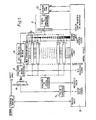
- high speed memories 19 are clocked at 20 MHz.
- the memories 19 are organised as 256 byte blocks which are enabled sequentially every 1 mS for 12.8 microseconds; 0.5 microseconds after enabling each block a low voltage pulse generator 15 injects a signal into the cable under test via a blocking capacitor 16.
- the resulting pulse echo or impulse current waveform is stored in the enabled memory of high speed memories 19. The process is repeated every 1 mS, the memories 19 being sequentially enabled.
- a control circuit 20 allows eight more pulses to be transmitted before switching the memories 1.9 over to "read".
- any two of the high speed memories 19 can be displayed simultaneously on a cathode ray tube 22 for comparison (see Figure 4), and a signal is applied to the Z axis of the tube to allow accurate measurement of the time interval between the injected pulse and the point of separation of the two waveforms, from which measurement the position of the fault can be determined.
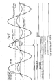
- a shift register 18 is used to store the power frequency waveform before, during and after the fault.
- the shift register 18 is clocked every 80 microseconds which, if it is 256 words long, gives a total recording time of 20 mS.
- the shift register 18 (which includes internal re-circulation) can be displayed on the cathode ray tube 22 (see Figure 3) and the "points on wave" where the high speed memories 19 were enabled are identified by intensifying the displayed trace during the appropriate clock pulses.
- Resutts obtained on a multibranched network will often be ambiguous as several positions on a cable may be equidistant from the measuring point.
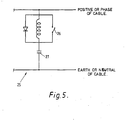
- the problem is resolved using the artificial "fault" circuit 25 illustrated in Figure 5 which can be connected to either energised or unenergised cables to provide a reference waveform or waveforms.
- the switch 26 With the switch 26 closed the capacitor 27 appears as a permanent short-circuit fault. With the switch 26 open the circuit 25 can be used on energised cables to exhibit a characteristic which varies during a cycle of the supply voltage.
- the circuit 25 During the time from negative peak voltage to positive peak voltage the circuit 25 appears as a short-circuit to the high frequency pulses; during the remainder of the cycle the circuit presents a high impedance - that is, the short circuit disappears. Using the circuit 25 the position of the fault can be more accurately determined.
Landscapes
- Physics & Mathematics (AREA)
- General Physics & Mathematics (AREA)
- Locating Faults (AREA)
- Insulated Conductors (AREA)
- Monitoring And Testing Of Transmission In General (AREA)
- Testing Of Short-Circuits, Discontinuities, Leakage, Or Incorrect Line Connections (AREA)
- Electric Cable Installation (AREA)
Priority Applications (1)
| Application Number | Priority Date | Filing Date | Title |
|---|---|---|---|
| AT82301823T ATE24359T1 (de) | 1981-04-07 | 1982-04-06 | Vorrichtung zum lokalisieren von fehlern in elektrischen kabeln. |
Applications Claiming Priority (2)
| Application Number | Priority Date | Filing Date | Title |
|---|---|---|---|
| GB8110868 | 1981-04-07 | ||
| GB8110868 | 1981-04-07 |
Publications (2)
| Publication Number | Publication Date |
|---|---|
| EP0062538A1 EP0062538A1 (en) | 1982-10-13 |
| EP0062538B1 true EP0062538B1 (en) | 1986-12-17 |
Family
ID=10520994
Family Applications (1)
| Application Number | Title | Priority Date | Filing Date |
|---|---|---|---|
| EP82301823A Expired EP0062538B1 (en) | 1981-04-07 | 1982-04-06 | Apparatus for locating faults in electric cables |
Country Status (9)
| Country | Link |
|---|---|
| US (1) | US4491782A (show.php) |
| EP (1) | EP0062538B1 (show.php) |
| JP (1) | JPS57179672A (show.php) |
| AT (1) | ATE24359T1 (show.php) |
| AU (1) | AU550374B2 (show.php) |
| DE (1) | DE3274765D1 (show.php) |
| GB (1) | GB2096856B (show.php) |
| IN (1) | IN158099B (show.php) |
| ZA (1) | ZA822363B (show.php) |
Families Citing this family (33)
| Publication number | Priority date | Publication date | Assignee | Title |
|---|---|---|---|---|
| US4914394A (en) * | 1986-07-31 | 1990-04-03 | Electromagnetic Techology, Inc. | Pocket-size time domain reflectometer |
| US4797621A (en) * | 1987-07-08 | 1989-01-10 | Midwesco, Inc. | Leak detector and locator utilizing time domain reflectometry and sampling techniques |
| US4887041A (en) * | 1988-02-17 | 1989-12-12 | University Of Connecticut | Method and instrumentation for the detection, location and characterization of partial discharges and faults in electric power cables |
| EP0391312A3 (en) * | 1989-04-03 | 1992-03-18 | International Business Machines Corporation | System for and method of determining cable characteristics |
| DE3919497C2 (de) * | 1989-06-15 | 1998-05-14 | Hagenuk Kmt Kabelmestechnik Gm | Verfahren und Vorrichtung zur Ortung nicht festbrennbarer Kabelfehler |
| US5083086A (en) * | 1990-07-12 | 1992-01-21 | James G. Biddle Co. | Differential arc reflectometry |
| JPH04285874A (ja) * | 1991-03-13 | 1992-10-09 | Chubu Electric Power Co Inc | ケーブルの事故点標定方法 |
| US5134377A (en) * | 1991-06-04 | 1992-07-28 | W. L. Gore & Associates, Inc. | TDR system and method for detecting leakage of a liquid |
| US5457990A (en) * | 1991-12-03 | 1995-10-17 | Cambridge Consultants Limited | Method and apparatus for determining a fluid level in the vicinity of a transmission line |
| US5272439A (en) * | 1992-02-21 | 1993-12-21 | University Of Connecticut | Method and apparatus for the detection and location of faults and partial discharges in shielded cables |
| DE4220410C1 (de) * | 1992-06-19 | 1993-11-25 | Siemens Ag | Verfahren zum Bestimmen eines Fehlers auf einer elektrischen Übertragungsleitung |
| DE4323780A1 (de) * | 1992-08-10 | 1994-02-17 | Midwesco Inc | Leckerfassungs- und Ortungseinrichtung unter Verwendung eines adaptiven Bezugsschwellenwerts und analogen Vergleichs |
| CN1036419C (zh) * | 1992-11-19 | 1997-11-12 | 淄博科汇电气有限公司 | 一种电力电缆故障自动测距方法及装置 |
| US5321365A (en) * | 1993-03-03 | 1994-06-14 | Tektronix, Inc. | Reduced noise sensitivity in inverse scattering through filtering |
| GB9322920D0 (en) * | 1993-11-06 | 1993-12-22 | Bicc Plc | Device for testing an electrical line |
| US5608328A (en) * | 1994-11-18 | 1997-03-04 | Radar Engineers | Method and apparatus for pin-pointing faults in electric power lines |
| US5650728A (en) * | 1995-04-03 | 1997-07-22 | Hubbell Incorporated | Fault detection system including a capacitor for generating a pulse and a processor for determining admittance versus frequency of a reflected pulse |
| DE19726538C1 (de) | 1997-06-23 | 1998-10-01 | Daimler Benz Ag | Verfahren und Schaltungsanordnung zur Überprüfung von Leitungsfehlern in einem Zweidraht-Bus-System |
| DE19726539C2 (de) * | 1997-06-23 | 2001-09-27 | Daimler Chrysler Ag | Verfahren und Schaltungsanordnung zur Lokalisierung eines Kurzschluß oder Kabelbruchs in einem Bus-System |
| US6285195B1 (en) * | 1998-03-16 | 2001-09-04 | David Needle | Time domain reflectometry apparatus and method |
| DE19852591A1 (de) * | 1998-11-14 | 2000-05-25 | Daimler Chrysler Ag | Verfahren zur Prüfung einer Erdverbindung |
| US6161077A (en) * | 1999-01-05 | 2000-12-12 | Hubbell Incorporated | Partial discharge site location system for determining the position of faults in a high voltage cable |
| USD448239S1 (en) | 2000-04-28 | 2001-09-25 | Cherry Terrace Inc. | Kettle's body |
| US6448781B1 (en) * | 2000-10-06 | 2002-09-10 | Northrop Grumman Corporation | Method and system for analyzing cable faults |
| GB0027235D0 (en) * | 2000-11-07 | 2000-12-27 | Smiths Industries Plc | Arc location |
| GB0106141D0 (en) | 2001-03-13 | 2001-05-02 | Thames Water Utilities | Sealing methods |
| TW567321B (en) | 2002-07-02 | 2003-12-21 | Via Tech Inc | Method of using waveform to judge position of connection failure |
| US6822457B2 (en) * | 2003-03-27 | 2004-11-23 | Marshall B. Borchert | Method of precisely determining the location of a fault on an electrical transmission system |
| ATE507180T1 (de) * | 2004-03-16 | 2011-05-15 | Otis Elevator Co | Strategien zur zuführung von elektrischen signalen zur überwachung eines zustands eines aufzugslasttragglieds |
| US9275543B2 (en) * | 2012-04-26 | 2016-03-01 | Chris Oswalt | Tamper detection for pulse-producing device |
| US9429613B1 (en) | 2012-07-02 | 2016-08-30 | Marshall B. Borchert | Time domain reflectometer |
| US9550422B2 (en) | 2014-01-16 | 2017-01-24 | Ford Global Technologies, Llc | Vehicle high voltage interlock startup |
| CN114441606B (zh) * | 2021-12-28 | 2023-11-24 | 国网河北省电力有限公司电力科学研究院 | 电缆水树枝老化缺陷的定位方法及其测试方法、设备 |
Family Cites Families (8)
| Publication number | Priority date | Publication date | Assignee | Title |
|---|---|---|---|---|
| US2628267A (en) * | 1949-03-31 | 1953-02-10 | Theodore W Stringfield | Electric line fault locators |
| DE1219585B (de) * | 1961-12-20 | 1966-06-23 | Siemens Ag | Anordnung zum Ermitteln von Fehler- oder Inhomogenitaetsstellen elektrischer Leitungen |
| GB1352124A (en) * | 1970-07-08 | 1974-05-08 | Electricity Council | Cable fault location |
| FR2319135A1 (fr) * | 1975-07-22 | 1977-02-18 | Metraplan Spa | Procede et dispositif destine a la localisation des defauts des lignes de securite pour remontees mecaniques |
| FR2334116A2 (fr) * | 1975-12-03 | 1977-07-01 | Metraplan Spa | Procede et dispositif destine a la localisation des defauts des lignes de securite pour remontees mecaniques |
| DE2953266A1 (de) * | 1978-05-31 | 1980-11-27 | Bicc Ltd | Verfahren und vorrichtung zum ermitteln und lokalisieren von fehlern in elektrischen kabeln |
| FR2454626A1 (fr) * | 1979-04-17 | 1980-11-14 | Electricite De France | Enregistreur de signaux sur perturbation |
| CH649847A5 (en) * | 1979-05-04 | 1985-06-14 | Bbc Brown Boveri & Cie | Method for fault location in an electrical line |
-
1982
- 1982-04-02 IN IN272/DEL/82A patent/IN158099B/en unknown
- 1982-04-02 US US06/365,044 patent/US4491782A/en not_active Expired - Fee Related
- 1982-04-05 ZA ZA822363A patent/ZA822363B/xx unknown
- 1982-04-05 AU AU82358/82A patent/AU550374B2/en not_active Ceased
- 1982-04-06 EP EP82301823A patent/EP0062538B1/en not_active Expired
- 1982-04-06 DE DE8282301823T patent/DE3274765D1/de not_active Expired
- 1982-04-06 AT AT82301823T patent/ATE24359T1/de not_active IP Right Cessation
- 1982-04-06 GB GB8210188A patent/GB2096856B/en not_active Expired
- 1982-04-07 JP JP5679582A patent/JPS57179672A/ja active Pending
Also Published As
| Publication number | Publication date |
|---|---|
| GB2096856B (en) | 1985-07-24 |
| JPS57179672A (en) | 1982-11-05 |
| GB2096856A (en) | 1982-10-20 |
| ATE24359T1 (de) | 1987-01-15 |
| DE3274765D1 (en) | 1987-01-29 |
| IN158099B (show.php) | 1986-08-30 |
| EP0062538A1 (en) | 1982-10-13 |
| ZA822363B (en) | 1983-02-23 |
| US4491782A (en) | 1985-01-01 |
| AU8235882A (en) | 1982-10-14 |
| AU550374B2 (en) | 1986-03-20 |
Similar Documents
| Publication | Publication Date | Title |
|---|---|---|
| EP0062538B1 (en) | Apparatus for locating faults in electric cables | |
| US4475079A (en) | Apparatus for locating faults in electric cables | |
| Gale et al. | Fault location based on travelling waves | |
| US5475312A (en) | Method and device for distinguishing between partial discharge and electrical noise | |
| US4110684A (en) | Method of detecting faults on low voltage distribution electric cables utilizing a plurality of transient recorders | |
| US6161077A (en) | Partial discharge site location system for determining the position of faults in a high voltage cable | |
| US4165482A (en) | Cable fault location | |
| US6385561B1 (en) | Automatic fault location in cabling systems | |
| EP1090302B1 (en) | System measuring partial discharge using digital peak detection | |
| EP1086380B1 (en) | System for concurrent digital measurement of peak voltage and rms voltage in high voltage system | |
| EP3736584B1 (en) | Systems and methods for arc fault detection built-in-test | |
| EP1086381A1 (en) | System for digital measurement of breakdown voltage of high-voltage samples | |
| US4459545A (en) | Apparatus for detecting a current peak value and a voltage peak value | |
| US3665294A (en) | System for determining the ignition advance in the distribution of an engine | |
| Livie et al. | The application of on-line travelling wave techniques in the location of intermittent faults on low voltage underground cables | |
| JPH055064B2 (show.php) | ||
| SU1762279A1 (ru) | Устройство дл определени рассто ни до места повреждени кабельных линий электропередач | |
| SU1046695A2 (ru) | Устройство дл измерени амплитуды импульсного напр жени | |
| Carminati et al. | A fast hybrid system for PD measurement | |
| SU754332A1 (ru) | Устройство для определения расстояния до места повреждения в линии электропередачи1 | |
| WO1996006362A1 (en) | Cable fault location | |
| Gale | Monitoring protection and switchgear performance on distribution systems | |
| JPH02271267A (ja) | 過電圧測定装置 | |
| Wayne | On-line tensile test data reduction using a remote analog computer | |
| JPH01176950A (ja) | 電力用開閉機器の動作時間計測装置 |
Legal Events
| Date | Code | Title | Description |
|---|---|---|---|
| PUAI | Public reference made under article 153(3) epc to a published international application that has entered the european phase |
Free format text: ORIGINAL CODE: 0009012 |
|
| AK | Designated contracting states |
Designated state(s): AT BE CH DE FR IT LI LU NL SE |
|
| 17P | Request for examination filed |
Effective date: 19830118 |
|
| RAP1 | Party data changed (applicant data changed or rights of an application transferred) |
Owner name: BICC PUBLIC LIMITED COMPANY |
|
| GRAA | (expected) grant |
Free format text: ORIGINAL CODE: 0009210 |
|
| AK | Designated contracting states |
Kind code of ref document: B1 Designated state(s): AT BE CH DE FR IT LI LU NL SE |
|
| REF | Corresponds to: |
Ref document number: 24359 Country of ref document: AT Date of ref document: 19870115 Kind code of ref document: T |
|
| REF | Corresponds to: |
Ref document number: 3274765 Country of ref document: DE Date of ref document: 19870129 |
|
| ITF | It: translation for a ep patent filed | ||
| ET | Fr: translation filed | ||
| PG25 | Lapsed in a contracting state [announced via postgrant information from national office to epo] |
Ref country code: LU Free format text: LAPSE BECAUSE OF NON-PAYMENT OF DUE FEES Effective date: 19870430 |
|
| PLBE | No opposition filed within time limit |
Free format text: ORIGINAL CODE: 0009261 |
|
| STAA | Information on the status of an ep patent application or granted ep patent |
Free format text: STATUS: NO OPPOSITION FILED WITHIN TIME LIMIT |
|
| 26N | No opposition filed | ||
| PGFP | Annual fee paid to national office [announced via postgrant information from national office to epo] |
Ref country code: FR Payment date: 19890308 Year of fee payment: 8 Ref country code: AT Payment date: 19890308 Year of fee payment: 8 |
|
| PGFP | Annual fee paid to national office [announced via postgrant information from national office to epo] |
Ref country code: CH Payment date: 19890313 Year of fee payment: 8 |
|
| PGFP | Annual fee paid to national office [announced via postgrant information from national office to epo] |
Ref country code: SE Payment date: 19890315 Year of fee payment: 8 |
|
| PGFP | Annual fee paid to national office [announced via postgrant information from national office to epo] |
Ref country code: BE Payment date: 19890328 Year of fee payment: 8 |
|
| PGFP | Annual fee paid to national office [announced via postgrant information from national office to epo] |
Ref country code: DE Payment date: 19890331 Year of fee payment: 8 |
|
| PGFP | Annual fee paid to national office [announced via postgrant information from national office to epo] |
Ref country code: LU Payment date: 19890403 Year of fee payment: 8 |
|
| ITTA | It: last paid annual fee | ||
| PGFP | Annual fee paid to national office [announced via postgrant information from national office to epo] |
Ref country code: NL Payment date: 19890430 Year of fee payment: 8 |
|
| PG25 | Lapsed in a contracting state [announced via postgrant information from national office to epo] |
Ref country code: AT Effective date: 19900406 |
|
| PG25 | Lapsed in a contracting state [announced via postgrant information from national office to epo] |
Ref country code: SE Effective date: 19900407 |
|
| PG25 | Lapsed in a contracting state [announced via postgrant information from national office to epo] |
Ref country code: LI Effective date: 19900430 Ref country code: CH Effective date: 19900430 Ref country code: BE Effective date: 19900430 |
|
| BERE | Be: lapsed |
Owner name: BICC PUBLIC LTD CY Effective date: 19900430 |
|
| PG25 | Lapsed in a contracting state [announced via postgrant information from national office to epo] |
Ref country code: NL Effective date: 19901101 |
|
| NLV4 | Nl: lapsed or anulled due to non-payment of the annual fee | ||
| PG25 | Lapsed in a contracting state [announced via postgrant information from national office to epo] |
Ref country code: FR Effective date: 19901228 |
|
| REG | Reference to a national code |
Ref country code: CH Ref legal event code: PL |
|
| PG25 | Lapsed in a contracting state [announced via postgrant information from national office to epo] |
Ref country code: DE Effective date: 19910101 |
|
| REG | Reference to a national code |
Ref country code: FR Ref legal event code: ST |
|
| EUG | Se: european patent has lapsed |
Ref document number: 82301823.9 Effective date: 19910115 |