EP0062069A1 - Device for operating hand of industrial robot - Google Patents
Device for operating hand of industrial robot Download PDFInfo
- Publication number
- EP0062069A1 EP0062069A1 EP81902756A EP81902756A EP0062069A1 EP 0062069 A1 EP0062069 A1 EP 0062069A1 EP 81902756 A EP81902756 A EP 81902756A EP 81902756 A EP81902756 A EP 81902756A EP 0062069 A1 EP0062069 A1 EP 0062069A1
- Authority
- EP
- European Patent Office
- Prior art keywords
- hand
- air
- industrial robot
- driving
- solenoid valve
- Prior art date
- Legal status (The legal status is an assumption and is not a legal conclusion. Google has not performed a legal analysis and makes no representation as to the accuracy of the status listed.)
- Withdrawn
Links
Images
Classifications
-
- B—PERFORMING OPERATIONS; TRANSPORTING
- B25—HAND TOOLS; PORTABLE POWER-DRIVEN TOOLS; MANIPULATORS
- B25J—MANIPULATORS; CHAMBERS PROVIDED WITH MANIPULATION DEVICES
- B25J3/00—Manipulators of master-slave type, i.e. both controlling unit and controlled unit perform corresponding spatial movements
- B25J3/04—Manipulators of master-slave type, i.e. both controlling unit and controlled unit perform corresponding spatial movements involving servo mechanisms
-
- B—PERFORMING OPERATIONS; TRANSPORTING
- B25—HAND TOOLS; PORTABLE POWER-DRIVEN TOOLS; MANIPULATORS
- B25J—MANIPULATORS; CHAMBERS PROVIDED WITH MANIPULATION DEVICES
- B25J13/00—Controls for manipulators
- B25J13/08—Controls for manipulators by means of sensing devices, e.g. viewing or touching devices
- B25J13/081—Touching devices, e.g. pressure-sensitive
- B25J13/082—Grasping-force detectors
Definitions
- the present invention relates to a device for operating a hand of an industrial robot. More particularly, it relates to a device for operating a hand of an industrial robot whose grasping force can be controlled stepwisely.
- an air cylinder is driven by a fixed pneumatic pressure so as to generate the grasping force of the hand.
- a finger-driving mechanism 1 is so constructed as to open or close the finger portions 11 and 12 in accordance with the movement of the piston 31 of the air cylinder 3. Accordingly, the force with which the finger portions 11 and 12 grasp an article to be gripped 2 is determined by the thrust F of the air cylinder 3.
- This thrust F is given by the following expression:
- S donotes the pressure-receiving area of the piston
- P the pneumatic pressure in the cylinder
- n the efficiency
- the thrust F is uniquely determined by the feed pressure of the air so that the grasping force of the hand becomes constant. Therefore, in the device for operating the hand of the industrial robot as shown in Fig. 1, the article to be gripped 2 is gripped with a constant grasping force which is determined by the feed pressure of the air P. This leads to a problem in which the grasping force cannot be switched in accordance with the state of the article to be gripped, and in some cases the article to be gripped is broken.
- the principal object of the present invention is to provide a device for operating a hand of an industrial robot in which the grasping force can be controlled in accordance with the state of the object to be gripped, in view of the. problem of the prior art described above and on the basis of the concept of a passage which includes a pressure-reducing valve and which branches from a fluid supply passage for a fluid pressure cylinder so as to switch fluid feed by a solenoid valve.
- a device for operating a hand of an industrial robot comprising fluid pressure cylinders as a driving mechanism of the hand of the industrial robot, branch passages including pressure-reducing valves being provided in a fluid supply passage to said fluid pressure cylinder, the supply of fluid being switched by solenoid valves, the switching of said solenoid valves being carried out in accordance with the grasping force which has been selected in a teaching mode of said industrial robot, whereby the grasping force of said hand is adapted so that it can be controlled stepwisely.
- FIG. 2 A device for operating a hand of an industrial robot in accordance with an embodiment of the present invention is illustrated in Figs. 2, 3 and 4.
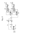
- FIG. 2 the control flow of a hand 4 according to the present invention is illustrated.
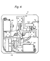
- An external view of the hand 4 is illustrated in Fig. 3, and the interior mechanism of the hand 4 is shown in Fig. 4.
- the hand 4 has two sets of finger mechanisms 41 and 42 which are, respectively, driven forward and backward and rightward and leftward.
- the finger mechanisms 41 and 42 are, respectively, driven by air cylinders 43 and 44. When the piston of the air cylinder 43 is driven in the direction of the arrow.as indicated in Fig.
- the finger mechanism 41 is closed, and when the piston of the air cylinder 43 is driven in the direction opposite to the arrow, the finger mechanism 41 is opened.
- the drive direction of the air cylinder 43 is controlled by a solenoid valve SV 2 , whereby opening and closing of the finger mechanism 41 is controlled.
- the operation of the finger mechanism 42 is similar to the above, and the opening and closing of the finger mechanism 42 is controlled by a solenoid valve SV 3 . Switching of the solenoid valves SV 2 and SV 3 , respectively, is controlled by electric signals X 1 and X 2 .
- the solenoid valves SV 2 and SV 3 are fed air through a common air passage P C .
- Two channels of air passages P A and P B are branched from an air supply source P S through a solenoid valve SV 4 and are connected to the air passage P C .
- the air passage P A is provided with a check valve 45
- the air passage P B is provided with a pressure-reducing valve 47 and a check valve 46.
- the air passage P A or P B is selected as the air passage to be connected to the air supply source P S .
- the air passage which is not connected to the air supply source P S is opened on the atmosphere side.
- the air passage P A is connected to the air supply source P S , the air is fed to the air passage P C through the solenoid valve SV 4 as well as the check valve 45. Further, it is fed to the air cylinder 43 through the solenoid valve SV 2 and to the air cylinder 44 through the solenoid valve SV 3 . The counter flow of the air from the air passage P C to the air passage P B is prevented by the check valve 46. In this case, a pneumatic pressure P 1 in the air supply source is fed to the air cylinders 43 and 44 through the air passages P A and P C and the solenoid valves SV 2 and SV 3 .
- the air passage P B is connected to the air supply source P S , the air is fed to the air passage P C through the pressure-reducing valve 47 as well as the check valve 46. Further, it is fed to the air cylinder 43 through the solenoid valve SV 2 and to the air cylinder 44 through the solenoid valve SV 3 . The counter flow of the air from the air passage P C to the air passage P A is prevented by the check valve 45. Supposing that a pneumatic pressure P 2 lower than P 1 is present in the pressure-reducing valve 47, the pneumatic pressure which is fed to the air cylinders 43 and 44 is this pressure P 2 .
- the pneumatic pressure of the air to be fed to the air cylinders 43 and 44 is switched between the two values P I and P 2 by the solenoid valve SV 4 .
- the grasping force in each finger mechanism of the hand to be driven by the air cylinder is switched between the following two values:
- P I and P 2 denote the pneumatic pressures
- S the pressure-receiving area of the air cylinder
- n the efficiency
- the switching of the pneumatic pressures is controlled by an electric signal X 3 which is applied to the solenoid valve SV 4 .
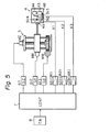
- FIG. 5 an industrial robot 5 having the hand 4 shown in Figs. 3 and 4 and the control flow thereof are illustrated.
- the industrial robot 5 is controlled by a robot control device (CONT) 7.
- CONT robot control device
- the robot control device 7 controls the position of the hand 4 and also controls the operations of the solenoid valves SV 2 , SV 3 and SV 4 disposed in the hand 4, whereby not only opening and closing of the finger mechanisms 41 and 42 of the hand 4 but also switching of the grasping force can be controlled.
- the grasping force of the hand 4 can be preset in the teaching mode of the teaching box 8, depending upon the kind and state of the article to be gripped by the hand 4.
- a device for operating a hand of an industrial robot in which the grasping force can be controlled depending upon the state of the article to be gripped.
Landscapes
- Engineering & Computer Science (AREA)
- Robotics (AREA)
- Mechanical Engineering (AREA)
- Human Computer Interaction (AREA)
- Manipulator (AREA)
Abstract
A device for operating the hand of an industrial robot, in which hydraulic cylinders (43, 44) are provided as a mechanism for driving the hand (4), a passage including a pressure reducing valve (47) is branched to the fluid supply passage of the cylinders (43, 44), the fluid supply is switched by solenoid valves (SV2, SV3, SV4), which are controlled to be switched on the basis of the instruction of the holding force set in the teaching mode of the robot, thereby enabling control of the holding force of the hand in multiple steps.
Description
- A Device for Operating a Hand of an Industrial Robot
- The present invention relates to a device for operating a hand of an industrial robot. More particularly, it relates to a device for operating a hand of an industrial robot whose grasping force can be controlled stepwisely.
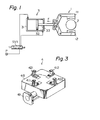
- As a device for operating a hand of an industrial robot, there has heretofore been used one in which, as illustrated in Fig. 1, an air cylinder is driven by a fixed pneumatic pressure so as to generate the grasping force of the hand.
- In the device for operating the hand of the industrial robot as shown in Fig. 1, a finger-driving mechanism 1 is so constructed as to open or close the
finger portions 11 and 12 in accordance with the movement of the piston 31 of theair cylinder 3. Accordingly, the force with which thefinger portions 11 and 12 grasp an article to be gripped 2 is determined by the thrust F of theair cylinder 3. This thrust F is given by the following expression:
- Here, S donotes the pressure-receiving area of the piston, P the pneumatic pressure in the cylinder, and n the efficiency.
- Accordingly, the thrust F is uniquely determined by the feed pressure of the air so that the grasping force of the hand becomes constant. Therefore, in the device for operating the hand of the industrial robot as shown in Fig. 1, the article to be gripped 2 is gripped with a constant grasping force which is determined by the feed pressure of the air P. This leads to a problem in which the grasping force cannot be switched in accordance with the state of the article to be gripped, and in some cases the article to be gripped is broken.
- The principal object of the present invention is to provide a device for operating a hand of an industrial robot in which the grasping force can be controlled in accordance with the state of the object to be gripped, in view of the. problem of the prior art described above and on the basis of the concept of a passage which includes a pressure-reducing valve and which branches from a fluid supply passage for a fluid pressure cylinder so as to switch fluid feed by a solenoid valve.
- In accordance with the present invention, there is provided a device for operating a hand of an industrial robot, comprising fluid pressure cylinders as a driving mechanism of the hand of the industrial robot, branch passages including pressure-reducing valves being provided in a fluid supply passage to said fluid pressure cylinder, the supply of fluid being switched by solenoid valves, the switching of said solenoid valves being carried out in accordance with the grasping force which has been selected in a teaching mode of said industrial robot, whereby the grasping force of said hand is adapted so that it can be controlled stepwisely.
-
- Figure 1 illustrates a driving mechanism for the hand of an industrial robot of a prior-art;
- Fig. 2 illustrates a diagram of the drive flow of a device for operating a hand of an industrial robot in accordance with an embodiment of the present invention;
- Fig. 3 illustrates an external view of the hand of the industrial robot of Fig. 2;
- Fig. 4 illustrates the arrangement of the interior of the hand of Fig. 3; and
- Fig. 5 illustrates a control-flow diagram of an industrial robot having the hand of Fig. 2.
- A device for operating a hand of an industrial robot in accordance with an embodiment of the present invention is illustrated in Figs. 2, 3 and 4. In Fig. 2, the control flow of a
hand 4 according to the present invention is illustrated. An external view of thehand 4 is illustrated in Fig. 3, and the interior mechanism of thehand 4 is shown in Fig. 4. As illustrated in Figs. 2 and 3, thehand 4 has two sets offinger mechanisms finger mechanisms air cylinders air cylinder 43 is driven in the direction of the arrow.as indicated in Fig. 2, thefinger mechanism 41 is closed, and when the piston of theair cylinder 43 is driven in the direction opposite to the arrow, thefinger mechanism 41 is opened. The drive direction of theair cylinder 43 is controlled by a solenoid valve SV2, whereby opening and closing of thefinger mechanism 41 is controlled. The operation of thefinger mechanism 42 is similar to the above, and the opening and closing of thefinger mechanism 42 is controlled by a solenoid valve SV3. Switching of the solenoid valves SV2 and SV3, respectively, is controlled by electric signals X1 and X2. - The solenoid valves SV2 and SV3 are fed air through a common air passage PC. Two channels of air passages PA and PB are branched from an air supply source PS through a solenoid valve SV4 and are connected to the air passage PC. The air passage PA is provided with a
check valve 45, and the air passage PB is provided with a pressure-reducingvalve 47 and acheck valve 46. In the solenoid valve SV4, the air passage PA or PB is selected as the air passage to be connected to the air supply source PS. The air passage which is not connected to the air supply source PS is opened on the atmosphere side. First, assuming that the air passage PA is connected to the air supply source PS, the air is fed to the air passage PC through the solenoid valve SV4 as well as thecheck valve 45. Further, it is fed to theair cylinder 43 through the solenoid valve SV2 and to theair cylinder 44 through the solenoid valve SV3. The counter flow of the air from the air passage PC to the air passage PB is prevented by thecheck valve 46. In this case, a pneumatic pressure P1 in the air supply source is fed to theair cylinders valve 47 as well as thecheck valve 46. Further, it is fed to theair cylinder 43 through the solenoid valve SV2 and to theair cylinder 44 through the solenoid valve SV3. The counter flow of the air from the air passage PC to the air passage PA is prevented by thecheck valve 45. Supposing that a pneumatic pressure P2 lower than P1 is present in the pressure-reducingvalve 47, the pneumatic pressure which is fed to theair cylinders air cylinders 

- Here, PI and P2 denote the pneumatic pressures, S the pressure-receiving area of the air cylinder, and n the efficiency.
- The switching of the pneumatic pressures is controlled by an electric signal X3 which is applied to the solenoid valve SV 4.
- The
aforementioned finger mechanisms air cylinders check valves casing 48 of thehand 4 as shown in Figure 4. - In Fig. 5, an
industrial robot 5 having thehand 4 shown in Figs. 3 and 4 and the control flow thereof are illustrated. Theindustrial robot 5 is controlled by a robot control device (CONT) 7. In accordance with a teaching mode previously set in a taching box (T. B.) 8, therobot control device 7 controls the position of thehand 4 and also controls the operations of the solenoid valves SV2 , SV3 and SV4 disposed in thehand 4, whereby not only opening and closing of thefinger mechanisms hand 4 but also switching of the grasping force can be controlled. Accordingly, the grasping force of thehand 4 can be preset in the teaching mode of the teaching box 8, depending upon the kind and state of the article to be gripped by thehand 4. - While in the
hand 4 shown in Fig. 2 the grasping force thereof is switched between the two values, it can of course be set so as to be switched in three or more stages if necessary. - In addition, while the above-mentioned embodiment has been described as employing air as the pressure medium, it is also possible to employ a different fluid.
- According to the present invention, there can be provided a device for operating a hand of an industrial robot in which the grasping force can be controlled depending upon the state of the article to be gripped.
-
- 1 ... finger-driving mechanism
- 11, 12 ... finger portions
- 2 ... article to be gripped
- 3 ... air cylinder
- 31 ... cylinder casing
- 32 ... piston
- 33 ... shaft
- 4 ... hand
- 41, 42 ... finger-driving mechanisms
- 411, 412, 421, 422 ... finger portions
- 43, 44 ... air cylinders
- 45, 46 ... check valves
- 47 ... pressure-reducing valves
- 48 ... casing
- 49 ... joint
- 5 ... industrial robot
- 611, 612, 613 ... motor-driving circuits
- 621, 622, 623 ... solenoid valve-driving circuits
- 7 ... robot-control device
- 8 ... teaching box
- SV1, SV2, SV3, SV4 ... solenoid valves
- PA ' PB' PC, PS ... air passages
- MZ, MR, Mθ ... driving motors
Claims (3)
1. A device for operating a hand of an industrial robot, comprising fluid pressure cylinders as a driving mechanism of the hand of the industrial robot, branch passages including pressure reducing valves being provided in a fluid supply passage to said fluid pressure cylinder, the supply of fluid being switched by solenoid valves, the switching of said solenoid valves being carried out in -accordance with the selected grasping force which has been selected in a teaching mode of said industrial robot, whereby the grasping force of said hand is adapted so that it can be controlled stepwisely.
2. A device for operating a hand of an industrial robot as defined in claim 1, comprising:
two sets of finger mechanisms which are adapted so that they can be driven in forward and backward directions and rightward and leftward directions;
air cylinders for driving said finger mechanisms;
first and second solenoid valves for controlling the drive directions of said air cylinders;
means for supplying electric signals to said first and second solenoid valves;
air passages for feeding air to said first and second solenoid valves;
a third solenoid valve for controlling the air supplied to said air passage;
means for supplying an electric signal to said third solenoid valve; and
an air supply source for supplying air to said third solenoid valve.
3. A device for operating a hand of an industrial robot as defined in claim 1, further comprising:
a teaching box;
a robot-controlling means receiving a signal from said teaching box;
Z-, 6-, and R-motion-driving circuits receiving motor-driving signals from said robot control device;
motors for driving Z-, θ-, and R-motions of said industrial robot, said motors receiving the output signals of said Z-, e- and, R-motion-driving circuits;
first, second, and third solenoid valve--driving circuits receiving solenoid valve-driving signals from said robot-controlling means; and
first, second, and third solenoid valves for said industrial robot hand, said solenoid valves receiving the output signals of said first, second, and third solenoid valve-driving circuits, respectively.
Applications Claiming Priority (2)
| Application Number | Priority Date | Filing Date | Title |
|---|---|---|---|
| JP139914/80 | 1980-10-08 | ||
| JP55139914A JPS5766887A (en) | 1980-10-08 | 1980-10-08 | Hand for industrial robot |
Publications (2)
| Publication Number | Publication Date |
|---|---|
| EP0062069A1 true EP0062069A1 (en) | 1982-10-13 |
| EP0062069A4 EP0062069A4 (en) | 1984-03-01 |
Family
ID=15256578
Family Applications (1)
| Application Number | Title | Priority Date | Filing Date |
|---|---|---|---|
| EP19810902756 Withdrawn EP0062069A4 (en) | 1980-10-08 | 1981-10-07 | Device for operating hand of industrial robot. |
Country Status (5)
| Country | Link |
|---|---|
| US (1) | US4530636A (en) |
| EP (1) | EP0062069A4 (en) |
| JP (1) | JPS5766887A (en) |
| KR (1) | KR850000043B1 (en) |
| WO (1) | WO1982001155A1 (en) |
Cited By (1)
| Publication number | Priority date | Publication date | Assignee | Title |
|---|---|---|---|---|
| EP0114096A1 (en) * | 1983-01-13 | 1984-07-25 | Western Electric Company, Incorporated | Robotic arm |
Families Citing this family (11)
| Publication number | Priority date | Publication date | Assignee | Title |
|---|---|---|---|---|
| JPS59124589A (en) * | 1982-12-28 | 1984-07-18 | 株式会社東芝 | Industrial robot |
| DE3404553C2 (en) * | 1984-02-09 | 1986-04-17 | Carl Hurth Maschinen- und Zahnradfabrik GmbH & Co, 8000 München | Handling device, in particular for loading and unloading machine tools |
| JPS61241039A (en) * | 1985-04-16 | 1986-10-27 | Nippei Toyama Corp | Confirming device for clamp |
| JPS62199387A (en) * | 1986-02-26 | 1987-09-03 | オークマ株式会社 | Method and device for automatically adjusting gripping forceof robot hand |
| US5000652A (en) * | 1986-09-22 | 1991-03-19 | International Business Machines Corporation | Wafer transfer apparatus |
| US6592317B1 (en) * | 1995-03-07 | 2003-07-15 | Asyst Technologies, Inc. | Pod loader interface end effectors |
| EP1536677A4 (en) * | 2002-07-19 | 2006-11-15 | Matsushita Electric Ind Co Ltd | Part inserting head device, part inserting device, and part inserting method |
| US9014857B2 (en) | 2012-01-13 | 2015-04-21 | Toyota Motor Engineering & Manufacturing North America, Inc. | Methods and computer-program products for generating grasp patterns for use by a robot |
| US9014850B2 (en) | 2012-01-13 | 2015-04-21 | Toyota Motor Engineering & Manufacturing North America, Inc. | Methods and computer-program products for evaluating grasp patterns, and robots incorporating the same |
| US8843235B2 (en) | 2012-01-13 | 2014-09-23 | Toyota Motor Engineering & Manufacturing North America, Inc. | Robots, computer program products, and methods for trajectory plan optimization |
| US11154993B2 (en) | 2019-12-11 | 2021-10-26 | Delaware Capital Formation, Inc. | Tool changer |
Citations (1)
| Publication number | Priority date | Publication date | Assignee | Title |
|---|---|---|---|---|
| GB2041263A (en) * | 1979-02-06 | 1980-09-10 | Asea Ab | Gripping device for moving workpieces relative to a machine tool |
Family Cites Families (7)
| Publication number | Priority date | Publication date | Assignee | Title |
|---|---|---|---|---|
| US2642307A (en) * | 1949-01-26 | 1953-06-16 | American Brake Shoe Co | Grab |
| GB955005A (en) * | 1961-07-21 | 1964-04-08 | Molins Machine Co Ltd | Apparatus for gripping and lifting articles |
| US3410431A (en) * | 1966-07-06 | 1968-11-12 | Inventors Engineering | Clamp mechanism for materials handling equipment |
| US3851769A (en) * | 1971-04-09 | 1974-12-03 | Seiko Instr & Electronics | Industrial robot |
| JPS5148350B2 (en) * | 1971-06-08 | 1976-12-20 | ||
| JPS516939B2 (en) * | 1971-06-29 | 1976-03-03 | ||
| DE2808175A1 (en) * | 1978-02-25 | 1979-08-30 | Oldenburger Betonsteinwerke | Clamping and aligning frame for paving assembly - has frame with one cylinder for all lever connected clamping beams (NL 28.8.79) |
-
1980
- 1980-10-08 JP JP55139914A patent/JPS5766887A/en active Granted
-
1981
- 1981-10-05 KR KR1019810003743A patent/KR850000043B1/en active
- 1981-10-07 WO PCT/JP1981/000267 patent/WO1982001155A1/en not_active Application Discontinuation
- 1981-10-07 EP EP19810902756 patent/EP0062069A4/en not_active Withdrawn
- 1981-10-07 US US06/387,886 patent/US4530636A/en not_active Expired - Fee Related
Patent Citations (1)
| Publication number | Priority date | Publication date | Assignee | Title |
|---|---|---|---|---|
| GB2041263A (en) * | 1979-02-06 | 1980-09-10 | Asea Ab | Gripping device for moving workpieces relative to a machine tool |
Non-Patent Citations (1)
| Title |
|---|
| See also references of WO8201155A1 * |
Cited By (1)
| Publication number | Priority date | Publication date | Assignee | Title |
|---|---|---|---|---|
| EP0114096A1 (en) * | 1983-01-13 | 1984-07-25 | Western Electric Company, Incorporated | Robotic arm |
Also Published As
| Publication number | Publication date |
|---|---|
| JPS6125513B2 (en) | 1986-06-16 |
| US4530636A (en) | 1985-07-23 |
| JPS5766887A (en) | 1982-04-23 |
| WO1982001155A1 (en) | 1982-04-15 |
| KR830007234A (en) | 1983-10-19 |
| EP0062069A4 (en) | 1984-03-01 |
| KR850000043B1 (en) | 1985-02-14 |
Similar Documents
| Publication | Publication Date | Title |
|---|---|---|
| EP0062069A1 (en) | Device for operating hand of industrial robot | |
| EP1080323B1 (en) | Electrically controllable valve | |
| JPS63254203A (en) | Controller for piston in double operation cylinder | |
| US6003428A (en) | Electro-pneumatic pressure control system for welding and like apparatus | |
| CA2174011A1 (en) | Hydraulic control system providing proportional movement to an attachment of a power machine | |
| US6371162B1 (en) | Electric actuator for fluid control valves | |
| KR900700771A (en) | Hydraulic Drive Method and Hydraulic Drive of Hydraulic Machine | |
| CA2173267A1 (en) | Fluid Control System and Valve to Be Used Therein | |
| EP0062070A1 (en) | Device for operating hand of industrial robot | |
| US5484352A (en) | Switch for detecting operation of control valve spool | |
| US3123230A (en) | Manipulators | |
| EP0822344A3 (en) | Pneumatic control device and a block valve for such a device | |
| US6349627B1 (en) | Electropneumatic positioner | |
| ATE169132T1 (en) | ELECTROHYDRAULIC CONTROL DEVICE AND PRESSURE REDUCING VALVE | |
| JPH0448324Y2 (en) | ||
| EP0751303A3 (en) | Hydraulic drive and control system | |
| EP1209394A3 (en) | Electro-hydraulic actuator | |
| EP0074829A2 (en) | A system for moving a member | |
| JPH0414643Y2 (en) | ||
| JPH0448323Y2 (en) | ||
| JPH0649641Y2 (en) | Load handling speed switching device for skid steer loader | |
| JPH0685980U (en) | Time division control hydraulic actuator | |
| EP0219293B1 (en) | Pneumatic control system for vehicles | |
| GB903929A (en) | Improvements in or relating to hydraulic machines | |
| FR2653243B1 (en) |
Legal Events
| Date | Code | Title | Description |
|---|---|---|---|
| PUAI | Public reference made under article 153(3) epc to a published international application that has entered the european phase |
Free format text: ORIGINAL CODE: 0009012 |
|
| 17P | Request for examination filed |
Effective date: 19820603 |
|
| AK | Designated contracting states |
Designated state(s): DE FR GB |
|
| RAP1 | Party data changed (applicant data changed or rights of an application transferred) |
Owner name: FANUC LIMITED |
|
| STAA | Information on the status of an ep patent application or granted ep patent |
Free format text: STATUS: THE APPLICATION IS DEEMED TO BE WITHDRAWN |
|
| 18D | Application deemed to be withdrawn |
Effective date: 19850624 |
|
| RIN1 | Information on inventor provided before grant (corrected) |
Inventor name: INABA, HAJIMU Inventor name: SAKAKIBARA, SHINSUKE Inventor name: NIHEI, RYO |