EP0062006A2 - Verfahren und Gerät zur wiederholten Ablenkung eines Bündels kohärenter Strahlung - Google Patents
Verfahren und Gerät zur wiederholten Ablenkung eines Bündels kohärenter Strahlung Download PDFInfo
- Publication number
- EP0062006A2 EP0062006A2 EP82810138A EP82810138A EP0062006A2 EP 0062006 A2 EP0062006 A2 EP 0062006A2 EP 82810138 A EP82810138 A EP 82810138A EP 82810138 A EP82810138 A EP 82810138A EP 0062006 A2 EP0062006 A2 EP 0062006A2
- Authority
- EP
- European Patent Office
- Prior art keywords
- light
- deflexion
- output elementary
- output
- saw
- Prior art date
- Legal status (The legal status is an assumption and is not a legal conclusion. Google has not performed a legal analysis and makes no representation as to the accuracy of the status listed.)
- Withdrawn
Links
- 238000000034 method Methods 0.000 title claims abstract description 20
- 230000005855 radiation Effects 0.000 title claims abstract description 17
- 230000001427 coherent effect Effects 0.000 title claims abstract description 11
- 230000033001 locomotion Effects 0.000 claims abstract description 33
- 230000010287 polarization Effects 0.000 claims abstract description 33
- 230000037361 pathway Effects 0.000 claims abstract description 23
- 230000003287 optical effect Effects 0.000 claims description 15
- 230000005540 biological transmission Effects 0.000 claims description 9
- 230000010363 phase shift Effects 0.000 claims description 5
- 230000010349 pulsation Effects 0.000 claims description 5
- 239000004020 conductor Substances 0.000 claims description 2
- 239000000758 substrate Substances 0.000 claims description 2
- 238000010586 diagram Methods 0.000 description 3
- 238000005553 drilling Methods 0.000 description 2
- 238000006073 displacement reaction Methods 0.000 description 1
- 238000011067 equilibration Methods 0.000 description 1
- 238000003754 machining Methods 0.000 description 1
- 238000004886 process control Methods 0.000 description 1
- 238000000926 separation method Methods 0.000 description 1
Images


Classifications
-
- G—PHYSICS
- G02—OPTICS
- G02F—OPTICAL DEVICES OR ARRANGEMENTS FOR THE CONTROL OF LIGHT BY MODIFICATION OF THE OPTICAL PROPERTIES OF THE MEDIA OF THE ELEMENTS INVOLVED THEREIN; NON-LINEAR OPTICS; FREQUENCY-CHANGING OF LIGHT; OPTICAL LOGIC ELEMENTS; OPTICAL ANALOGUE/DIGITAL CONVERTERS
- G02F1/00—Devices or arrangements for the control of the intensity, colour, phase, polarisation or direction of light arriving from an independent light source, e.g. switching, gating or modulating; Non-linear optics
- G02F1/29—Devices or arrangements for the control of the intensity, colour, phase, polarisation or direction of light arriving from an independent light source, e.g. switching, gating or modulating; Non-linear optics for the control of the position or the direction of light beams, i.e. deflection
- G02F1/31—Digital deflection, i.e. optical switching
Definitions
- Deflecting devices of laser beams for obtaining a saw-tooth motion of the emerging beam generally consist of a reflector provided with an adequate movement, usually an angular movement.
- a reflector with one reflecting surface is actuated at a constant angular velocity in one direction and at a much greater velocity in the return direction.
- the return time should be null. But for typical value of the frequency of the forth and back movement of 5 kHz, the displacement of a mechanical device at such velocities for the return direction is difficult to achieve.
- Polygonal reflectors with a constant angular speed enable to overcome the problem of accelerating and decelerating a mass at high frequencies.
- Such deflecting devices present however two draw backs. The first one is that the impinging beam slides along the reflecting surface. Indeed, the axis of rotation can no longer be confounded with the reflecting surfaces at the point of impact of the beam. Therefore the emerging beam is no longer linearly deviated with time.
- the second one results from the passage from one reflecting surface to the other. At that instant the light-beam is scattered in two directions and represents lost energy.
- the laser beam is made to follow a plurality of N optical pathes, the choice ot the pathes being dictated, according to a sequential law,by the direction of polarization of the radiation.
- Each optical path leads to a scanner which deflects the light with a certain periodicity, the phase shift between each scanners being an inverse ratio of the number of optical pathes.
- the method of the invention for repeatly deflecting a beam of coherent radiation for obtaining a substantial saw-tooth motion of this beam comprises the steps of making a sequential polarization of the radiation so as to generate N successive output elementary beams of corresponding polarization. This sequential polarization occurs at a frequency equal to the frequency of the saw-tooth motion of the beam. A sequential deflexion of the output elementary beams is then done, each output elementary'beam being successively deflected of a same given angular value according to a substantial sine law before the commutation of the deflexion to next output elementary beam.
- the output elementary beams are each deflected according to a same path-way.
- the pattern of the light-beam with respect to time therefore follows an approximate saw-tooth for which the return time is reduced pratically to zero.
- the method of the invention and the device for carrying it out are particularly of interest to engrave intaglio printing forms or drums by using gating or pulse length modulation.
- Method and apparatus to engrave intaglio printing forms have been disclosed in US patent 4 131 782 in the name of the applicant.
- the method of the invention can also be used for dynamic equilibration of rotating devices.
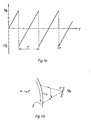
- Drawing la illustrates the saw-tooth function an ideal scanner is expected to perform, the abscissa being the time scale and the ordinates the scanning amplitude in radians.
- the return time T r is ideally null, in practice it should be as small as possible.
- Such scanner is used for example for deviating a laser beam so it made to follow a spot or small area on a moving object as shown figure lb. This technique is used for instance for machining, engraving or drilling holes on moving objects in which a laser beam is used to engrave intaglio printing forms requiring the drilling of a large number of printing cells on a rotating cylinder.
- the laser beam should precisely follow the spot or area S on the printing form until the cell has reached the desired size without blurring.
- the saw-tooth function of figure la is approximated by the function of figure 2.
- the beam of coherent radiation is made to undergo a sequential polarization so as to generate N successive output elementary beams of corresponding polarization.
- the beam of coherent radiation is chopped into output elementary beams of corresponding polarization constituting the resulting beam.
- the sequential polarization occurs at a frequency equal to the frequency of the saw-tooth motion of the beam.
- Each of the output elementary beams are the successively deflected of a same given angular value a according to a substantial sine law before the commutation of the deflexion to the next output elementary beam.
- Each output elementary beam is deflected according to a same path-way L as shown Figure lb.
- the coefficient k is substantially equal to in which w is the angular speed of the rotating body or pulsation of the sine law deflexion for each output elementary beam and T the duration of scanning along the common path-way for each output elementary beam.
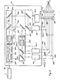
- the apparatus for deflecting a light-beam of coherent radiation 10 generated by a laser generator 1 comprises a device 2 for separating the light beam 10 into at least N distinct optical pathes of corresponding polarization.
- the optical pathes are labelled 10p, 10p + 1 to 10 N + p - 1 and are represented by the sequential laser beam path. At least, N successive elementary beam are thus generated according to a given sequential law.
- a device 3 allows then to produce a successive sequential deflexion of a number N of output elementary beams.
- Each of the output elementary beams are successively deflected of a same angular value according to a substantial sine law before the commutation of the deflexion to the next output elementary beam.
- output elementary beams 10p to ION + p - 1 are directed towards device 3 by means of fixed mirrors 200.
- An optical device 4 such as a converging lens allows thus the deflected output elementary beams to be focused along a common path-way L. A substantial saw-tooth motion of the light-beam is thus generated onto common path-way L.
- the device 2 for separating the light-beam into at least N distinct optical pathes comprises in succession an ON - OFF switching unit 20 allowing the transmission or the deviation of the light beam 10.
- the laser beam 10 After transmission through ON - OFF switching unit 20 the laser beam 10 enters a first separating unit 21 disposed on the optical path of said light-beam 10.
- the first separating unit 21 may substantially consist in succession of a circular polarizer strip 211 followed by a unit 212 for the polarization of the ON-OFF switched light-beam along two perpendicular directions according to a given time sequence.
- a first polarizer beam splitter 213 reflects light of beam 10 when polarized in the corresponding parallel first direction and let it through when polarized at second perpendicular direction and reverse.
- the first polarizer beam splitter 213 and a following mirror 214 allow thus successive elementary beams 101, 102 to be generated by change of the optical path of laser beam 10.
- a control unit 2c allows the generation of the time sequence of the successive output elementary beams according to the saw-tooth motion.
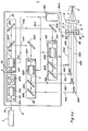
- the control unit 2c is connected with a control input of each polarization unit 212, 222, ... 2N2, such as 212 in first separating unit, for the polarization of the ON - OFF switched light-beam or elementary beam along two perpendicular directions.
- Control unit 2c allows thus the polarization switching between first and second perpendicular direction according to a chosen sequential time law.
- FIG 3 connections between control unit 2c and separating unit 21, 22 ... 2N are represented in 2c 1 with dotted lines in order to overcome confusion of light-beam 10 or elementary beam 101, 102 with connexions. A number of arrows on dotted lines corresponds to a same number of independant control ways for each separating unit.
- the unit for the polarization of the ON -. OFF switched light-beam 10 or elementary beam 101, 102 consists of a a/4 circular polarizer strip 212, 221 ... followed by a Pockell-cell 212, 222 for each separating unit.
- the Pockell-cell allows the polarization of the light-beam 10, or 101, 1 0 2, along two distinct perpendicular directions related to a sequential control voltage.
- the sequential control voltages for controlling the Pockell-cells, 212, 222, ... are generated by control unit 2c and applied to the Pockell-cells by connexions 2cl represented in dotted lines.
- the emerging beam from the Pockell-cell is linearly polarized along one direction or another (which is incidentally at right angles) depending on the sign of the electric voltage applied through each independant control way.
- the first polarizer beam splitters such as 223, 213,... consists each of an array of parallel metallic conductors (amplitude grating) or non metallic (phase grating) supported on a suitable substrate. The direction of reflexion of each array is perpendicular.
- Such kind of polarizer are commercialised for example by Cambridge Physical Sciences, Cambridge, England or by II - VI Inc. Glenshaw, Pennsylvania, USA.
- the output elementary beams 10p to 10 N + p - 1 are led through reflecting mirrors to a deflecting device 3 for producing a successive sequential deflexion of each output elementary beam according to a sine law.
- Deflecting device 3 is provided with N scanners labelled 31 to 3N each scanner receiving one output elementary beam for deflexion.
- Each scanner 31 to 3N may consist of a vibrating mirror or rotating mirrors. Vibrating mirrors or rotating mirrors are driven by classical motors which are not shown on Figure 3 since these are well known from one skilled in the art.
- Scanners 31 to 3N are controlled by control unit 2c through N independant control channels 2c 2 .
- Control untit 2c allows the deflexion of each output elementary beams to be phase-shifted from one to the next of an amount in which Control unit 2c allows thus for the light-beam a saw-tooth motion frequency to be selected and generated.
- each elementary beam is deflected of an angle
- Control unit 2c allows thus for a particular application of the method and apparatus of the invention linearity and frequency of saw-tooth motion to be optimized.
- the number of scanners driven by control unit 2c may be chosen inferior to the actual number of output elementary beams so as to get an odd number of output elementary beams after deflexion.
- control unit 2c may consist of a micro-computer adapted for process-control.
- Deflected output elementary beams are directed towards a focussing device 4.
- Focusing device 4 allows them to be focused according to a common path-way L and may consist of a focusing lens.
- scanners can direct the light to the desired spot on the moving object.
- Focusing lens 4 directs both beams after deflexion to the same spot on the object. This procedure is easily realised since both beams have parallel directions; the lens is then placed at a focal distance from the object to be treated.
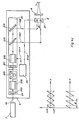
- Figure 3 shows a diagram from a) to i) in which different forms of signals or light polarization states are given with respect to time t at corresponding points A, B, C, D, E, F, G, H, I, of figure 4a.
- the light-beam transmitted by ON - OFF switching circuit 20 has a given polarization direction represented by vertical lines when light is transmitted.
- first separating unit 21 after transmission through Pockell-cell 212 the polarization direction of beam 10 at point B is changed into a perpendicular polarization direction represented by horizontal lines according to a sequential law given by a first control signal generated by control unit 2c.
- This signal is represented in Figure 4b, b) by a rectangular wave form of frequency being the saw-tooth frequency.
- Figure 4b c) and d) represent the digital treatment of elementary beams 101 and 102 respectively through second and third separating units 22 and 23 substantially at points C and D after transmission by Pockell-cells 222 and 232.
- Second and third control signal allow, when changing their digital level 0 or 1, the corresponding change of polarization direction of light-beam transmitted by Pockell-cell 222 and 232 and the sequential separation of elementary beams 101 and 102 according to two further optical pathes 103, 105 and 104, 106 through polarizers 223 and 233.
- each striped zone with parallel vertical or horizontal lines respectively labelled 103, 105 and 104, 106 represents then the sequential law of transmission of output elementary beams such as 103, 105 and 104, 106.
- Figures 4b e, f, g, h represent the sine law deflexion for each scanner 31, 32, 33, 34 respectively.
- the deflexion of the output elementary beams is phase-shifted from one to the next of an amount of
- N 2 according to Figure 4 c.
- the same references represent the same elements that were shown in Figure 4a.
- second and third separating unit 22 and 23 have been removed so that elementary beams 101 and 102 are directly used as output elementary beams and both directed towards scanners 31 and 32.
Landscapes
- Physics & Mathematics (AREA)
- Nonlinear Science (AREA)
- General Physics & Mathematics (AREA)
- Optics & Photonics (AREA)
- Analysing Materials By The Use Of Radiation (AREA)
- Lasers (AREA)
Applications Claiming Priority (2)
| Application Number | Priority Date | Filing Date | Title |
|---|---|---|---|
| US24919381A | 1981-03-30 | 1981-03-30 | |
| US249193 | 1981-03-30 |
Publications (2)
| Publication Number | Publication Date |
|---|---|
| EP0062006A2 true EP0062006A2 (de) | 1982-10-06 |
| EP0062006A3 EP0062006A3 (de) | 1985-12-04 |
Family
ID=22942424
Family Applications (1)
| Application Number | Title | Priority Date | Filing Date |
|---|---|---|---|
| EP82810138A Withdrawn EP0062006A3 (de) | 1981-03-30 | 1982-03-26 | Verfahren und Gerät zur wiederholten Ablenkung eines Bündels kohärenter Strahlung |
Country Status (1)
| Country | Link |
|---|---|
| EP (1) | EP0062006A3 (de) |
Family Cites Families (2)
| Publication number | Priority date | Publication date | Assignee | Title |
|---|---|---|---|---|
| US3513323A (en) * | 1965-12-13 | 1970-05-19 | Ibm | Light beam deflection system |
| DE1589980A1 (de) * | 1967-11-18 | 1971-03-18 | Ibm Deutschland | Anordnung zur steuerbaren Ablenkung eines Lichtstrahls |
-
1982
- 1982-03-26 EP EP82810138A patent/EP0062006A3/de not_active Withdrawn
Also Published As
| Publication number | Publication date |
|---|---|
| EP0062006A3 (de) | 1985-12-04 |
Similar Documents
| Publication | Publication Date | Title |
|---|---|---|
| US4321564A (en) | Sequential beam switching of acousto-optic modulator | |
| US4378480A (en) | Device for the optical chopping of a laser beam | |
| EP0593538B1 (de) | Laserstrahl-abtastvorrichtung und verfahren | |
| US5231405A (en) | Time-multiplexed phased-array antenna beam switching system | |
| CA1166343A (en) | Image input device | |
| US4581617A (en) | Method for correcting beam intensity upon scanning and recording a picture | |
| US4801950A (en) | Multi-beam roller phototracer | |
| EP0291035B1 (de) | Vorrichtung zum Abtasten mit Lichtstrahlen | |
| US6008925A (en) | Light beam scanning apparatus and method | |
| US4180307A (en) | Two-dimensional scanning apparatus with constant speed scan | |
| US4250465A (en) | Radiation beam deflection system | |
| JPS6221304B2 (de) | ||
| GB2085652A (en) | Framing tube and framing camera | |
| US5446556A (en) | Video clock signal generator in an optical scanner in which a mask including a linear scale provides timing for controlling the amplitude of a vibrating mirror | |
| US12124158B2 (en) | Projection device and method for directing a light beam to a target | |
| US4329011A (en) | Method for driving a light scanning apparatus | |
| US3630594A (en) | Holographic scan converter | |
| EP0062006A2 (de) | Verfahren und Gerät zur wiederholten Ablenkung eines Bündels kohärenter Strahlung | |
| US4540245A (en) | Apparatus and method for acousto-optic character generation | |
| GB2103813A (en) | Light-writing | |
| WO1995005944A1 (en) | A printer and a print engine therefor | |
| JPH0675016B2 (ja) | 光サンプリング・システム | |
| EP0372943A3 (de) | Elektrophotographische Abbildungsstelle mit verbesserter Auflösung | |
| US5168167A (en) | Optical scanner having controllable light sources | |
| Lin et al. | Acousto-optic multichannel programmable true time delay lines |
Legal Events
| Date | Code | Title | Description |
|---|---|---|---|
| PUAI | Public reference made under article 153(3) epc to a published international application that has entered the european phase |
Free format text: ORIGINAL CODE: 0009012 |
|
| AK | Designated contracting states |
Designated state(s): CH DE FR GB NL |
|
| PUAL | Search report despatched |
Free format text: ORIGINAL CODE: 0009013 |
|
| AK | Designated contracting states |
Designated state(s): CH DE FR GB LI NL |
|
| STAA | Information on the status of an ep patent application or granted ep patent |
Free format text: STATUS: THE APPLICATION IS DEEMED TO BE WITHDRAWN |
|
| 18D | Application deemed to be withdrawn |
Effective date: 19851001 |
|
| RIN1 | Information on inventor provided before grant (corrected) |
Inventor name: SPRING, PETER |