EP0061935A2 - Process and apparatus for reducing melt fracture during extrusion of a molten narrow molecular weight distribution, linear, ethylene copolymer - Google Patents
Process and apparatus for reducing melt fracture during extrusion of a molten narrow molecular weight distribution, linear, ethylene copolymer Download PDFInfo
- Publication number
- EP0061935A2 EP0061935A2 EP82301705A EP82301705A EP0061935A2 EP 0061935 A2 EP0061935 A2 EP 0061935A2 EP 82301705 A EP82301705 A EP 82301705A EP 82301705 A EP82301705 A EP 82301705A EP 0061935 A2 EP0061935 A2 EP 0061935A2
- Authority
- EP
- European Patent Office
- Prior art keywords
- die
- die lip
- polymer
- film
- melt fracture
- Prior art date
- Legal status (The legal status is an assumption and is not a legal conclusion. Google has not performed a legal analysis and makes no representation as to the accuracy of the status listed.)
- Granted
Links
- 238000000034 method Methods 0.000 title claims abstract description 56
- 238000001125 extrusion Methods 0.000 title claims abstract description 45
- 230000008569 process Effects 0.000 title claims abstract description 41
- 238000009826 distribution Methods 0.000 title claims abstract description 18
- 229920001038 ethylene copolymer Polymers 0.000 title description 6
- 229920000642 polymer Polymers 0.000 claims abstract description 47
- 229920000573 polyethylene Polymers 0.000 claims abstract description 25
- 239000000155 melt Substances 0.000 claims description 19
- 229920001577 copolymer Polymers 0.000 claims description 18
- 239000005977 Ethylene Substances 0.000 claims description 13
- VGGSQFUCUMXWEO-UHFFFAOYSA-N Ethene Chemical compound C=C VGGSQFUCUMXWEO-UHFFFAOYSA-N 0.000 claims description 12
- 239000004711 α-olefin Substances 0.000 claims description 6
- 125000004432 carbon atom Chemical group C* 0.000 claims description 5
- 239000004215 Carbon black (E152) Substances 0.000 claims description 2
- 229930195733 hydrocarbon Natural products 0.000 claims description 2
- 229920005989 resin Polymers 0.000 description 24
- 239000011347 resin Substances 0.000 description 24
- 229920001684 low density polyethylene Polymers 0.000 description 15
- 239000004702 low-density polyethylene Substances 0.000 description 14
- 239000003054 catalyst Substances 0.000 description 8
- 238000001816 cooling Methods 0.000 description 6
- 230000000694 effects Effects 0.000 description 6
- 239000007789 gas Substances 0.000 description 6
- 239000000463 material Substances 0.000 description 6
- 239000000178 monomer Substances 0.000 description 6
- 238000004806 packaging method and process Methods 0.000 description 6
- 229920001519 homopolymer Polymers 0.000 description 5
- 230000015572 biosynthetic process Effects 0.000 description 4
- 230000003287 optical effect Effects 0.000 description 4
- 239000002356 single layer Substances 0.000 description 4
- 239000012876 carrier material Substances 0.000 description 3
- 238000006243 chemical reaction Methods 0.000 description 3
- 230000006872 improvement Effects 0.000 description 3
- 238000002156 mixing Methods 0.000 description 3
- 238000006116 polymerization reaction Methods 0.000 description 3
- 238000010791 quenching Methods 0.000 description 3
- 238000000518 rheometry Methods 0.000 description 3
- 229920001169 thermoplastic Polymers 0.000 description 3
- 239000004416 thermosoftening plastic Substances 0.000 description 3
- 230000000007 visual effect Effects 0.000 description 3
- XLYOFNOQVPJJNP-UHFFFAOYSA-N water Substances O XLYOFNOQVPJJNP-UHFFFAOYSA-N 0.000 description 3
- VXNZUUAINFGPBY-UHFFFAOYSA-N 1-Butene Chemical compound CCC=C VXNZUUAINFGPBY-UHFFFAOYSA-N 0.000 description 2
- 241000239290 Araneae Species 0.000 description 2
- IJGRMHOSHXDMSA-UHFFFAOYSA-N Atomic nitrogen Chemical compound N#N IJGRMHOSHXDMSA-UHFFFAOYSA-N 0.000 description 2
- UFHFLCQGNIYNRP-UHFFFAOYSA-N Hydrogen Chemical compound [H][H] UFHFLCQGNIYNRP-UHFFFAOYSA-N 0.000 description 2
- 230000007423 decrease Effects 0.000 description 2
- 235000013305 food Nutrition 0.000 description 2
- 239000001257 hydrogen Substances 0.000 description 2
- 229910052739 hydrogen Inorganic materials 0.000 description 2
- 238000004519 manufacturing process Methods 0.000 description 2
- 238000002844 melting Methods 0.000 description 2
- 230000008018 melting Effects 0.000 description 2
- 238000012986 modification Methods 0.000 description 2
- 230000004048 modification Effects 0.000 description 2
- 239000002685 polymerization catalyst Substances 0.000 description 2
- 230000000171 quenching effect Effects 0.000 description 2
- 230000009467 reduction Effects 0.000 description 2
- 230000004044 response Effects 0.000 description 2
- 239000007787 solid Substances 0.000 description 2
- LIKMAJRDDDTEIG-UHFFFAOYSA-N 1-hexene Chemical compound CCCCC=C LIKMAJRDDDTEIG-UHFFFAOYSA-N 0.000 description 1
- WSSSPWUEQFSQQG-UHFFFAOYSA-N 4-methyl-1-pentene Chemical compound CC(C)CC=C WSSSPWUEQFSQQG-UHFFFAOYSA-N 0.000 description 1
- 229920001342 Bakelite® Polymers 0.000 description 1
- 229910000968 Chilled casting Inorganic materials 0.000 description 1
- XDTMQSROBMDMFD-UHFFFAOYSA-N Cyclohexane Chemical compound C1CCCCC1 XDTMQSROBMDMFD-UHFFFAOYSA-N 0.000 description 1
- 241000251729 Elasmobranchii Species 0.000 description 1
- 241000276495 Melanogrammus aeglefinus Species 0.000 description 1
- 239000004698 Polyethylene Substances 0.000 description 1
- 239000000654 additive Substances 0.000 description 1
- 239000003963 antioxidant agent Substances 0.000 description 1
- 239000004637 bakelite Substances 0.000 description 1
- 230000004888 barrier function Effects 0.000 description 1
- 230000005540 biological transmission Effects 0.000 description 1
- 230000000903 blocking effect Effects 0.000 description 1
- 229910052799 carbon Inorganic materials 0.000 description 1
- 230000008859 change Effects 0.000 description 1
- 239000003795 chemical substances by application Substances 0.000 description 1
- 150000001875 compounds Chemical class 0.000 description 1
- 238000007796 conventional method Methods 0.000 description 1
- 238000007334 copolymerization reaction Methods 0.000 description 1
- 239000013078 crystal Substances 0.000 description 1
- 238000002425 crystallisation Methods 0.000 description 1
- 230000008025 crystallization Effects 0.000 description 1
- 230000003247 decreasing effect Effects 0.000 description 1
- 238000005108 dry cleaning Methods 0.000 description 1
- 230000008030 elimination Effects 0.000 description 1
- 238000003379 elimination reaction Methods 0.000 description 1
- 238000005516 engineering process Methods 0.000 description 1
- 239000012632 extractable Substances 0.000 description 1
- 239000012530 fluid Substances 0.000 description 1
- 235000012055 fruits and vegetables Nutrition 0.000 description 1
- 230000004927 fusion Effects 0.000 description 1
- 238000010438 heat treatment Methods 0.000 description 1
- 239000010410 layer Substances 0.000 description 1
- 229920005684 linear copolymer Polymers 0.000 description 1
- 239000007788 liquid Substances 0.000 description 1
- 239000002184 metal Substances 0.000 description 1
- 239000010813 municipal solid waste Substances 0.000 description 1
- 229910052757 nitrogen Inorganic materials 0.000 description 1
- 229920006280 packaging film Polymers 0.000 description 1
- 239000012785 packaging film Substances 0.000 description 1
- 239000002245 particle Substances 0.000 description 1
- YWAKXRMUMFPDSH-UHFFFAOYSA-N pentene Chemical compound CCCC=C YWAKXRMUMFPDSH-UHFFFAOYSA-N 0.000 description 1
- 230000035699 permeability Effects 0.000 description 1
- -1 polyethylene Polymers 0.000 description 1
- 238000002360 preparation method Methods 0.000 description 1
- 238000012545 processing Methods 0.000 description 1
- 230000000750 progressive effect Effects 0.000 description 1
- QQONPFPTGQHPMA-UHFFFAOYSA-N propylene Natural products CC=C QQONPFPTGQHPMA-UHFFFAOYSA-N 0.000 description 1
- 125000004805 propylene group Chemical group [H]C([H])([H])C([H])([*:1])C([H])([H])[*:2] 0.000 description 1
- 230000001681 protective effect Effects 0.000 description 1
- 230000001105 regulatory effect Effects 0.000 description 1
- 238000010008 shearing Methods 0.000 description 1
- 239000012748 slip agent Substances 0.000 description 1
- 238000010583 slow cooling Methods 0.000 description 1
- 238000001228 spectrum Methods 0.000 description 1
- 230000003068 static effect Effects 0.000 description 1
- 239000000126 substance Substances 0.000 description 1
- 239000004753 textile Substances 0.000 description 1
- 239000012815 thermoplastic material Substances 0.000 description 1
- 238000012546 transfer Methods 0.000 description 1
- 230000007704 transition Effects 0.000 description 1
- 238000004804 winding Methods 0.000 description 1
Images
Classifications
-
- B—PERFORMING OPERATIONS; TRANSPORTING
- B29—WORKING OF PLASTICS; WORKING OF SUBSTANCES IN A PLASTIC STATE IN GENERAL
- B29C—SHAPING OR JOINING OF PLASTICS; SHAPING OF MATERIAL IN A PLASTIC STATE, NOT OTHERWISE PROVIDED FOR; AFTER-TREATMENT OF THE SHAPED PRODUCTS, e.g. REPAIRING
- B29C48/00—Extrusion moulding, i.e. expressing the moulding material through a die or nozzle which imparts the desired form; Apparatus therefor
- B29C48/25—Component parts, details or accessories; Auxiliary operations
- B29C48/30—Extrusion nozzles or dies
- B29C48/32—Extrusion nozzles or dies with annular openings, e.g. for forming tubular articles
-
- B—PERFORMING OPERATIONS; TRANSPORTING
- B29—WORKING OF PLASTICS; WORKING OF SUBSTANCES IN A PLASTIC STATE IN GENERAL
- B29C—SHAPING OR JOINING OF PLASTICS; SHAPING OF MATERIAL IN A PLASTIC STATE, NOT OTHERWISE PROVIDED FOR; AFTER-TREATMENT OF THE SHAPED PRODUCTS, e.g. REPAIRING
- B29C48/00—Extrusion moulding, i.e. expressing the moulding material through a die or nozzle which imparts the desired form; Apparatus therefor
- B29C48/022—Extrusion moulding, i.e. expressing the moulding material through a die or nozzle which imparts the desired form; Apparatus therefor characterised by the choice of material
-
- B—PERFORMING OPERATIONS; TRANSPORTING
- B29—WORKING OF PLASTICS; WORKING OF SUBSTANCES IN A PLASTIC STATE IN GENERAL
- B29C—SHAPING OR JOINING OF PLASTICS; SHAPING OF MATERIAL IN A PLASTIC STATE, NOT OTHERWISE PROVIDED FOR; AFTER-TREATMENT OF THE SHAPED PRODUCTS, e.g. REPAIRING
- B29C48/00—Extrusion moulding, i.e. expressing the moulding material through a die or nozzle which imparts the desired form; Apparatus therefor
- B29C48/03—Extrusion moulding, i.e. expressing the moulding material through a die or nozzle which imparts the desired form; Apparatus therefor characterised by the shape of the extruded material at extrusion
- B29C48/07—Flat, e.g. panels
- B29C48/08—Flat, e.g. panels flexible, e.g. films
-
- B—PERFORMING OPERATIONS; TRANSPORTING
- B29—WORKING OF PLASTICS; WORKING OF SUBSTANCES IN A PLASTIC STATE IN GENERAL
- B29C—SHAPING OR JOINING OF PLASTICS; SHAPING OF MATERIAL IN A PLASTIC STATE, NOT OTHERWISE PROVIDED FOR; AFTER-TREATMENT OF THE SHAPED PRODUCTS, e.g. REPAIRING
- B29C48/00—Extrusion moulding, i.e. expressing the moulding material through a die or nozzle which imparts the desired form; Apparatus therefor
- B29C48/03—Extrusion moulding, i.e. expressing the moulding material through a die or nozzle which imparts the desired form; Apparatus therefor characterised by the shape of the extruded material at extrusion
- B29C48/09—Articles with cross-sections having partially or fully enclosed cavities, e.g. pipes or channels
- B29C48/10—Articles with cross-sections having partially or fully enclosed cavities, e.g. pipes or channels flexible, e.g. blown foils
-
- B—PERFORMING OPERATIONS; TRANSPORTING
- B29—WORKING OF PLASTICS; WORKING OF SUBSTANCES IN A PLASTIC STATE IN GENERAL
- B29C—SHAPING OR JOINING OF PLASTICS; SHAPING OF MATERIAL IN A PLASTIC STATE, NOT OTHERWISE PROVIDED FOR; AFTER-TREATMENT OF THE SHAPED PRODUCTS, e.g. REPAIRING
- B29C48/00—Extrusion moulding, i.e. expressing the moulding material through a die or nozzle which imparts the desired form; Apparatus therefor
- B29C48/25—Component parts, details or accessories; Auxiliary operations
- B29C48/30—Extrusion nozzles or dies
- B29C48/305—Extrusion nozzles or dies having a wide opening, e.g. for forming sheets
-
- B—PERFORMING OPERATIONS; TRANSPORTING
- B29—WORKING OF PLASTICS; WORKING OF SUBSTANCES IN A PLASTIC STATE IN GENERAL
- B29K—INDEXING SCHEME ASSOCIATED WITH SUBCLASSES B29B, B29C OR B29D, RELATING TO MOULDING MATERIALS OR TO MATERIALS FOR MOULDS, REINFORCEMENTS, FILLERS OR PREFORMED PARTS, e.g. INSERTS
- B29K2023/00—Use of polyalkenes or derivatives thereof as moulding material
- B29K2023/04—Polymers of ethylene
- B29K2023/06—PE, i.e. polyethylene
- B29K2023/0608—PE, i.e. polyethylene characterised by its density
- B29K2023/0633—LDPE, i.e. low density polyethylene
Definitions
- This invention relates to.a method for reducing melt fracture, particularly sharkskin melt fracture, during extrusion of a molten narrow molecular weight distribution, linear, ethylene copolymer, under conditions of flow rate and melt temperature which would otherwise produce such melt fracture.
- HP-LDPE high pressure, low density polyethylene
- HP-LDPE's are characterized by an intricate long chain branched molecular architecture. These long chain branches have a dramatic effect on the melt rheology of these resins.
- HP-LDPE's also possess a spectrum of short chain branches, generally 1 to 6 carbon atoms in length. These short chain branches disrupt crystal formation and depress resin density.
- low pressure technology whereby low density polyethylene can now be produced at low pressures and temperatures by copolymerizing ethylene with various alphaolefins.
- LP-LDPE low pressure LDPE
- resins generally possess little, if any, long chain branching. They are short chain branched with branch length and frequency controlled by the type and amount of comonomer used_ during polymerization.
- ethylene copolymers having a density of 0.91 to 0.96, a melt flow ratio of ⁇ 22 to ⁇ 32 and a relatively low residual catalyst content can be produced in granular form, at relatively high productivities, if the monomer(s) are copolymerized in a gas phase process with a specific high-activity Mg-Ti-containing complex catalyst which is impregnated in a porous inert carrier material.
- LP-LDPE resins can be extruded on equipment designed for HP-LDPE resins, certain equipment modifications are often required in order to extrude the low pressure resins at optimum conditions and at rates comparable to the high pressure resins. This is particularly true during extrusion of LP-LDPE which is processed into film. The problem appears to be that during extrusion of these particular resins, two aspects of rheological behavior play a significant role, i.e. shear and extension.
- a polymeric melt undergoes severe shearing deformation.
- the extrusion screw pumps the melt to, and through, the film die, the melt experiences a wide range of shear rates.
- Host film extrusion processes are thought to expose the melt to shear at rates in the 100-5000 sec -1 range.
- Polymeric melts are known to exhibit what is commonly termed shear thinning behavior, i.e., non-Newtonian flow behavior.
- shear rate is increased, viscosity (the ratio of shear stress, ⁇ , to shear rate, ⁇ ) decreases.
- the degree of viscosity decrease depends upon the molecular weight, its distribution, and molecular configuration, i.e., long chain branching of the polymeric material. Short chain branching has little effect on shear viscosity.
- high pressure low density polyethylenes have a broad molecular weight distribution and show enhanced shear thinning behavior in the shear rate range common to film extrusion.
- weight distribution resins used in the present invention exhibit reduced shear thinning behavior at extrusion shear rates.
- the consequences of these differences are that the narrow distribution resins used in the present invention require higher power and develop higher pressures during extrusion than the high pressure low density polyethylene resins of broad molecular weight distribution and of equivalent average molecular weight.
- shear viscosity in terms of shear stress and shear rate, i.i.:
- melt fracture Due to the high shear stress developed during extrusion of a high molecular weight ethylene polymer having a narrow molecular weight distribution, melt fracture, particularly sharkskin melt fracture, occurs.
- Sharkskin melt fracture has been described in the literature for a number of polymers.
- "Sharkskin” is a term used to describe a particular type of surface irregularity which occurs during extrusion of some thermoplastic materials under certain conditions. It is characterized by a series of ridges perpendicular to the flow direction and is described by J.A. Brydson, Flow Properties of Polymer Melts, Van Nostrand-Reinhold Company (1970), pages 78-81.
- the onset of sharkskin melt fracture is determined by visual observation of the surfaces of the film in its final form, i.e. after film winding. Specifically, this procedure for determining sharkskin melt fracture is as follows: The film is viewed and examined under a 20X magnification Nikon Profile Projector Model 6E using transmitted light.
- the film can be held up to light and visually examined by the naked eye to determine the presence, severity or absence of melt fracture.
- the narrow molecular weight distribution ethylene polymers as described herein exhibit the characteristics of sharkskin melt fracture upon extruding using the prior art extrusion processes. These characteristics include a pattern of wave distortion perpendicular to the flow direction; occurrence at low extrusion rates (less than expected for elastic turbulance); not effected by the use of commonly employed metal die materials; and less melt fracture with increasing temperature.
- 012,793 filed on February 16, 1979 discloses a process for forming blown tubular film essentially free of melt fracture by extruding the particular polymer through an extrusion die having a die gap of greater than about 50 mils and at a drawdown ratio of greater than about 2 to less than about 250.
- sharkskin melt fracture is reduced by extruding polymer through a die having a discharge outlet defining an exit die gap formed by opposing die lip surfaces and wherein one surface of the die lip and/or die land in contact with the molten polymer extends beyond the opposing surface of the die lip and/or die land in the direction of the axis of flow of the molten polymer through the die exit whereby melt fracture is reduced on the surface of the polymer leaving the extended die lip surface.
- melt fracture particularly sharkskin melt fracture
- melt fracture can be virtually eliminated on both surfaces of an extruded film formed from the polymers contemplated herein, by geometric changes in the die, i.e., by extruding the narrow molecular weight distribution .
- ethylene polymer at normal film extrusion temperatures through a die having a discharge outlet defining an exit die gap and wherein one surface of the die lip and/or die land in contact with the molten polymer extends beyond the opposing surface of the die lip and/or die land in the direction of the axis of flow of the molten polymer through the die exit and wherein said extended die lip has a groove extending around said extended die lip, said groove being disposed opposite the surface of the opposing die lip and preferably opposite the leading edge of the opposing die lip surface, whereby melt fracture is reduced on both surfaces of the polymer leaving said die lip exit.
- the utility of the process of the present invention arises due to the fact that the stress field at the exit of the die determines the creation of sharkskin melt fracture.
- sharkskin melt fracture can be controlled or eliminated by the geometry at the exit of the die.
- Films suitable for packaging applications must possess a balance of key properties for broad end-use utility and wide commercial acceptance. These properties include film optical quality, for example, haze, gloss, and see-through characteristics. Mechanical strength properties such as puncture resistance, tensile strength, impact strength, stiffness, and tear resistance are important. Vapor transmission and gas permeability characteristics are important considerations in perishable goods packaging. Performance in film converting and packaging equipment is influenced by film properties such as coefficient of friction, blocking, heat sealability and flex resistance. Low density polyethylene has a wide range of utility such as in food packaging and non-food packaging applications. ' Bags commonly produced from low density polyethylene include shipping sacks, textile bags, laundry and dry cleaning bags and trash bags.
- Low density polyethylene film can be used as drum liners for a number of liquid and solid chemicals and as protective wrap inside wooden crates. Low density polyethylene film can be used in a variety of agricultural and horticultural applications such as protecting plants and crops, as mulching, for storing of fruits and vegetables. Additionally, low density polyethylene film can be used in building applications such as a moisture or moisture vapor barrier. Further, low density polyethylene film can be coated and printed for use in newspapers, books, etc.
- high pressure low density polyethylene is the most important of the thermoplastic packaging films. It accounts for about 50% of the total usage of such films in packaging. Films made from the polymers of the present invention, preferably the ethylene hydrocarbon copolymers, offer an improved combination of end-use properties and are especially suited for many of the applications already served by high pressure low density polyethylene.
- An improvement in any one of the properties of a film such as elimination or reduction of sharkskin melt fracture or an improvement in the extrusion characteristics of the resin or an improvement in the film extrusion process itself is of the utmost importance regarding the acceptance of the film as a substitute for high pressure low density polyethylene in many end use applications.
- melt fracture particularly sharkskin melt fracture formed during extrusion of a molten narrow molecular weight distribution, linear, ethylene polymer, at normal film extrusion temperature
- a die having a discharge outlet defining an.exit die gap formed by opposing die lip surfaces and wherein one surface of the die lip and/or die land in contact with the molten polymer extends beyond the opposing surface of the die lip and/or die land in the direction of the axis of flow of the molten polymer through the die exit, said extended die lip having a groove extending around said extended die lip, said groove being disposed opposite the surface of the opposing die lips and preferably opposite the leading edge of the opposing die lip surfaces whereby melt fracture is reduced on the surface of the film leaving.the extended die lip surface. Dies
- the molten ethylene polymer is extruded through a die, preferably an annular die, having an extended die lip and a groove in the extended portion.
- the die which may be used in the present invention may be a spiral annular die, slit die, etc.
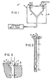
- Figure 1 is a cross-sectional view of a spiral/spider annular die 10 through which the molten thermoplastic ethylene polymer is extruded to form a single layer film, tube or pipe.
- Die block 12 contains channels 14 for directing the polymer to the die exit. As the molten thermoplastic ethylene polymer is extruded, it spreads out as it passes into the die channels 14.
- FIG. 2 which is a cross-section of a spiral die, there is indicated a spiral section J land entry section H and die land G.
- a die discharge outlet identified generally by reference numeral 16.
- the discharge outlet defines an exit die gap 18 which is formed by opposing surfaces of die lips 20 and 20'.
- the die lip 20 is offset from the outer edge of die lip 20' a distance X.
- X can be a distance of from .010 inch to .400 inch and preferably from .050 inch to .250 inch.
- the leading edge A of die lip 20' is offset from the leading edge B of the die lip 20.
- the leading edge defining the furthermost portion of groove 22 coincides with leading edge B.
- the distance W represents the effective die gap which can range from 0,015 to 0.125 inch whereas the letter Y represents the distance between the leading edge A and the furthermost inward distance of the die groove in line with said leading edge. Generally this distance can be from .030 inch to .250 inch preferably .050 inch to .125 inch.
- the groove preferably has a generally trapezoidal configuration (without base). Although other type configurations have some success such as semi-circular, curved, etc., it has been found that the trapezoidal configuration provides the best results.
- the length of the die groove can be from the leading edge B or slightly below the leading edge B to a point below the opposite leading edge 20'.
- extended die lip 20 is shown in connection with the outer surface, it will be understood that the extended die lip can be on the inner surface in which case the geometry of the die exit would be reversed.
- the present method is suitable for the formation of monolayer film although multilayer films can also be effectively processed.
- the films formed as disclosed herein may be extruded by tubular blown film extrusion process.
- a narrow molecular weight distribution polymer is melt extruded through an extruder.
- This extruder may have an extrusion screw therein with a length to diameter ratio of between 15:1 to 21:1, as described in U. S. Patent Application Serial No. 940,005, filed September 6, 1978, and refiled as Serial No. 064,399 on August 8, 1979, in the names of John C. Miller, et al, and entitled "A Process For Extruding Ethylene Polymers".
- This applic ation describes that this extrusion screw contains a feed, transition and metering section.
- the extrusion screw can contain a mixing section such as that described in U. S. Patents 3,486,192; 3,730,492 and 3,756,574, which are incorporated herein by reference.
- the mixing section is placed at the screw tip.
- the extruder which may be used herein may have a 18:1 to 32:1 length to internal diameter barrel ratio.
- the extrusion screw used in the present invention may have a length to diameter ratio of 15:1 to 32:1.
- the remaining space in the extrusion barrel can be partially filled with various types of plugs, torpedoes, or static mixers to reduce residence time of the polymer melt.
- the molten polymer is then extruded through a die, as will hereinafter be described.
- the polymer is extruded at a temperature of from 325° to 500°F.
- the polymer is extruded in an upward vertical direction in the form of a tube although it can be extruded downward or even sideways.
- the tubular film is expanded to the desired extent, cooled, or allowed to cool and flattened.
- The'tubular film is flattened by passing the film through a collapsing frame and a set of nip rolls. These nip rolls are driven, thereby providing means for withdrawing the tubular film away from the annular die.
- a positive pressure of gas for example; air or nitrogen, is maintained inside the tubular bubble.
- gas for example; air or nitrogen
- the pressure of the gas is controlled to give the desired degree of expansion to the tubular film.
- the degree of expansion as measured by the ratio of the fully expanded tube circumference to the circumference of the die annulus, is in the range 1/1 to 6/1 and preferably, 1/1 to 4/1.
- the tubular extrudate is cooled by conventional techniques such as, by air cooling, water quench or mandrel.
- Drawdown defined as the ratio of the die gap to the product of film gauge and blow up ratio, is kept greater than 2 to less than 250 and preferably greater than 25 to less than 15Q.
- Very thin gauge films can be produced at high drawdown from these polymers even when said polymer is highly contaminated with foreigh particles and/or gel.
- Thin gauge films of from 9.5 to 3.0 mils can be processed to exhibit ultimate elongations MD greater than from 4007. to 700% and TD greater than from 500x to 700%. Furthermore, these films are not perceived as "splitty”.
- Splitttiness is a qualitative term which describes.the notched tear response of a film at high deformation rates.
- Splitttiness reflects crack propagation rate. It is an end-use characteristic of certain types of film and is not well understood from a fundamentals perspective.
- the extrudate cools and its temperature falls below its melting point and it solidifies.
- the optical properties of the extrudate change as crystallization occurs and a frost line is formed.
- the position of this frost line above the annular die is a measure of the cooling rate of the film. This cooling rate has a very marked effect on the optical properties of the film produced herein.
- the ethylene polymer can also be extruded in the shape of a rod or other-solid cross section using the same die geometry for only the external surface. Additionally, the ethylene polymer can also be extruded into pipe through annular dies.
- the films formed as disclosed herein may also be extruded by slot cast film extrusion.
- This film extrusion method is veil known in the art and comprises extruding a sheet of molten polymer through a slot die and then quenching the extrudate using, for example, a chilled casting roll or water bath.
- film may be extruded horizontally and laid on top of the chill roll or it may be extruded downward and drawn under the chill roll.
- Extrudate cooling rates in the slot cast process are very high. Chill roll or water bath quenching is so fast that as the extrudate cools below its melting point, crystallites nucleate, very rapidly, supramolecular structures have little time.
- slot cast film is vastly improved over those characterizing films using the slow cooling rate, tubular blown film extrusion process.
- Compound temperatures in the slot cast film extrusion process generally run much higher than those typifying the tubular blown film process. Melt strength is not a process limitation in this film extrusion method. Both shear viscosity and extensional viscosity are lowered. Film can generally be extruded at higher output rate than practiced in.the blown film process. The higher temperatures reduce shear stresses in the die and raise the output threshold for melt fracture.
- the film produced by the method of the present invention has a thickness of greater than from 0.10 mils to 20 mils, preferably greater than from 0.10 to 10 mils, most preferably greater than from 0.10 to 4.0 mils.
- the 0.10 to 4.0 mil film is characterized by the following properties: a puncture resistance value of greater than about 7.0 in-lbs/mil; an ultimate elongation of greater than about 400%; a thermal shrinkage of less than 3% after heating to 105-110°C. and cooling to room temperature; tensile impact strength of greater than from 500 to " 2000 ft-lbs/in 3 and tensile strength greater than from 2000 to about 7000 psi.
- the polymers which may be used in the process of the present invention are linear homopolymers of ethylene or linear copolymers of a major mol percent ( 2 90%) of ethylene and a minor mol percent ( 1 10%) of one or more C 3 to C 8 alpha olefins.
- the C 3 to C 8 alpha olefins should not contain any branching on any of-their carbon atoms which is closer than the fourth carbon atom.
- the preferred C 3 to C 8 alpha olefins are propylene,butene-1, pentene-1, hexene-1, 4-methylpentene-1 and octene-1.
- the ethylene polymers have a melt flow ratio of from ⁇ 22 to ⁇ 32, and preferably of from ⁇ 25 to ⁇ 30.
- the melt flow ratio value is another means of indicating the molecular weight distribution of a polymer.
- the melt flow ratio (MFR) range of ⁇ 22 to ⁇ 32 thus corresponds to a Mw/Mn value range of from. 2.7 to 4.1.
- the homopolymers have a density of from 0.9 58 to ⁇ 0.972 and preferably of from ⁇ 0.961 to ⁇ 0.968.
- the copolymers have a density of from ⁇ 0.91 to ⁇ 0.96 and preferably ⁇ 0.917 to ⁇ 0.955, and most preferably, of from ⁇ 0.917 to ⁇ 0.935.
- the density of the copolymer, at a given melt index level for the copolymer is primarily regulated by the amount of the C 3 to C 8 comonomer which is copolymerized with the ethylene. In. the absence of the comonomer, the ethylene would homopoli- merize with the catalyst of the present invention to provide homopolymers having a density of about ⁇ 0.96.
- the addition of progressively larger amounts of the comonomers to the copolymers results in a progressive lowering of the density of the copolymer.
- the amount of each of the various C3 to C s comonomers needed to achieve the same result will vary from monomer to monomer, under the same reaction conditions.
- the melt index of a homopolymer or copolymer is a reflection of its molecular weight.
- Polymers having a relatively high molecular weight have relatively high viscosities and low melt index.
- Ultrahigh molecular weight ethylene polymers have a high load (HLMI) melt index of about 0.0 and a very high molecular weight,ethylene polymers have a high load melt index (HLMI) of from 0.0 to 1.0.
- the polymers of the present invention have a standard or normal load melt index of ⁇ 0.0 to 50, and preferably of from 0.5 to 35, and a high load melt index (HLMI) of from 11 to 950.
- the melt index of the polymers is a function of a combination of the polymerization temperature of the reaction, the density of the copolymer and the hydrogen/monomer ratio in the reaction system.
- the melt index is raised by increasing the polymerization temperature and/or by decreasing the density of the polymer and/or by increasing the hydrogen/monomer ratio.
- the ethylene polymers of the present invention have an unsaturated group content of ⁇ 1, and usually ⁇ 0.1 to ⁇ 0.3, C-C/1000 carbon atoms, and a cyclohexane extractables content of less than about 3, and preferably less than about 2, weight percent.
- This Example demonstrates the conventional procedures for extruding ethylene polymers into tubes.
- Example II demonstrates the use of an offset die without a groove.
- the resin used in Example I was passed through the same extrusion system of Example I.
- the die utilized was similar to Example I except that one of the die lips was offset by 0.050".
- the resin was extruded through the die at various rates up to 46 R.P.M. extruder screw speeds. Severe melt fracture was observed by visual observa- tion, although no effort was made to distinguish melt fracture levels on either side of the film.
- This Example demonstrates the substantially reduced melt fracture observed by utilizing the die having the offset and groove of the present invention.
- Example I The resin used in Example I was passed through the same extrusion system of Example I.
- the die was similar to Example I except for the differences as illustrated in Figs. I-III.
- the lip offset X was 0.050".
- the distance Y was 0.090 inch.
- Extruder speed was taken from low rates, below 34 R.P.M. to about 56 R.P.M. on the extruder. Very low levels of melt fracture were observed by the visual method at extruder sppeds up to 56 R.P.M. At 56 R.P.M. (running . about 25% higher than in previous examples) melt fracture was at a very low level.
Abstract
Description
- This invention relates to.a method for reducing melt fracture, particularly sharkskin melt fracture, during extrusion of a molten narrow molecular weight distribution, linear, ethylene copolymer, under conditions of flow rate and melt temperature which would otherwise produce such melt fracture.
- Conventional low density polyethylene has been historically polymerized in heavy walled autoclaves or tubular reactors at pressures as high as 50,000 psi and temperatures up to 300°C. The molecular structure of high pressure, low density polyethylene (HP-LDPE) is highly complex. The permutations in the arrangement of their simple building blocks are essentially infinite. HP-LDPE's are characterized by an intricate long chain branched molecular architecture. These long chain branches have a dramatic effect on the melt rheology of these resins. HP-LDPE's also possess a spectrum of short chain branches, generally 1 to 6 carbon atoms in length. These short chain branches disrupt crystal formation and depress resin density.
- More recently, low pressure technology has been provided whereby low density polyethylene can now be produced at low pressures and temperatures by copolymerizing ethylene with various alphaolefins. These low pressure LDPE (LP-LDPE) resins generally possess little, if any, long chain branching. They are short chain branched with branch length and frequency controlled by the type and amount of comonomer used_ during polymerization.
- U.S. Patent application Serial No. 892,325 filed March 3, 1978, and refiled as Serial No. 014,414 on February 27, 1979, in the names of F. J. Karol et al and entitled Preparation of Ethylene Copolymers In Fluid Bed Reactor, discloses that ethylene copolymers, having a density of 0.91 to 0.96, a melt flow ratio of ≥ 22 to ≤32 and a relatively low residual catalyst content can be produced in granular form, at relatively high productivities if. the monomer(s) are copolymerized in a gas phase process with a specific high activity Mg-Ti containing complex catalyst which is blended with an inert carrier material.
- U.S. patent application Serial No. 892,322 filed March 31, 1978, and refiled as Serial No. 012,720 on February 16, 1979, in the names of G. L. Goeke et al and entitled Impregnated Polymerization Catalyst, Process. For Preparing, and Use For Ethylene Copolymerization discloses that ethylene copolymers, having a density of 0.91 to 0.96, a melt flow ratio of ≥ 22 to ≤ 32 and a relatively low residual catalyst content can be produced in granular form, at relatively high productivities, if the monomer(s) are copolymerized in a gas phase process with a specific high-activity Mg-Ti-containing complex catalyst which is impregnated in a porous inert carrier material.
- U.S. patent application Serial No. 892,037 filed March 31, 1978, and refiled as Serial No. 014,412 on February 27, 1979, in the names of B. E. Wagner et al and entitled Polymerization Catalyst, Process For Preparing And Use For Ethylene Homopolymerization, discloses that ethylene homopolymers having a density of about ≥0.958 to ≤0.972 and a melt flow ratio of about ≥22 to about ≤32 which have a relatively low residual catalyst residue can be produced at relatively high productivities for commercial purposes by a low pressure gas phase process if the ethylene is homopolymerized. in the presence of a high-activity Mg-Ti-containing complex catalyst which is blended with an inert carrier material. The granular polymers thus produced are useful for a variety of end-use applications.
- The polymers as produced, for example, by the processes of said applications using the Mg-Ti containing complex catalyst possess a narrow molecular weight distribution, Mw/Mn, of about ≥ 2.7 to ≤ 4.1.
- Over the years, film extrusion equipment has been optimized for the rheology of HP-LDPE. The different molecular architecture of LP-LDPE results in a film processing behavior which requires different extrusion parameters. Although LP-LDPE resins can be extruded on equipment designed for HP-LDPE resins, certain equipment modifications are often required in order to extrude the low pressure resins at optimum conditions and at rates comparable to the high pressure resins. This is particularly true during extrusion of LP-LDPE which is processed into film. The problem appears to be that during extrusion of these particular resins, two aspects of rheological behavior play a significant role, i.e. shear and extension. Within a film extruder and extrusion die, a polymeric melt undergoes severe shearing deformation. As the extrusion screw pumps the melt to, and through, the film die, the melt experiences a wide range of shear rates. Host film extrusion processes are thought to expose the melt to shear at rates in the 100-5000 sec-1 range. Polymeric melts are known to exhibit what is commonly termed shear thinning behavior, i.e., non-Newtonian flow behavior. As shear rate is increased, viscosity (the ratio of shear stress, τ, to shear rate, γ) decreases. The degree of viscosity decrease depends upon the molecular weight, its distribution, and molecular configuration, i.e., long chain branching of the polymeric material. Short chain branching has little effect on shear viscosity. In general, high pressure low density polyethylenes have a broad molecular weight distribution and show enhanced shear thinning behavior in the shear rate range common to film extrusion. The narrow molecular
- weight distribution resins used in the present invention exhibit reduced shear thinning behavior at extrusion shear rates. The consequences of these differences are that the narrow distribution resins used in the present invention require higher power and develop higher pressures during extrusion than the high pressure low density polyethylene resins of broad molecular weight distribution and of equivalent average molecular weight.
- The rheology of polymeric materials is customarily studied in shear deformation. In simple shear the velocity gradient of the deforming resin is perpendicular to the flow direction. The mode of deformation is experimentally convenient but does not convey the essential information for understanding material response in film fabrication processes. As one can define a shear viscosity in terms of shear stress and shear rate, i.i.:
- η shear - τ12/γ̇
- where η shear = shear viscosity (poise)
- τ12 - shear stress (dynes/cm )
- γ̇ - shear rate (sec )
- η ext = π/ε̇
- η ext = extensional viscosity (poise)
- π= normal stress (dynes/cm2)
- ε̇= strain rate (sec-1)
- Due to the high shear stress developed during extrusion of a high molecular weight ethylene polymer having a narrow molecular weight distribution, melt fracture, particularly sharkskin melt fracture, occurs. Sharkskin melt fracture has been described in the literature for a number of polymers. "Sharkskin" is a term used to describe a particular type of surface irregularity which occurs during extrusion of some thermoplastic materials under certain conditions. It is characterized by a series of ridges perpendicular to the flow direction and is described by J.A. Brydson, Flow Properties of Polymer Melts, Van Nostrand-Reinhold Company (1970), pages 78-81.
- In the present process, the onset of sharkskin melt fracture is determined by visual observation of the surfaces of the film in its final form, i.e. after film winding. Specifically, this procedure for determining sharkskin melt fracture is as follows: The film is viewed and examined under a 20X magnification Nikon Profile Projector Model 6E using transmitted light.
- This observation shows a non-ridged surface (at no melt fracture) to a ridged surface under conditions of melt fracture. In another technique, the film can be held up to light and visually examined by the naked eye to determine the presence, severity or absence of melt fracture.
- The narrow molecular weight distribution ethylene polymers as described herein exhibit the characteristics of sharkskin melt fracture upon extruding using the prior art extrusion processes. These characteristics include a pattern of wave distortion perpendicular to the flow direction; occurrence at low extrusion rates (less than expected for elastic turbulance); not effected by the use of commonly employed metal die materials; and less melt fracture with increasing temperature.
- There are several known methods for eliminating sharkskin melt fracture in polymers. These methods include increasing the resin tesperature. However, in film formation this method is not commercially useful since increasing resin temperature generally causes lower rates of film formation, due to bubble instability or heat transfer limitations. Another method for eliminating sharkskin is described in U.S. Patent 3,920,782. In this method sharkskin formed during extrusion of polymeric materials is controlled or eliminated by cooling an outer layer of the material to close to the fusion temperature so that it emerges from the die with a reduced temperature while maintaining the bulk of the melt at the optimum working temperature. However, this method is difficult to employ and control.
- The invention of U.S. 3,920,782 is apparently based on the inventor's conclusions that the onset of sharkskin melt fracture under his operating conditions with his resins is a function, basically, of exceeding a critical linear velocity with his resins through his dies at his operating temperatures. In the process of the present invention, however, the onset of sharkskin melt fracture in the present applicants' resins under their operating conditions is a function, primarily, of exceeding a critical shear stress, and, to a lesser extent, a function of exceeding a critical linear. velocity.
- More recent,attempts have been made to reduce sharkskin melt fracture during extrusion of the particular ethylene polymers disclosed herein by geometric changes in the die. For example Application Serial No. 099,061 filed on December 12, 1979 and which is a continuation-in-part of Application Serial No. 001,932 filed January 8, 1979, discloses a method for reducing sharkskin melt fracture during extrusion of a molten narrow molecular weight distribution linear ethylene polymer by extruding the polymer through a die having a die gap greater than about 50 mils and wherein at least a portion of one surface of the die lip and/or die land in contact with the molten polymer is at an angle of divergence or convergence relative to 'the axis of flow of the molten polymer through the die. In addition, Application Serial No. 012,793 filed on February 16, 1979 discloses a process for forming blown tubular film essentially free of melt fracture by extruding the particular polymer through an extrusion die having a die gap of greater than about 50 mils and at a drawdown ratio of greater than about 2 to less than about 250.
- Finally, according to application Serial No. 192,701 filed on October 1, 1980 and which is assigned to a common assignee, sharkskin melt fracture is reduced by extruding polymer through a die having a discharge outlet defining an exit die gap formed by opposing die lip surfaces and wherein one surface of the die lip and/or die land in contact with the molten polymer extends beyond the opposing surface of the die lip and/or die land in the direction of the axis of flow of the molten polymer through the die exit whereby melt fracture is reduced on the surface of the polymer leaving the extended die lip surface.
- In the process of the present invention melt fracture, particularly sharkskin melt fracture, can be virtually eliminated on both surfaces of an extruded film formed from the polymers contemplated herein, by geometric changes in the die, i.e., by extruding the narrow molecular weight distribution . ethylene polymer, at normal film extrusion temperatures through a die having a discharge outlet defining an exit die gap and wherein one surface of the die lip and/or die land in contact with the molten polymer extends beyond the opposing surface of the die lip and/or die land in the direction of the axis of flow of the molten polymer through the die exit and wherein said extended die lip has a groove extending around said extended die lip, said groove being disposed opposite the surface of the opposing die lip and preferably opposite the leading edge of the opposing die lip surface, whereby melt fracture is reduced on both surfaces of the polymer leaving said die lip exit. The utility of the process of the present invention arises due to the fact that the stress field at the exit of the die determines the creation of sharkskin melt fracture. Thus, sharkskin melt fracture can be controlled or eliminated by the geometry at the exit of the die.
- Films suitable for packaging applications must possess a balance of key properties for broad end-use utility and wide commercial acceptance. These properties include film optical quality, for example, haze, gloss, and see-through characteristics. Mechanical strength properties such as puncture resistance, tensile strength, impact strength, stiffness, and tear resistance are important. Vapor transmission and gas permeability characteristics are important considerations in perishable goods packaging. Performance in film converting and packaging equipment is influenced by film properties such as coefficient of friction, blocking, heat sealability and flex resistance. Low density polyethylene has a wide range of utility such as in food packaging and non-food packaging applications.' Bags commonly produced from low density polyethylene include shipping sacks, textile bags, laundry and dry cleaning bags and trash bags. Low density polyethylene film can be used as drum liners for a number of liquid and solid chemicals and as protective wrap inside wooden crates. Low density polyethylene film can be used in a variety of agricultural and horticultural applications such as protecting plants and crops, as mulching, for storing of fruits and vegetables. Additionally, low density polyethylene film can be used in building applications such as a moisture or moisture vapor barrier. Further, low density polyethylene film can be coated and printed for use in newspapers, books, etc.
- Possessing a unique combination of the aforedescribed properties, high pressure low density polyethylene is the most important of the thermoplastic packaging films. It accounts for about 50% of the total usage of such films in packaging. Films made from the polymers of the present invention, preferably the ethylene hydrocarbon copolymers, offer an improved combination of end-use properties and are especially suited for many of the applications already served by high pressure low density polyethylene.
- An improvement in any one of the properties of a film such as elimination or reduction of sharkskin melt fracture or an improvement in the extrusion characteristics of the resin or an improvement in the film extrusion process itself is of the utmost importance regarding the acceptance of the film as a substitute for high pressure low density polyethylene in many end use applications.
- In the case where a single layer film is extruded consisting entirely of LP-LDPE resin, the reduction in melt fracture would occur on both surfaces of the film in contact with the die lips,
- In the accompanying drawings:-
- Figure 1 is a cut-away of a spiral/spider annular die for producing mono-layer film.
- Figure 2 shows a cross-section of the spiral die showing the offset configuration and the groove.
- Figure 3 is an enlarged view of the groove portion and die lips illustrated in Figure 2, and further includes film represented by dotted lines passing through the die.
- It has now been found that melt fracture, particularly sharkskin melt fracture formed during extrusion of a molten narrow molecular weight distribution, linear, ethylene polymer, at normal film extrusion temperature can be substantially eliminated or significantly reduced by extruding said polymer through a die having a discharge outlet defining an.exit die gap formed by opposing die lip surfaces and wherein one surface of the die lip and/or die land in contact with the molten polymer extends beyond the opposing surface of the die lip and/or die land in the direction of the axis of flow of the molten polymer through the die exit, said extended die lip having a groove extending around said extended die lip, said groove being disposed opposite the surface of the opposing die lips and preferably opposite the leading edge of the opposing die lip surfaces whereby melt fracture is reduced on the surface of the film leaving.the extended die lip surface. Dies
- The molten ethylene polymer is extruded through a die, preferably an annular die, having an extended die lip and a groove in the extended portion. The die which may be used in the present invention may be a spiral annular die, slit die, etc.
- Figure 1 is a cross-sectional view of a spiral/spider annular die 10 through which the molten thermoplastic ethylene polymer is extruded to form a single layer film, tube or pipe. Die
block 12 containschannels 14 for directing the polymer to the die exit. As the molten thermoplastic ethylene polymer is extruded, it spreads out as it passes into thedie channels 14. - Referring to Figure 2, which is a cross-section of a spiral die, there is indicated a spiral section J land entry section H and die land G. With reference to Figures 1 and 2, at the exit of the die, there is a die discharge outlet identified generally by
reference numeral 16. The discharge outlet defines anexit die gap 18 which is formed by opposing surfaces ofdie lips 20 and 20'. - As seen from Figure 3 the
die lip 20 is offset from the outer edge of die lip 20' a distance X. Generally X can be a distance of from .010 inch to .400 inch and preferably from .050 inch to .250 inch. Thus the leading edge A of die lip 20' is offset from the leading edge B of thedie lip 20. In the preferred embodiment, the leading edge defining the furthermost portion ofgroove 22 coincides with leading edge B. However, it will be understood that it need not coincide and that the leading edge defining the groove can be a slight distance away from leading edge B. - The distance W represents the effective die gap which can range from 0,015 to 0.125 inch whereas the letter Y represents the distance between the leading edge A and the furthermost inward distance of the die groove in line with said leading edge. Generally this distance can be from .030 inch to .250 inch preferably .050 inch to .125 inch. As best seen in Figures 2 and 3 the groove preferably has a generally trapezoidal configuration (without base). Although other type configurations have some success such as semi-circular, curved, etc., it has been found that the trapezoidal configuration provides the best results.
- The length of the die groove can be from the leading edge B or slightly below the leading edge B to a point below the opposite leading edge 20'.
- Although the
extended die lip 20 is shown in connection with the outer surface, it will be understood that the extended die lip can be on the inner surface in which case the geometry of the die exit would be reversed. - As mentioned previously, the present method is suitable for the formation of monolayer film although multilayer films can also be effectively processed.
- The films formed as disclosed herein may be extruded by tubular blown film extrusion process. In this process a narrow molecular weight distribution polymer is melt extruded through an extruder. This extruder may have an extrusion screw therein with a length to diameter ratio of between 15:1 to 21:1, as described in U. S. Patent Application Serial No. 940,005, filed September 6, 1978, and refiled as Serial No. 064,399 on August 8, 1979, in the names of John C. Miller, et al, and entitled "A Process For Extruding Ethylene Polymers". This applic ation describes that this extrusion screw contains a feed, transition and metering section. Optionally, the extrusion screw can contain a mixing section such as that described in U. S. Patents 3,486,192; 3,730,492 and 3,756,574, which are incorporated herein by reference. Preferably, the mixing section is placed at the screw tip.
- The extruder which may be used herein may have a 18:1 to 32:1 length to internal diameter barrel ratio. The extrusion screw used in the present invention may have a length to diameter ratio of 15:1 to 32:1. When, for example, an extrusion screw of a length to diameter ratio of 18/1 is used in a 24/1 extruder, the remaining space in the extrusion barrel can be partially filled with various types of plugs, torpedoes, or static mixers to reduce residence time of the polymer melt.
- The molten polymer is then extruded through a die, as will hereinafter be described.
- The polymer is extruded at a temperature of from 325° to 500°F. The polymer is extruded in an upward vertical direction in the form of a tube although it can be extruded downward or even sideways. After extrusion of the molten polymer through the annular die, the tubular film is expanded to the desired extent, cooled, or allowed to cool and flattened. The'tubular film is flattened by passing the film through a collapsing frame and a set of nip rolls. These nip rolls are driven, thereby providing means for withdrawing the tubular film away from the annular die.
- A positive pressure of gas, for example; air or nitrogen, is maintained inside the tubular bubble. As is known in the operation of conventional film processes, the pressure of the gas is controlled to give the desired degree of expansion to the tubular film. The degree of expansion, as measured by the ratio of the fully expanded tube circumference to the circumference of the die annulus, is in the range 1/1 to 6/1 and preferably, 1/1 to 4/1. The tubular extrudate is cooled by conventional techniques such as, by air cooling, water quench or mandrel.
- The drawdown characteristics of the polymers disclosed herein are excellent. Drawdown, defined as the ratio of the die gap to the product of film gauge and blow up ratio, is kept greater than 2 to less than 250 and preferably greater than 25 to less than 15Q. Very thin gauge films can be produced at high drawdown from these polymers even when said polymer is highly contaminated with foreigh particles and/or gel. Thin gauge films of from 9.5 to 3.0 mils can be processed to exhibit ultimate elongations MD greater than from 4007. to 700% and TD greater than from 500x to 700%. Furthermore, these films are not perceived as "splitty". "Splittiness" is a qualitative term which describes.the notched tear response of a film at high deformation rates. "Splittiness" reflects crack propagation rate. It is an end-use characteristic of certain types of film and is not well understood from a fundamentals perspective.
- As the polymer exits the annular die, the extrudate cools and its temperature falls below its melting point and it solidifies. The optical properties of the extrudate change as crystallization occurs and a frost line is formed. The position of this frost line above the annular die is a measure of the cooling rate of the film. This cooling rate has a very marked effect on the optical properties of the film produced herein.
- The ethylene polymer can also be extruded in the shape of a rod or other-solid cross section using the same die geometry for only the external surface. Additionally, the ethylene polymer can also be extruded into pipe through annular dies.
- The films formed as disclosed herein may also be extruded by slot cast film extrusion. This film extrusion method is veil known in the art and comprises extruding a sheet of molten polymer through a slot die and then quenching the extrudate using, for example, a chilled casting roll or water bath. In the chill roll process, film may be extruded horizontally and laid on top of the chill roll or it may be extruded downward and drawn under the chill roll. Extrudate cooling rates in the slot cast process are very high. Chill roll or water bath quenching is so fast that as the extrudate cools below its melting point, crystallites nucleate, very rapidly, supramolecular structures have little time. to grow and spherulites are held to a very small size. The optical properties of slot cast film are vastly improved over those characterizing films using the slow cooling rate, tubular blown film extrusion process. Compound temperatures in the slot cast film extrusion process generally run much higher than those typifying the tubular blown film process. Melt strength is not a process limitation in this film extrusion method. Both shear viscosity and extensional viscosity are lowered. Film can generally be extruded at higher output rate than practiced in.the blown film process. The higher temperatures reduce shear stresses in the die and raise the output threshold for melt fracture.
- The film produced by the method of the present invention has a thickness of greater than from 0.10 mils to 20 mils, preferably greater than from 0.10 to 10 mils, most preferably greater than from 0.10 to 4.0 mils. The 0.10 to 4.0 mil film is characterized by the following properties: a puncture resistance value of greater than about 7.0 in-lbs/mil; an ultimate elongation of greater than about 400%; a thermal shrinkage of less than 3% after heating to 105-110°C. and cooling to room temperature; tensile impact strength of greater than from 500 to " 2000 ft-lbs/in3 and tensile strength greater than from 2000 to about 7000 psi.
- Various conventional additives such as slip agents, antiblocking agents, and antioxidants can be incorporated in the film in accordance with conventional practice.
- The polymers which may be used in the process of the present invention are linear homopolymers of ethylene or linear copolymers of a major mol percent (2 90%) of ethylene and a minor mol percent (1 10%) of one or more C3 to C8 alpha olefins. The C3 to C8 alpha olefins should not contain any branching on any of-their carbon atoms which is closer than the fourth carbon atom. The preferred C3 to C8 alpha olefins are propylene,butene-1, pentene-1, hexene-1, 4-methylpentene-1 and octene-1.
- The ethylene polymers have a melt flow ratio of from ≥ 22 to ≤ 32, and preferably of from ≥ 25 to ≤ 30. The melt flow ratio value is another means of indicating the molecular weight distribution of a polymer. The melt flow ratio (MFR) range of ≥ 22 to ≤ 32 thus corresponds to a Mw/Mn value range of from. 2.7 to 4.1.
- The homopolymers have a density of from 0.958 to ≤ 0.972 and preferably of from ≥ 0.961 to ≤ 0.968.
- The copolymers have a density of from ≥ 0.91 to ≤ 0.96 and preferably ≥ 0.917 to ≤ 0.955, and most preferably, of from ≥ 0.917 to ≤ 0.935. The density of the copolymer, at a given melt index level for the copolymer, is primarily regulated by the amount of the C3 to C8 comonomer which is copolymerized with the ethylene. In. the absence of the comonomer, the ethylene would homopoli- merize with the catalyst of the present invention to provide homopolymers having a density of about ≥ 0.96. Thus, the addition of progressively larger amounts of the comonomers to the copolymers results in a progressive lowering of the density of the copolymer. The amount of each of the various C3 to Cs comonomers needed to achieve the same result will vary from monomer to monomer, under the same reaction conditions.
- Thus, to achieve the same results, in the copolymers, in terms of a given density, at a given melt index level, larger amounts of the different comonomers would be needed in the order of C3>C4>C5>C6>C7>C8.
- The melt index of a homopolymer or copolymer is a reflection of its molecular weight. Polymers having a relatively high molecular weight, have relatively high viscosities and low melt index. Ultrahigh molecular weight ethylene polymers have a high load (HLMI) melt index of about 0.0 and a very high molecular weight,ethylene polymers have a high load melt index (HLMI) of from 0.0 to 1.0. The polymers of the present invention have a standard or normal load melt index of ≥0.0 to 50, and preferably of from 0.5 to 35, and a high load melt index (HLMI) of from 11 to 950. The melt index of the polymers is a function of a combination of the polymerization temperature of the reaction, the density of the copolymer and the hydrogen/monomer ratio in the reaction system. Thus, the melt index is raised by increasing the polymerization temperature and/or by decreasing the density of the polymer and/or by increasing the hydrogen/monomer ratio.
- The ethylene polymers of the present invention have an unsaturated group content of < 1, and usually ≥ 0.1 to < 0.3, C-C/1000 carbon atoms, and a cyclohexane extractables content of less than about 3, and preferably less than about 2, weight percent.
- Having set forth the general nature of the invention, the following examples illustrate some specific embodiments of the invention. It is to be understood, however, that this invention is not limited to the examples, since the invention may be practiced the use of various modifications.
- This Example demonstrates the conventional procedures for extruding ethylene polymers into tubes.
- An ethylene-butcne copolymer which was prepared in accordance with the procedure of U.S. Patent application 852,325 filed March 31, 1978 in the names of F. J. Karol, et al, and which is available from Union Carbide Corporation under the Trademark designation Bakelite GRSN 7040 was formed into a tube using a 2-1/2 inch diameter extruder having a standard polyethylene screw with a Haddock mixing section. The copolymer had a density of .9197 gm/cc, and a melt index of 2.17 decigrams/min. The copolymer was formed into a tube which had a film thickness of 0.0015 inches by passing the resin through a conven- . tional 2-1/2" diameter screw extruder and into a conventional die having a die land length of 1-3/8", a 3.00 inch die diameter and a die gap of 0.040", . The sides of the die land were parallel with the flow axis of the polymer melt. There was no offset configuration, nor any grooves in the opposing die lip surface. The resin was extruded through the die at various rates utilizing extruder screw speeds in the range of 10 to 42 R.P.M. There was severe sharkskin melt fracture observed at all screw speeds, with the severity increasing with increasing screw speeds. The melt fracture was determined visually by holding the film against the light.
- This Example demonstrates the use of an offset die without a groove. The resin used in Example I was passed through the same extrusion system of Example I. The die utilized was similar to Example I except that one of the die lips was offset by 0.050". The resin was extruded through the die at various rates up to 46 R.P.M. extruder screw speeds. Severe melt fracture was observed by visual observa- tion, although no effort was made to distinguish melt fracture levels on either side of the film.
- This Example demonstrates the substantially reduced melt fracture observed by utilizing the die having the offset and groove of the present invention.
- The resin used in Example I was passed through the same extrusion system of Example I. The die was similar to Example I except for the differences as illustrated in Figs. I-III. Thus the lip offset X was 0.050". The distance Y was 0.090 inch. Extruder speed was taken from low rates, below 34 R.P.M. to about 56 R.P.M. on the extruder. Very low levels of melt fracture were observed by the visual method at extruder sppeds up to 56 R.P.M. At 56 R.P.M. (running . about 25% higher than in previous examples) melt fracture was at a very low level.
an extensional viscosity can be defined in terms of normal stress and strain rate, i.e.,:
Claims (13)
Applications Claiming Priority (2)
| Application Number | Priority Date | Filing Date | Title |
|---|---|---|---|
| US06/249,914 US4360494A (en) | 1981-04-01 | 1981-04-01 | Process for reducing melt fracture during extrusion of a molten narrow molecular weight distribution, linear, ethylene copolymer |
| US249914 | 1994-05-26 |
Publications (3)
| Publication Number | Publication Date |
|---|---|
| EP0061935A2 true EP0061935A2 (en) | 1982-10-06 |
| EP0061935A3 EP0061935A3 (en) | 1983-03-23 |
| EP0061935B1 EP0061935B1 (en) | 1985-08-21 |
Family
ID=22945553
Family Applications (1)
| Application Number | Title | Priority Date | Filing Date |
|---|---|---|---|
| EP82301705A Expired EP0061935B1 (en) | 1981-04-01 | 1982-03-31 | Process and apparatus for reducing melt fracture during extrusion of a molten narrow molecular weight distribution, linear, ethylene copolymer |
Country Status (12)
| Country | Link |
|---|---|
| US (1) | US4360494A (en) |
| EP (1) | EP0061935B1 (en) |
| JP (1) | JPS57201627A (en) |
| KR (1) | KR830008827A (en) |
| AU (1) | AU544475B2 (en) |
| BR (1) | BR8201846A (en) |
| CA (1) | CA1171218A (en) |
| DE (1) | DE3265536D1 (en) |
| DK (1) | DK146882A (en) |
| GR (1) | GR81398B (en) |
| NO (1) | NO821045L (en) |
| ZA (1) | ZA822239B (en) |
Cited By (1)
| Publication number | Priority date | Publication date | Assignee | Title |
|---|---|---|---|---|
| DE102007029310A1 (en) | 2007-02-13 | 2008-08-14 | Kiefel Extrusion Gmbh | Spiral distributor for a blown film plant |
Families Citing this family (23)
| Publication number | Priority date | Publication date | Assignee | Title |
|---|---|---|---|---|
| US4532189A (en) * | 1982-02-19 | 1985-07-30 | W. R. Grace & Co., Cryovac Div. | Linear polyethylene shrink films |
| US4525257A (en) * | 1982-12-27 | 1985-06-25 | Union Carbide Corporation | Low level irradiated linear low density ethylene/alpha-olefin copolymers and film extruded therefrom |
| US4554120A (en) * | 1983-06-28 | 1985-11-19 | Union Carbide Corporation | Process for eliminating surface melt fracture during extrusion of thermoplastic polymers |
| US4522776A (en) * | 1983-06-28 | 1985-06-11 | Union Carbide Corporation | Process for substantially eliminating surface melt fracture when extruding ethylene polymers |
| US4617241A (en) * | 1984-01-23 | 1986-10-14 | W. R. Grace & Co., Cryovac Div. | Linear polyethylene stretch/shrink films |
| US4832897A (en) * | 1984-02-07 | 1989-05-23 | Stamicarbon B.V. | Process for the preparation of blown film |
| US4551380A (en) * | 1984-05-10 | 1985-11-05 | W. R. Grace & Co., Cryovac Div. | Oriented heat-sealable multilayer packaging film |
| US4590124A (en) * | 1984-05-10 | 1986-05-20 | W. R. Grace & Co., Cryovac Div. | Storm window film |
| US4514465A (en) * | 1984-05-30 | 1985-04-30 | W. R. Grace & Co., Cryovac Div. | Storm window film comprising at least five layers |
| JPS61196070A (en) * | 1985-02-27 | 1986-08-30 | 大成建設株式会社 | Water stop method of structure |
| NL8502191A (en) * | 1985-08-06 | 1987-03-02 | Stamicarbon | METHOD FOR PRODUCING FLAT FILM. |
| US4713205A (en) * | 1985-09-25 | 1987-12-15 | Mobil Oil Corporation | Method for reducing melt fracture during extrusion of linear polyethylene homopolymers and copolymers by varying the geometry of the die exit face |
| US4671918A (en) * | 1985-10-25 | 1987-06-09 | National Distillers And Chemical Corporation | Apparatus and process for producing polyolefin film |
| US4753767A (en) * | 1986-04-03 | 1988-06-28 | The Dow Chemical Company | Extrusion apparatus and method |
| US4942010A (en) * | 1986-07-17 | 1990-07-17 | Wynn's-Precision, Inc. | Method of injection molding of tubular parts to eliminate weld lines |
| US4711602A (en) * | 1986-07-17 | 1987-12-08 | Precision Rubber Products Corporation | Turbulent flow gate for the injection molding of tubular parts, including parisons suitable for blow molding |
| US4780264A (en) * | 1987-05-22 | 1988-10-25 | The Dow Chemical Company | Linear low density polyethylene cast film |
| US4859398A (en) * | 1987-07-02 | 1989-08-22 | Mobil Oil Corporation | High shear extrusion of linear low density polyethylene |
| CN101346217B (en) * | 2005-12-26 | 2011-08-31 | 柯尼卡美能达精密光学株式会社 | Method of manufacturing cellulose film, manufacturing apparatus, optical film, polarizing plate and liquid crystal display |
| US20130319131A1 (en) | 2012-05-31 | 2013-12-05 | Chevron Phillips Chemical Company Lp | Controlling Melt Fracture in Bimodal Resin Pipe |
| JP6776860B2 (en) * | 2016-12-09 | 2020-10-28 | コニカミノルタ株式会社 | A sizing die, an extrusion molding device, and a method for manufacturing a tubular member using them. |
| SG11202112115XA (en) | 2019-05-30 | 2021-12-30 | Dow Global Technologies Llc | Method of extruding linear low-density polyethylene (lldpe) without surface fractures in the melt |
| CN110576580B (en) * | 2019-09-04 | 2024-04-16 | 深圳市特发信息光网科技股份有限公司 | Cable mould |
Citations (4)
| Publication number | Priority date | Publication date | Assignee | Title |
|---|---|---|---|---|
| US3876740A (en) * | 1972-10-27 | 1975-04-08 | Standard Oil Co | Process for improving interior surface smoothness and gloss in foamed tubular extrudates by the use of extrusion die faces of novel geometry |
| US3879158A (en) * | 1973-01-09 | 1975-04-22 | Enrique Schele | Apparatus for extruding thermoplastic annular shapes |
| US4021170A (en) * | 1975-05-21 | 1977-05-03 | Hoechst Aktiengesellschaft | Extruder with blow head |
| EP0051358A1 (en) * | 1980-10-01 | 1982-05-12 | Union Carbide Corporation | Method for reducing melt fracture during extrusion of a molten narrow molecular weight distribution, linear, ethylene copolymer |
Family Cites Families (13)
| Publication number | Priority date | Publication date | Assignee | Title |
|---|---|---|---|---|
| US3125620A (en) * | 1964-03-17 | Process for providing improved surface | ||
| US2813301A (en) * | 1954-12-13 | 1957-11-19 | Monsanto Chemicals | Sheeting die |
| US3038209A (en) * | 1958-07-10 | 1962-06-12 | Eastman Kodak Co | Method of dope-casting film at high shear rate |
| US3133313A (en) * | 1962-10-30 | 1964-05-19 | Nat Distillers Chem Corp | Extrusion die mechanism |
| CH479720A (en) * | 1968-03-02 | 1969-10-15 | Glanzstoff Ag | Device for producing elongated structures, in particular threads, thread bundles or ribbons |
| US3859017A (en) * | 1969-02-20 | 1975-01-07 | Rol | Extrusion of sheath onto elongated support using decompression zones |
| GB1441586A (en) * | 1972-07-12 | 1976-07-07 | Ici Ltd | Method for reducing sharkskin on extruded polymeric material |
| US3947214A (en) * | 1974-12-13 | 1976-03-30 | Corning Glass Works | Extrusion die mask |
| US3994654A (en) * | 1975-01-02 | 1976-11-30 | Monsanto Company | Die for extruding thermoplastic sheets |
| US4187269A (en) * | 1975-11-17 | 1980-02-05 | The Dow Chemical Company | Extrusion process for reducing melt fracture |
| US4243619A (en) * | 1978-03-31 | 1981-01-06 | Union Carbide Corporation | Process for making film from low density ethylene hydrocarbon copolymer |
| US4267146A (en) * | 1979-01-08 | 1981-05-12 | Union Carbide Corporation | Method for reducing melt fracture during extrusion of ethylene polymers |
| US4282177A (en) * | 1979-01-08 | 1981-08-04 | Union Carbide Corporation | Method for reducing sharkskin melt fracture during extrusion of ethylene polymers |
-
1981
- 1981-04-01 US US06/249,914 patent/US4360494A/en not_active Expired - Fee Related
-
1982
- 1982-03-29 NO NO821045A patent/NO821045L/en unknown
- 1982-03-30 GR GR67767A patent/GR81398B/el unknown
- 1982-03-31 CA CA000400102A patent/CA1171218A/en not_active Expired
- 1982-03-31 ZA ZA822239A patent/ZA822239B/en unknown
- 1982-03-31 DE DE8282301705T patent/DE3265536D1/en not_active Expired
- 1982-03-31 DK DK146882A patent/DK146882A/en not_active IP Right Cessation
- 1982-03-31 KR KR1019820001419A patent/KR830008827A/en unknown
- 1982-03-31 AU AU82228/82A patent/AU544475B2/en not_active Expired - Fee Related
- 1982-03-31 EP EP82301705A patent/EP0061935B1/en not_active Expired
- 1982-03-31 BR BR8201846A patent/BR8201846A/en unknown
- 1982-03-31 JP JP57051441A patent/JPS57201627A/en active Pending
Patent Citations (4)
| Publication number | Priority date | Publication date | Assignee | Title |
|---|---|---|---|---|
| US3876740A (en) * | 1972-10-27 | 1975-04-08 | Standard Oil Co | Process for improving interior surface smoothness and gloss in foamed tubular extrudates by the use of extrusion die faces of novel geometry |
| US3879158A (en) * | 1973-01-09 | 1975-04-22 | Enrique Schele | Apparatus for extruding thermoplastic annular shapes |
| US4021170A (en) * | 1975-05-21 | 1977-05-03 | Hoechst Aktiengesellschaft | Extruder with blow head |
| EP0051358A1 (en) * | 1980-10-01 | 1982-05-12 | Union Carbide Corporation | Method for reducing melt fracture during extrusion of a molten narrow molecular weight distribution, linear, ethylene copolymer |
Cited By (2)
| Publication number | Priority date | Publication date | Assignee | Title |
|---|---|---|---|---|
| DE102007029310A1 (en) | 2007-02-13 | 2008-08-14 | Kiefel Extrusion Gmbh | Spiral distributor for a blown film plant |
| EP1958756A1 (en) | 2007-02-13 | 2008-08-20 | Kiefel Extrusion Gmbh | Axial or cone spiral mandrel distributor for a blown film installation and method for manufacturing a multi-layered film |
Also Published As
| Publication number | Publication date |
|---|---|
| NO821045L (en) | 1982-10-04 |
| AU8222882A (en) | 1982-10-07 |
| ZA822239B (en) | 1983-02-23 |
| DK146882A (en) | 1982-10-02 |
| EP0061935A3 (en) | 1983-03-23 |
| GR81398B (en) | 1984-12-11 |
| BR8201846A (en) | 1983-03-01 |
| EP0061935B1 (en) | 1985-08-21 |
| US4360494A (en) | 1982-11-23 |
| JPS57201627A (en) | 1982-12-10 |
| AU544475B2 (en) | 1985-05-30 |
| CA1171218A (en) | 1984-07-24 |
| KR830008827A (en) | 1983-12-16 |
| DE3265536D1 (en) | 1985-09-26 |
Similar Documents
| Publication | Publication Date | Title |
|---|---|---|
| EP0051358B1 (en) | Method for reducing melt fracture during extrusion of a molten narrow molecular weight distribution, linear, ethylene copolymer | |
| US4360494A (en) | Process for reducing melt fracture during extrusion of a molten narrow molecular weight distribution, linear, ethylene copolymer | |
| US4339507A (en) | Linear low density ethylene hydrocarbon copolymer containing composition for extrusion coating | |
| US4486377A (en) | Process for reducing draw resonance in polymeric film | |
| US4948543A (en) | Process for eliminating surface melt fracture during extrusion of thermoplastic polymers | |
| US4282177A (en) | Method for reducing sharkskin melt fracture during extrusion of ethylene polymers | |
| US4552712A (en) | Process for reducing surface melt fracture during extrusion of ethylene polymers | |
| US4554120A (en) | Process for eliminating surface melt fracture during extrusion of thermoplastic polymers | |
| US4608221A (en) | Process for reducing draw resonance in polymeric film | |
| US4267146A (en) | Method for reducing melt fracture during extrusion of ethylene polymers | |
| US4522776A (en) | Process for substantially eliminating surface melt fracture when extruding ethylene polymers | |
| US6777520B2 (en) | High density polyethylene barrier grade resins and films, methods for making same | |
| KR970702897A (en) | MEDIUM MODULUS FILM COMPRISING SUBSTANTIALLY LINEAR POLYETHYLENE AND FABRICATION METHOD | |
| US5204032A (en) | Process for substantially eliminating surface melt fracture during extrusion of thermoplastic polymers | |
| EP0133213B1 (en) | Process for substantially eliminating surface melt fracture when extruding ethylene polymers | |
| US4713205A (en) | Method for reducing melt fracture during extrusion of linear polyethylene homopolymers and copolymers by varying the geometry of the die exit face | |
| EP2006070A1 (en) | Process for producing a polyethylene-polypropylene multilayer blown film | |
| EP0137120B1 (en) | Process for reducing surface melt fracture during extrusion of ethylene polymers | |
| EP0136412A1 (en) | Method for reducing surface melt fracture during extrusion of ethylene polymers | |
| EP0139089A2 (en) | Process for reducing vedge waver during formation of film from lldpe resins | |
| FI76955B (en) | FOERFARANDE FOER ATT MINSKA YTANS SMAELTFRAKTUR VID STRAENGSPRUTNING AV ETYLENPOLYMERER. | |
| JPH04290722A (en) | Polybutene pipe excellent in pressure-resistant strength and manufacture thereof |
Legal Events
| Date | Code | Title | Description |
|---|---|---|---|
| PUAI | Public reference made under article 153(3) epc to a published international application that has entered the european phase |
Free format text: ORIGINAL CODE: 0009012 |
|
| AK | Designated contracting states |
Designated state(s): BE DE FR GB IT NL SE |
|
| PUAL | Search report despatched |
Free format text: ORIGINAL CODE: 0009013 |
|
| AK | Designated contracting states |
Designated state(s): BE DE FR GB IT NL SE |
|
| 17P | Request for examination filed |
Effective date: 19830210 |
|
| ITF | It: translation for a ep patent filed |
Owner name: ING. C. GREGORJ S.P.A. |
|
| GRAA | (expected) grant |
Free format text: ORIGINAL CODE: 0009210 |
|
| AK | Designated contracting states |
Designated state(s): BE DE FR GB IT NL SE |
|
| PG25 | Lapsed in a contracting state [announced via postgrant information from national office to epo] |
Ref country code: NL Effective date: 19850821 Ref country code: FR Free format text: THE PATENT HAS BEEN ANNULLED BY A DECISION OF A NATIONAL AUTHORITY Effective date: 19850821 Ref country code: BE Effective date: 19850821 |
|
| PG25 | Lapsed in a contracting state [announced via postgrant information from national office to epo] |
Ref country code: SE Effective date: 19850830 |
|
| REF | Corresponds to: |
Ref document number: 3265536 Country of ref document: DE Date of ref document: 19850926 |
|
| NLV1 | Nl: lapsed or annulled due to failure to fulfill the requirements of art. 29p and 29m of the patents act | ||
| EN | Fr: translation not filed | ||
| PLBE | No opposition filed within time limit |
Free format text: ORIGINAL CODE: 0009261 |
|
| STAA | Information on the status of an ep patent application or granted ep patent |
Free format text: STATUS: NO OPPOSITION FILED WITHIN TIME LIMIT |
|
| 26N | No opposition filed | ||
| GBPC | Gb: european patent ceased through non-payment of renewal fee | ||
| PG25 | Lapsed in a contracting state [announced via postgrant information from national office to epo] |
Ref country code: DE Effective date: 19871201 |
|
| PG25 | Lapsed in a contracting state [announced via postgrant information from national office to epo] |
Ref country code: GB Effective date: 19881121 |
|
| EUG | Se: european patent has lapsed |
Ref document number: 82301705.8 Effective date: 19850816 |