EP0061908A2 - Improvements relating to fluid control or metering assemblies - Google Patents
Improvements relating to fluid control or metering assemblies Download PDFInfo
- Publication number
- EP0061908A2 EP0061908A2 EP82301596A EP82301596A EP0061908A2 EP 0061908 A2 EP0061908 A2 EP 0061908A2 EP 82301596 A EP82301596 A EP 82301596A EP 82301596 A EP82301596 A EP 82301596A EP 0061908 A2 EP0061908 A2 EP 0061908A2
- Authority
- EP
- European Patent Office
- Prior art keywords
- housing
- fluid control
- passage
- assembly according
- metering assembly
- Prior art date
- Legal status (The legal status is an assumption and is not a legal conclusion. Google has not performed a legal analysis and makes no representation as to the accuracy of the status listed.)
- Granted
Links
- 239000012530 fluid Substances 0.000 title claims description 14
- 230000000712 assembly Effects 0.000 title description 2
- 238000000429 assembly Methods 0.000 title description 2
- 239000004033 plastic Substances 0.000 claims description 7
- 229920003023 plastic Polymers 0.000 claims description 7
- 238000000465 moulding Methods 0.000 claims description 5
- 238000009428 plumbing Methods 0.000 claims description 3
- XLYOFNOQVPJJNP-UHFFFAOYSA-N water Substances O XLYOFNOQVPJJNP-UHFFFAOYSA-N 0.000 abstract description 19
- 239000002991 molded plastic Substances 0.000 abstract description 3
- 238000009434 installation Methods 0.000 description 3
- 239000000463 material Substances 0.000 description 2
- 238000007789 sealing Methods 0.000 description 2
- 229910001018 Cast iron Inorganic materials 0.000 description 1
- 238000010276 construction Methods 0.000 description 1
- 230000002093 peripheral effect Effects 0.000 description 1
- 230000003014 reinforcing effect Effects 0.000 description 1
- 238000011144 upstream manufacturing Methods 0.000 description 1
Images
Classifications
-
- G—PHYSICS
- G01—MEASURING; TESTING
- G01F—MEASURING VOLUME, VOLUME FLOW, MASS FLOW OR LIQUID LEVEL; METERING BY VOLUME
- G01F15/00—Details of, or accessories for, apparatus of groups G01F1/00 - G01F13/00 insofar as such details or appliances are not adapted to particular types of such apparatus
- G01F15/18—Supports or connecting means for meters
-
- Y—GENERAL TAGGING OF NEW TECHNOLOGICAL DEVELOPMENTS; GENERAL TAGGING OF CROSS-SECTIONAL TECHNOLOGIES SPANNING OVER SEVERAL SECTIONS OF THE IPC; TECHNICAL SUBJECTS COVERED BY FORMER USPC CROSS-REFERENCE ART COLLECTIONS [XRACs] AND DIGESTS
- Y10—TECHNICAL SUBJECTS COVERED BY FORMER USPC
- Y10T—TECHNICAL SUBJECTS COVERED BY FORMER US CLASSIFICATION
- Y10T137/00—Fluid handling
- Y10T137/5109—Convertible
-
- Y—GENERAL TAGGING OF NEW TECHNOLOGICAL DEVELOPMENTS; GENERAL TAGGING OF CROSS-SECTIONAL TECHNOLOGIES SPANNING OVER SEVERAL SECTIONS OF THE IPC; TECHNICAL SUBJECTS COVERED BY FORMER USPC CROSS-REFERENCE ART COLLECTIONS [XRACs] AND DIGESTS
- Y10—TECHNICAL SUBJECTS COVERED BY FORMER USPC
- Y10T—TECHNICAL SUBJECTS COVERED BY FORMER US CLASSIFICATION
- Y10T137/00—Fluid handling
- Y10T137/6851—With casing, support, protector or static constructional installations
- Y10T137/6966—Static constructional installations
- Y10T137/6991—Ground supporting enclosure
- Y10T137/6995—Valve and meter wells
- Y10T137/7021—Covers
-
- Y—GENERAL TAGGING OF NEW TECHNOLOGICAL DEVELOPMENTS; GENERAL TAGGING OF CROSS-SECTIONAL TECHNOLOGIES SPANNING OVER SEVERAL SECTIONS OF THE IPC; TECHNICAL SUBJECTS COVERED BY FORMER USPC CROSS-REFERENCE ART COLLECTIONS [XRACs] AND DIGESTS
- Y10—TECHNICAL SUBJECTS COVERED BY FORMER USPC
- Y10T—TECHNICAL SUBJECTS COVERED BY FORMER US CLASSIFICATION
- Y10T137/00—Fluid handling
- Y10T137/8593—Systems
- Y10T137/87917—Flow path with serial valves and/or closures
- Y10T137/88054—Direct response normally closed valve limits direction of flow
Definitions
- This invention relates to fluid control or metering assemblies. It is primarily intended for the installation of water meters and/or stopcocks in the main supply to a building.
- Such surface boxes are of heavy concrete construction. A large hole has to be dug and a base platform set at the bottom of it. The plumbing is brought over this base and the stopcock and meter, if provided, are fitted. The side walls are then built up around the inlet and outlet pipes, and completed usually by prefabricated rectangular frame members in concrete. The lid is normally of cast iron and split, for ease of opening.
- a fluid control or metering assembly comprising a top-lidded housing for burying upright in the ground with access through the top, inlet and outlet ports adapted to receive plumbing fittings for the external attachment of pipes, and a mounting for a fluid control or metering device, the mounting being such that when said device is fitted, a closed passage is formed via said device between said inlet and outlet ports.
- the fluid control device will be a stop cock carried by the mounting and operable through the top of the housing.
- the cock closure will be over a port in the base of the housing forming part of the passage.
- the passage may be adapted for metered or unmetered flow, the passage having a removable section which when in place completes an unmetered portion of the passage downstream of the stop cock, and which is replaceable by a meter whose engagement with the mounting ensures that flow is through said meter.
- the removable section may simply be a screw cap.
- a non-release valve is provided in the passage downstream of the removable section.
- the stop cock closed, the change from metered to unmetered flow can be made with no escape of water.
- the housing is preferably a unitary plastics moulding, and the mounting may have a main body which is a plastics moulding securable to the base of the housing by fastener means operable through the top of the housing.
- fastener means will conveniently be screws or bolts which can be tightened or loosened by a tool extending lengthwise into the housing, such as a screwdriver or box spanner.
- the housing can therefore be of very much smaller span than the conventional surface box. The fitting of the pipes to the outside of the box is done on installation and generally they do not need to be touched thereafter.
- the box comprises a main housing 1 which is of generally rectangular form with rounded corners in plan and tapering slightly outwardly from its base 2. It is moulded in hard plastics material. At the top it is stepped outwardly to provide a rim 3 with a circular screw-threaded opening 4 to receive a cover plate 5. When installed, the top of this will be flush with the surface of the ground. Although a seal could be provided for this cover, it need not be made watertight and any water that does penetrate may escape via holes in the shoulder 6 where the rim 3 steps inwardly to meet the main portion of the box. Reinforcing ribs 7 are provided to strengthen the rim 3. These are optional.
- fittings 8 and 9 for the external connection of water pipes. These communicate with ducts 10 and 11 which extend towards each other within generally triangular-shaped blocks 12 and 13 integral with the box moulding, and then turn upwards to open at the flat upper interior surface 14 of the base 2.
- bosses 15 with threaded holes to receive screws 16 which secure the stopcock assembly.
- earthing strip 17 of shallow U-form under the box, interconnecting the two fittings 8 and 9.
- the valve and meter housing has a main body 20, also moulded in hard plastics material, which in plan view (see Figures 5 and 6) is generally rectangular with rounded ends to fit closely into the bottom of the box. It has holes 21 along its straight sides which will register with the bosses 15. Its underside has a flat peripheral and central land area which seals against the surface 14, so that the duct 10 opens centrally into a cylindrical chamber 22 and the duct 11 opens centrally into a circular port 23. These may be surrounded by O-ring seals at the interface.
- the body 20 has a hollow upstanding spigot 24 integrally moulded with it in alignment with the centre of the chamber 22.
- a valve stem 25 of octagonal cross- section can move vertically with a close sliding fit in the base of this spigot, its upper end being screw-threaded to be engaged by the internal threading of a cylindrical sleeve 26 rotatable by a knob 27.
- the base of the valve stem has a head 28 with a washer 29 that will seal over the mouth of the duct 10.
- the washer will be rubber or soft plastics, while the other parts of this stopcock or valve can be hard moulded plastics.
- valve body is provided by the base 2 of the box and the body 20, and there are very simple moving parts which can be adjusted by turning the knob 27 by hand or an instrument inserted when the cover 5 is removed.
- the other end of the body 20 has a cylindrical recess 30 in its upper side with a raised'rim 31, externally screw-threaded.
- a cylindrical insert 32 fits closely within the recess 30, and is secured by screws 33. It has a semi-cylindrical opening 34-on the side nearest the stopcock, and a port 35 in the body 20 provides communication between the chamber 22 and this opening 34.
- On the other side a stepped cylindrical passage 36 is open at its lower end to the port 23. This passage houses a non-return valve 37, oriented to allow flow downwards into the duct 11.
- a sealing ring 38 is provided around the lower end of the passage 36 to cooperate with the body 20, and ensure that no water can seep directly from the opening 34 into the port 23.
- a cap 39 with a sealing ring is screwed over the rim 31 and completes a closed passage between the ducts 10 and 11, assuming the stopcock is open.
- the water flow is from the duct 10 into the chamber 20, through the port 35, up through the opening 34 and into the space immediately below the cap 39, down the passage 36 via the non-return valve 37, through the port 23 and into the duct 11.
- a water meter housing 40 can be seated within the rim 31, and it has an O-ring seal 41 to engage the top of the rim and different sized lugs 42 at opposite sides to fit corresponding recesses 43 and so ensure correct orientation.
- the underside of the meter housing has a crescent-shaped inlet 45, which mostly overlies the opening 34, and a circular outlet 46, surrounded by an O-ring seal 47, which registers with the passage 36.
- the seal 47 co-operates with the upper face of the insert 32.
- the top end face (not shown) of the housing 40 has the meter display.
- a frusto-conical cap 48 fits over the housing 40 and can be screwed on to the rim 31 to secure the housing in place. The top of the cap leaves the meter display exposed, while internally it engages the housing 40 and urges it down to compress the seals 41 and 47.
Landscapes
- Physics & Mathematics (AREA)
- Fluid Mechanics (AREA)
- General Physics & Mathematics (AREA)
- Measuring Volume Flow (AREA)
Abstract
Description
- This invention relates to fluid control or metering assemblies. It is primarily intended for the installation of water meters and/or stopcocks in the main supply to a building.
- Normally the water is brought to a building underground and there is an external stopcock to which access is by means of a box whose lid is flush with the ground surface. The cock is at the bottom of this and also, occasionally, a water meter. It is likely that such meters will be of increasing use.
- Generally such surface boxes are of heavy concrete construction. A large hole has to be dug and a base platform set at the bottom of it. The plumbing is brought over this base and the stopcock and meter, if provided, are fitted. The side walls are then built up around the inlet and outlet pipes, and completed usually by prefabricated rectangular frame members in concrete. The lid is normally of cast iron and split, for ease of opening.
- It is difficult to make such a structure waterproof. It is time-consuming to build, it has to be large to provide decent access to the fittings and to allow them to be undone for replacement or repair (a powerful spanner has to have freedom to move) and the transport and handling of the massive concrete blocks is added expense and trouble.
- It is the aim of this invention to provide a surface box which is easy to install and maintain, compact and light, and generally without most of the drawbacks outlined above.
- According to the present invention there is provided a fluid control or metering assembly comprising a top-lidded housing for burying upright in the ground with access through the top, inlet and outlet ports adapted to receive plumbing fittings for the external attachment of pipes, and a mounting for a fluid control or metering device, the mounting being such that when said device is fitted, a closed passage is formed via said device between said inlet and outlet ports.
- Although reference is made throughout this specification to a surface box for burying in the ground, it should be understood that it also applies to a box that can be recessed into a wall. Such a box will generally be shallower and simply turned on its side as compared with the surface box.
- Normally, the fluid control device will be a stop cock carried by the mounting and operable through the top of the housing. Preferably, the cock closure will be over a port in the base of the housing forming part of the passage. The passage may be adapted for metered or unmetered flow, the passage having a removable section which when in place completes an unmetered portion of the passage downstream of the stop cock, and which is replaceable by a meter whose engagement with the mounting ensures that flow is through said meter. The removable section may simply be a screw cap.
- Conveniently, a non-release valve is provided in the passage downstream of the removable section. Thus with the stop cock closed, the change from metered to unmetered flow can be made with no escape of water. There could instead be another stop cock, similar to the upstream one.
- The housing is preferably a unitary plastics moulding, and the mounting may have a main body which is a plastics moulding securable to the base of the housing by fastener means operable through the top of the housing. These fasteners will conveniently be screws or bolts which can be tightened or loosened by a tool extending lengthwise into the housing, such as a screwdriver or box spanner. The housing can therefore be of very much smaller span than the conventional surface box. The fitting of the pipes to the outside of the box is done on installation and generally they do not need to be touched thereafter.
- For a better understanding of the invention one constructional form will now be described, by way of example, with reference to the accompanying drawings, in which:
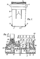
- Figure 1 is a side elevation of a surface box for a stop cock and water meter,
- Figure 2 is a vertical section, to an enlarged scale, of the lower portion of the box,
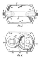
- Figure 3 is an underneath plan view of the box,
- Figure 4 is a top plan view of a stop cock assembly housed in the base of the box,
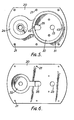
- Figure 5 is a top plan view of the main body of the assembly,
- Figure 6 is an underneath plan view of the body of Figure 5,
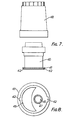
- Figure 7 is an exploded side elevation of a water meter housing and cap in vertical alignment for fitting to the stop cock assembly, and
- Figure 8 is an underneath plan view of the meter housing.
- The box comprises a main housing 1 which is of generally rectangular form with rounded corners in plan and tapering slightly outwardly from its
base 2. It is moulded in hard plastics material. At the top it is stepped outwardly to provide a rim 3 with a circular screw-threaded opening 4 to receive a cover plate 5. When installed, the top of this will be flush with the surface of the ground. Although a seal could be provided for this cover, it need not be made watertight and any water that does penetrate may escape via holes in theshoulder 6 where the rim 3 steps inwardly to meet the main portion of the box. Reinforcingribs 7 are provided to strengthen the rim 3. These are optional. - At the opposite ends of the
base 2 there arefittings ducts shaped blocks upper interior surface 14 of thebase 2. Along the two longer edges in the recessed underside of the base there arebosses 15 with threaded holes to receivescrews 16 which secure the stopcock assembly. There is also anearthing strip 17 of shallow U-form under the box, interconnecting the twofittings - The valve and meter housing has a
main body 20, also moulded in hard plastics material, which in plan view (see Figures 5 and 6) is generally rectangular with rounded ends to fit closely into the bottom of the box. It hasholes 21 along its straight sides which will register with thebosses 15. Its underside has a flat peripheral and central land area which seals against thesurface 14, so that theduct 10 opens centrally into acylindrical chamber 22 and theduct 11 opens centrally into acircular port 23. These may be surrounded by O-ring seals at the interface. - The
body 20 has a hollowupstanding spigot 24 integrally moulded with it in alignment with the centre of thechamber 22. Avalve stem 25 of octagonal cross- section can move vertically with a close sliding fit in the base of this spigot, its upper end being screw-threaded to be engaged by the internal threading of acylindrical sleeve 26 rotatable by aknob 27. The base of the valve stem has ahead 28 with awasher 29 that will seal over the mouth of theduct 10. The washer will be rubber or soft plastics, while the other parts of this stopcock or valve can be hard moulded plastics. - Thus the valve body is provided by the
base 2 of the box and thebody 20, and there are very simple moving parts which can be adjusted by turning theknob 27 by hand or an instrument inserted when the cover 5 is removed. - The other end of the
body 20 has acylindrical recess 30 in its upper side with a raised'rim 31, externally screw-threaded. Acylindrical insert 32 fits closely within therecess 30, and is secured byscrews 33. It has a semi-cylindrical opening 34-on the side nearest the stopcock, and aport 35 in thebody 20 provides communication between thechamber 22 and this opening 34. On the other side a steppedcylindrical passage 36 is open at its lower end to theport 23. This passage houses anon-return valve 37, oriented to allow flow downwards into theduct 11. Asealing ring 38 is provided around the lower end of thepassage 36 to cooperate with thebody 20, and ensure that no water can seep directly from theopening 34 into theport 23. - In one mode of operation, without a water meter, a
cap 39 with a sealing ring is screwed over therim 31 and completes a closed passage between theducts duct 10 into thechamber 20, through theport 35, up through theopening 34 and into the space immediately below thecap 39, down thepassage 36 via thenon-return valve 37, through theport 23 and into theduct 11. - When a water meter is to be fitted, the stopcock is closed down, and the
cap 39 removed. Water cannot flow back from theduct 11 because of thenon-return valve 37. The circular base of awater meter housing 40 can be seated within therim 31, and it has an O-ring seal 41 to engage the top of the rim and differentsized lugs 42 at opposite sides to fit correspondingrecesses 43 and so ensure correct orientation. - As seen in Figure 8, the underside of the meter housing has a crescent-shaped
inlet 45, which mostly overlies theopening 34, and acircular outlet 46, surrounded by an O-ring seal 47, which registers with thepassage 36. Theseal 47 co-operates with the upper face of theinsert 32. The top end face (not shown) of thehousing 40 has the meter display. A frusto-conical cap 48 fits over thehousing 40 and can be screwed on to therim 31 to secure the housing in place. The top of the cap leaves the meter display exposed, while internally it engages thehousing 40 and urges it down to compress theseals - The path for the water from the
opening 34 is now up into the meter housing throughinlet 45, and then down throughoutlet 46 past thenon-return valve 37. The passage of water is thus recorded. - For installation of this box a fairly small hole has to be dug but with room either side to provide external access to the fittings at the inlet and outlet ports. Once the pipes have been fitted to these it is unlikely that they will have to receive any attention. Although the box is of small plan area, the meter is readily accessible and can be read through the top of the
cap 48.
Claims (8)
Priority Applications (1)
| Application Number | Priority Date | Filing Date | Title |
|---|---|---|---|
| AT82301596T ATE21554T1 (en) | 1981-03-27 | 1982-03-26 | ARRANGEMENTS FOR CONTROLLING AND MEASURING LIQUIDS. |
Applications Claiming Priority (6)
| Application Number | Priority Date | Filing Date | Title |
|---|---|---|---|
| GB8109620 | 1981-03-27 | ||
| GB8109620 | 1981-03-27 | ||
| GB8111450 | 1981-04-11 | ||
| GB8111450 | 1981-04-11 | ||
| GB8125720 | 1981-08-22 | ||
| GB8125720 | 1981-08-22 |
Publications (3)
| Publication Number | Publication Date |
|---|---|
| EP0061908A2 true EP0061908A2 (en) | 1982-10-06 |
| EP0061908A3 EP0061908A3 (en) | 1983-08-24 |
| EP0061908B1 EP0061908B1 (en) | 1986-08-20 |
Family
ID=27261149
Family Applications (1)
| Application Number | Title | Priority Date | Filing Date |
|---|---|---|---|
| EP19820301596 Expired EP0061908B1 (en) | 1981-03-27 | 1982-03-26 | Improvements relating to fluid control or metering assemblies |
Country Status (3)
| Country | Link |
|---|---|
| US (1) | US4665941A (en) |
| EP (1) | EP0061908B1 (en) |
| DE (1) | DE3272672D1 (en) |
Cited By (13)
| Publication number | Priority date | Publication date | Assignee | Title |
|---|---|---|---|---|
| EP0125010A3 (en) * | 1983-04-05 | 1985-10-30 | David Rosser Hudson | Improvements relating to fluid control and/or metering assemblies |
| FR2585387A2 (en) * | 1985-07-26 | 1987-01-30 | Bonnet Jean Claude | EQUIPMENT TERMINAL AUTHORIZING REMOTE READING OF WATER CONSUMPTION ON COUNTERS |
| GB2192996A (en) * | 1986-07-21 | 1988-01-27 | Wigley Albert F | Flow meter installations |
| EP0327972A1 (en) * | 1988-02-09 | 1989-08-16 | Glynwed Tubes & Fittings Limited | Improvements in or relating to valves |
| EP0317061A3 (en) * | 1987-09-29 | 1991-05-02 | Gerald John Evans | Water metering assembly |
| GB2246443A (en) * | 1990-07-20 | 1992-01-29 | Foraquest Ltd | Below ground water metering assembly |
| WO1992004567A1 (en) * | 1990-08-30 | 1992-03-19 | George Stack | Water meter assemblies |
| WO1993004309A1 (en) * | 1991-08-23 | 1993-03-04 | Trevor Thomas Esplin | Coupling and control arrangement for a fluid metering device |
| AU645740B3 (en) * | 1990-08-30 | 1994-01-20 | G.S. Technology Pty Ltd | Water meter assemblies |
| GB2284900A (en) * | 1993-11-11 | 1995-06-21 | Atlantic Plastics Ltd | Water meter housing |
| AU662284B3 (en) * | 1990-08-30 | 1995-08-24 | G.S. Technology Pty Ltd | Water meter assemblies |
| AU780782B2 (en) * | 1990-08-30 | 2005-04-14 | G.S. Technology Pty Ltd | Water meter assemblies |
| US10689834B2 (en) | 2017-03-06 | 2020-06-23 | Bingham & Taylor Corp. | Meter pit and method of manufacturing the same |
Families Citing this family (6)
| Publication number | Priority date | Publication date | Assignee | Title |
|---|---|---|---|---|
| GR870129B (en) * | 1987-01-27 | 1987-02-04 | Giatzidis Ippokratis | Stable bicarbonate - glycylglycine dialysate for hemodialysis and peritoneal dialysis |
| SE456830B (en) * | 1987-03-17 | 1988-11-07 | Anders Westerberg | SET TO PREVENT FREEZING IN PIPES WITH BACK VALVE AND SAFETY VALVE AND PIPE MANAGEMENT SYSTEM BEFORE IMPLEMENTING THE SET |
| DE19708920B4 (en) * | 1997-03-05 | 2009-04-16 | Minol International Gmbh & Co. Kg | Concealed fitting |
| CN101726340B (en) * | 2009-12-21 | 2011-02-16 | 浙江世进水控股份有限公司 | Check valve special for water meter |
| US10746406B2 (en) | 2018-09-18 | 2020-08-18 | Georg Fischer Central Plastics Llc | Breaker box assembly |
| US11473957B2 (en) | 2020-01-02 | 2022-10-18 | Georg Fischer Central Plastics Llc | Meter bypass assembly having a housing including valve bodies rotationally fixed to opposing ends of a shaft |
Family Cites Families (10)
| Publication number | Priority date | Publication date | Assignee | Title |
|---|---|---|---|---|
| US1249435A (en) * | 1916-10-31 | 1917-12-11 | Herbert M Lofton | Meter-box. |
| US2529254A (en) * | 1947-02-24 | 1950-11-07 | Kieley & Mueller | Controller |
| US2619837A (en) * | 1951-03-16 | 1952-12-02 | Ford Meter Box Company Inc | Meter box and meter mounting |
| US3834417A (en) * | 1972-04-10 | 1974-09-10 | Norgren Co C A | Coupling unit for fluid control components |
| US3894432A (en) * | 1973-12-20 | 1975-07-15 | Donald W Coughlin | Combination metered water service installation unit |
| US3913400A (en) * | 1974-04-10 | 1975-10-21 | Mueller Co | Plastic meter box |
| DE2442482C3 (en) * | 1974-09-05 | 1978-10-26 | Hans Grohe Gmbh & Co Kg, 7622 Schiltach | Valve arrangement for controlling the water supply to one or more water dispensing points |
| US4076040A (en) * | 1976-06-01 | 1978-02-28 | Hancor, Inc. | Alternator valve |
| FR2399648A1 (en) * | 1977-08-05 | 1979-03-02 | Ligier Automobiles | Inspection cover for water meter - comprises one-piece moulded container with lip supporting internal shelf, and removable cover |
| US4257446A (en) * | 1979-05-29 | 1981-03-24 | Ray Charles W | Fluid flow shut-off system |
-
1982
- 1982-03-26 EP EP19820301596 patent/EP0061908B1/en not_active Expired
- 1982-03-26 US US06/362,420 patent/US4665941A/en not_active Expired - Fee Related
- 1982-03-26 DE DE8282301596T patent/DE3272672D1/en not_active Expired
Cited By (18)
| Publication number | Priority date | Publication date | Assignee | Title |
|---|---|---|---|---|
| EP0125010A3 (en) * | 1983-04-05 | 1985-10-30 | David Rosser Hudson | Improvements relating to fluid control and/or metering assemblies |
| FR2585387A2 (en) * | 1985-07-26 | 1987-01-30 | Bonnet Jean Claude | EQUIPMENT TERMINAL AUTHORIZING REMOTE READING OF WATER CONSUMPTION ON COUNTERS |
| EP0210933A3 (en) * | 1985-07-26 | 1988-01-07 | Jean-Claude Bonnet | Equipment pole for the remote reading of water consumption |
| GB2192996A (en) * | 1986-07-21 | 1988-01-27 | Wigley Albert F | Flow meter installations |
| EP0317061A3 (en) * | 1987-09-29 | 1991-05-02 | Gerald John Evans | Water metering assembly |
| EP0327972A1 (en) * | 1988-02-09 | 1989-08-16 | Glynwed Tubes & Fittings Limited | Improvements in or relating to valves |
| AU621340B2 (en) * | 1988-02-09 | 1992-03-12 | Glynwed Tubes & Fittings Limited | Improvements in or relating to valves |
| GB2246443B (en) * | 1990-07-20 | 1994-12-14 | Foraquest Ltd | Improvement relating to waterflow meters |
| GB2246443A (en) * | 1990-07-20 | 1992-01-29 | Foraquest Ltd | Below ground water metering assembly |
| WO1992004567A1 (en) * | 1990-08-30 | 1992-03-19 | George Stack | Water meter assemblies |
| AU645740B3 (en) * | 1990-08-30 | 1994-01-20 | G.S. Technology Pty Ltd | Water meter assemblies |
| AU662284B3 (en) * | 1990-08-30 | 1995-08-24 | G.S. Technology Pty Ltd | Water meter assemblies |
| AU780782B2 (en) * | 1990-08-30 | 2005-04-14 | G.S. Technology Pty Ltd | Water meter assemblies |
| WO1993004309A1 (en) * | 1991-08-23 | 1993-03-04 | Trevor Thomas Esplin | Coupling and control arrangement for a fluid metering device |
| GB2284900A (en) * | 1993-11-11 | 1995-06-21 | Atlantic Plastics Ltd | Water meter housing |
| GB2284900B (en) * | 1993-11-11 | 1997-10-29 | Atlantic Plastics Ltd | Improvements relating to water meter housings |
| US10689834B2 (en) | 2017-03-06 | 2020-06-23 | Bingham & Taylor Corp. | Meter pit and method of manufacturing the same |
| US12188211B2 (en) | 2017-03-06 | 2025-01-07 | Bingham & Taylor Corp. | Meter pit and method of manufacturing the same |
Also Published As
| Publication number | Publication date |
|---|---|
| DE3272672D1 (en) | 1986-09-25 |
| EP0061908B1 (en) | 1986-08-20 |
| US4665941A (en) | 1987-05-19 |
| EP0061908A3 (en) | 1983-08-24 |
Similar Documents
| Publication | Publication Date | Title |
|---|---|---|
| US4665941A (en) | Fluid control of metering assemblies | |
| EP0248079B1 (en) | Faucet valve with anti-siphon back flow preventer | |
| US8302220B2 (en) | Method and apparatus for assembling and sealing bathtub overflow and waste water ports | |
| US10329752B2 (en) | Overflow assembly for bathtubs and the like | |
| US6173459B1 (en) | Control for a bathtub waste water drain | |
| EP0950768A2 (en) | Putty plates | |
| US4805661A (en) | Faucet valve with anti-siphon back flow preventer | |
| EP0950843A2 (en) | Water valves for faucet fittings | |
| US4036249A (en) | Diverter valve | |
| US5983918A (en) | Balancing valve assembly of a cold and hot water mixing valve | |
| US4979539A (en) | Sanitary mixing valve | |
| GB2233100A (en) | Water metering assembly | |
| EP0105758A1 (en) | Fluid control assembly | |
| EP0115407A2 (en) | Combined stop-cock chamber and surface box | |
| JPH0152529B2 (en) | ||
| US3431938A (en) | Surface mount mixing valve | |
| JP3764571B2 (en) | Water faucet box | |
| AU2019250122B2 (en) | Modular valve and hydrant covers | |
| US4413532A (en) | Orifice meter with isolation valve on the carrier | |
| JP3022789B2 (en) | Flow measurement stopcock | |
| KR920001149Y1 (en) | Device for connecting gauge meter | |
| JP2001021404A (en) | Water meter | |
| KR102492703B1 (en) | large water matter for preventing rigging and rotating | |
| JPS624576Y2 (en) | ||
| KR0126489Y1 (en) | Anti-freezing valve |
Legal Events
| Date | Code | Title | Description |
|---|---|---|---|
| PUAI | Public reference made under article 153(3) epc to a published international application that has entered the european phase |
Free format text: ORIGINAL CODE: 0009012 |
|
| AK | Designated contracting states |
Designated state(s): AT BE CH DE FR GB IT LU NL SE |
|
| PUAL | Search report despatched |
Free format text: ORIGINAL CODE: 0009013 |
|
| AK | Designated contracting states |
Designated state(s): AT BE CH DE FR GB IT LI LU NL SE |
|
| 17P | Request for examination filed |
Effective date: 19840206 |
|
| RAP1 | Party data changed (applicant data changed or rights of an application transferred) |
Owner name: HUDSON, DAVID ROSSER |
|
| GRAA | (expected) grant |
Free format text: ORIGINAL CODE: 0009210 |
|
| AK | Designated contracting states |
Kind code of ref document: B1 Designated state(s): AT BE CH DE FR GB IT LI LU NL SE |
|
| REF | Corresponds to: |
Ref document number: 21554 Country of ref document: AT Date of ref document: 19860915 Kind code of ref document: T |
|
| REF | Corresponds to: |
Ref document number: 3272672 Country of ref document: DE Date of ref document: 19860925 |
|
| ITF | It: translation for a ep patent filed | ||
| ET | Fr: translation filed | ||
| PG25 | Lapsed in a contracting state [announced via postgrant information from national office to epo] |
Ref country code: LU Free format text: LAPSE BECAUSE OF NON-PAYMENT OF DUE FEES Effective date: 19870331 |
|
| PLBI | Opposition filed |
Free format text: ORIGINAL CODE: 0009260 |
|
| 26 | Opposition filed |
Opponent name: WATERFIT LIMITED Effective date: 19870519 |
|
| NLR1 | Nl: opposition has been filed with the epo |
Opponent name: WATERFIT LIMITED |
|
| REG | Reference to a national code |
Ref country code: GB Ref legal event code: 732 |
|
| PG25 | Lapsed in a contracting state [announced via postgrant information from national office to epo] |
Ref country code: AT Effective date: 19890326 |
|
| PG25 | Lapsed in a contracting state [announced via postgrant information from national office to epo] |
Ref country code: SE Effective date: 19890327 |
|
| PGFP | Annual fee paid to national office [announced via postgrant information from national office to epo] |
Ref country code: FR Payment date: 19890329 Year of fee payment: 8 |
|
| ITTA | It: last paid annual fee | ||
| PG25 | Lapsed in a contracting state [announced via postgrant information from national office to epo] |
Ref country code: LI Free format text: LAPSE BECAUSE OF NON-PAYMENT OF DUE FEES Effective date: 19890331 Ref country code: CH Free format text: LAPSE BECAUSE OF NON-PAYMENT OF DUE FEES Effective date: 19890331 |
|
| PGFP | Annual fee paid to national office [announced via postgrant information from national office to epo] |
Ref country code: NL Payment date: 19890331 Year of fee payment: 8 Ref country code: GB Payment date: 19890331 Year of fee payment: 8 |
|
| PGFP | Annual fee paid to national office [announced via postgrant information from national office to epo] |
Ref country code: BE Payment date: 19890419 Year of fee payment: 8 |
|
| PGFP | Annual fee paid to national office [announced via postgrant information from national office to epo] |
Ref country code: DE Payment date: 19890529 Year of fee payment: 8 |
|
| REG | Reference to a national code |
Ref country code: CH Ref legal event code: PL |
|
| RDAG | Patent revoked |
Free format text: ORIGINAL CODE: 0009271 |
|
| STAA | Information on the status of an ep patent application or granted ep patent |
Free format text: STATUS: PATENT REVOKED |
|
| 27W | Patent revoked |
Effective date: 19900313 |
|
| GBPR | Gb: patent revoked under art. 102 of the ep convention designating the uk as contracting state | ||
| BERE | Be: lapsed |
Owner name: HUDSON DAVID ROSSER Effective date: 19900331 |
|
| NLR2 | Nl: decision of opposition | ||
| EUG | Se: european patent has lapsed |
Ref document number: 82301596.1 Effective date: 19891016 |