EP0061796A1 - Electric device comprising at least one low-pressure mercury vapour discharge tube - Google Patents
Electric device comprising at least one low-pressure mercury vapour discharge tube Download PDFInfo
- Publication number
- EP0061796A1 EP0061796A1 EP82200297A EP82200297A EP0061796A1 EP 0061796 A1 EP0061796 A1 EP 0061796A1 EP 82200297 A EP82200297 A EP 82200297A EP 82200297 A EP82200297 A EP 82200297A EP 0061796 A1 EP0061796 A1 EP 0061796A1
- Authority
- EP
- European Patent Office
- Prior art keywords
- discharge tube
- voltage
- low
- mercury vapour
- electric device
- Prior art date
- Legal status (The legal status is an assumption and is not a legal conclusion. Google has not performed a legal analysis and makes no representation as to the accuracy of the status listed.)
- Granted
Links
- 229910052753 mercury Inorganic materials 0.000 title claims abstract description 48
- QSHDDOUJBYECFT-UHFFFAOYSA-N mercury Chemical compound [Hg] QSHDDOUJBYECFT-UHFFFAOYSA-N 0.000 title claims abstract description 45
- 239000003990 capacitor Substances 0.000 claims description 29
- 229910052743 krypton Inorganic materials 0.000 claims description 3
- DNNSSWSSYDEUBZ-UHFFFAOYSA-N krypton atom Chemical compound [Kr] DNNSSWSSYDEUBZ-UHFFFAOYSA-N 0.000 claims description 3
- 239000007858 starting material Substances 0.000 description 12
- 239000007789 gas Substances 0.000 description 5
- XKRFYHLGVUSROY-UHFFFAOYSA-N Argon Chemical compound [Ar] XKRFYHLGVUSROY-UHFFFAOYSA-N 0.000 description 2
- 239000000945 filler Substances 0.000 description 2
- 239000000203 mixture Substances 0.000 description 2
- 238000010079 rubber tapping Methods 0.000 description 2
- 238000004804 winding Methods 0.000 description 2
- 229910000497 Amalgam Inorganic materials 0.000 description 1
- 101100490767 Mus musculus Aldh1a1 gene Proteins 0.000 description 1
- XUIMIQQOPSSXEZ-UHFFFAOYSA-N Silicon Chemical compound [Si] XUIMIQQOPSSXEZ-UHFFFAOYSA-N 0.000 description 1
- 229910052786 argon Inorganic materials 0.000 description 1
- 230000002457 bidirectional effect Effects 0.000 description 1
- 230000002146 bilateral effect Effects 0.000 description 1
- 238000006243 chemical reaction Methods 0.000 description 1
- 230000000694 effects Effects 0.000 description 1
- 239000011491 glass wool Substances 0.000 description 1
- 230000001939 inductive effect Effects 0.000 description 1
- 239000003921 oil Substances 0.000 description 1
- QHGVXILFMXYDRS-UHFFFAOYSA-N pyraclofos Chemical compound C1=C(OP(=O)(OCC)SCCC)C=NN1C1=CC=C(Cl)C=C1 QHGVXILFMXYDRS-UHFFFAOYSA-N 0.000 description 1
- 230000005855 radiation Effects 0.000 description 1
- 229910052710 silicon Inorganic materials 0.000 description 1
- 239000010703 silicon Substances 0.000 description 1
- 230000009466 transformation Effects 0.000 description 1
Images

Classifications
-
- H—ELECTRICITY
- H05—ELECTRIC TECHNIQUES NOT OTHERWISE PROVIDED FOR
- H05B—ELECTRIC HEATING; ELECTRIC LIGHT SOURCES NOT OTHERWISE PROVIDED FOR; CIRCUIT ARRANGEMENTS FOR ELECTRIC LIGHT SOURCES, IN GENERAL
- H05B41/00—Circuit arrangements or apparatus for igniting or operating discharge lamps
- H05B41/02—Details
- H05B41/04—Starting switches
- H05B41/042—Starting switches using semiconductor devices
- H05B41/044—Starting switches using semiconductor devices for lamp provided with pre-heating electrodes
- H05B41/046—Starting switches using semiconductor devices for lamp provided with pre-heating electrodes using controlled semiconductor devices
Definitions
- the invention relates to an electric device comprising at least one low-pressure mercury vapour discharge tube and having two input terminals, said input terminals being intended for connection to an a.c. voltage source the frequency of which is 50 to 60 Hz, and said input terminals being interconnected by means of a series arrangement of at least the low-pressure mercury vapour discharge tube, a capacitor and a coil, the capacitor impedance exceeding the coil impedance at the above-mentioned frequency, and in the operating condition the (overall) arc voltage of the low-pressure mercury vapour discharge tube (tubes), which form part of the series arrangement, being between 80% and 110% of the nominal voltage between the input terminals.
- a known electric device of the said type is, for example, described in Netherlands Patent Application 7,415,839 (PHN 7800).
- a disadvantage of that known device is that a second coil is present. That second coil is arranged in parallel with the discharge tube (discharge tubes). In the operating condition of the discharge tube (tubes) said second coil results in additional electric losses of that electric device.
- the invention has for its object to provide an electric device of the type defined in the preamble, wherein, in the operating condition, no parallel coil is required and the electric losses are small.
- an electric device comprising at least one low-pressure mercury vapour discharge tube and having two input terminals, said input terminals being intended for connection to an a.c. voltage source the frequency of which is 50 to 60 Hz, and said input terminals being interconnected by means of a series arrangement of at least the low-pressure mercury vapour discharge tube, a capacitor and a coil, the capacitor impedance exceeding the coil impedance at the above-mentioned frequency, and in the operating condition the (overall) arc voltage of the low-pressure mercury vapour discharge tube (tubes), which form part of the series arrangement, is between 80% and 110% of the nominal voltage between the input terminals, is characterized in that each low-pressure mercury vapour discharge tube which is part of the series arrangement is of a type which:
- An advantage of this electric device is that in the operating condition of the discharge tube (tubes) no parallel coil is required and that the electric losses are small.
- a further advantage is that - in spite of.the absence of the parallel coil - the discharge tube (tubes) still remains (remain) operative, even at small deviations of the nominal voltage, between the input terminals of the electric device. This will be explained in greater detail hereinafter. First the IEC publication and also the lamp ⁇ will be described.
- a reference ballast is an inductive ballast having a substantially constant ratio between the voltage across that ballast-and the current through that ballast.
- a smaller lamp ⁇ when operated from a reference ballast, may, for example, be obtained by opting for a small cross-section of the discharge tube.
- the discharge tube may alternatively be filled with, for example, glass wool. See, for example, Netherlands Patent Specification 163,669 (PHN 7635).
- the "required reignition voltage” is understood to mean the instantaneous voltage, across the discharge tube, which must at least be present in each half cycle of the supply of that discharge tube in order to reignite said discharge tube.
- the discharge tube reignites at a combination of the instantaneous mains voltage and a residual voltage on the ballast capacitor.
- the required reignition volt-age of a low-pressure mercury vapour discharge tube depends inter alia on the composition of the filler gas, which consists, for example, of a mixture of rare gases. Also the pressure of the filler gas influences the required reignition voltage.
- the second coil in an electric device described in the Netherlands Patent Application 7,415,839 (PHN 7800), mentioned in the foregoing, has for its object to make available in each half cycle of the supply a high voltage across the discharge tube to cause said discharge tube to reignite each time the current has passed through zero.
- the discharge tube reignites readily, in spite of the absence of the second coil. It is conceivable that this is effected by a proportionally high residual voltage oil the capacitor, shortly after the current through the discharge tube has passed through zero. This may be caused by the effect that after said zero crossing the relevant discharge tube, having a low lamp ⁇ between 0,5 and 0,85, is highTohmic. This would namely block the discharge of the capacitor, causing the combination of the instantaneous mains voltage and the residual voltage on the capacitor to increase in a short period of time until the required reignition voltage of the discharge tube is reached. Said discharge tube reignites thereupon.
- the lamp ⁇ exceeds 0.85, the lamp does not reignite, or at least less reliably.
- a lamp ⁇ of less than 0.5 has the disadvantage that the system efficiency of the device - for example exmpressed. in lumensper Watt - becomes comparatively low.
- the required reignition voltage of the discharge tube of an electric device in accordance with the invention must remain below a predetermined value in accordance with the condition b mentioned in the foregoing. Said required reignition voltage must namely be lower than the voltage which is available, for reigniting the discharge tube
- the available voltage depends inter alia on the number (n) of discharge tubes in the series circuit. This voltage is lower according as n is higher.
- the invention is based on the notion to realise a simple operating circuit by choosing a low-pressure mercury vapour discharge tube having a comparatively low lamp C( and a proportionally low required reignition voltage. It has been found that then small deviations from the nominal input voltage do not extinguish the discharge tube.
- an electric device comprising a high-pressure mercury vapour discharge tube and having two input terminals, said input terminals being intended for connection to an a.c. voltage source the frequency of which is 50 to 60 Hz, and said input terminals being interconnected by means of a series arrangement of at least the high-pressure mercury vapour discharge tube, a capacitor and a coil, the capacitor impedance exceeding at the above-mentioned frequency the coil impedance, and in the operating condition the arc voltage of the high-pressure mercury vapour discharge tube being substantially equal to the voltage between the input terminals, and the high-pressure mercury vapour discharge tube being of a type whose required reignition voltage is below a predetermined value, is known per se from United Kingdom Patent Specification 487,469 (PHZ 4945).
- said Patent Application does not relate to a low-pressure mercury vapour discharge tube but to a high-pressure mercury vapour discharge tube.
- said British Patent Specification does not furnish any information on the influence of mains voltage variations on the continued functioning of the discharge tube.
- the impedance of the coil at the specified frequency has been given such a low value - and consequently the current intensity in each individual low-pressure mercury vapour discharge tube which form part of the series arrangement is of such a high value - that in the operating condition with a nominal voltage between the input terminals the mercury vapour pressure in the discharge tube is between 0.4 and 2 Pascal, and the discharge tube is of a type the arc voltage - mercury vapour pressure characteristic of which has a maximum in the pressure range from 0.4 to 2 Pascal.
- An advantage of this preferred embodiment is that at the customary mains voltage variations (in thee range between 90% and 110% of the nominal mains voltage) a very reliable reignition of said discharge tube (tubes) can be obtained.
- An additional advantage is that the luminous efficacy (for example expressed in lumens/Watt) is comparatively large.
- the low-pressure mercury vapour discharge tube of an electric device in accordance with the invention is provided with an amalgam.
- each individual low-pressure mercury vapour discharge tube which forms part of the series arrangement is circular cylindrical and has an inside diameter of approximately 24 mm, and that discharge tube contains a rare gas containing at least 50 at.% krypton the filling pressure of which amounts from 100 to 300 Pascal.
- an electric device in accordance with the invention which is intended to be connected to an a.c. voltage source of a nominal voltage of 220 volts and 50 Hz the series arrangement of the electric device is provided with two-substantially identical -low-pressure mercury vapour discharge tubes, and the arc voltage of each of those discharge tubes is 100 to 110 volts.
- An advantage of this preferred embodiment is that the. electric device may be provided with low-pressure mercury vapour discharge tubes of a standard type.
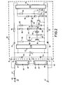
- reference numerals 1 and 2 denote input terminals which are intended to be connected to a supply voltage of approximately 118 volts, 60 Hz.
- the terminals 1 and 2 are interconnected by means of a series arrangement of a capacitor 3, a coil 4, and a low-pressure mercury vapour discharge tube 5 of approximately 36 Watts.
- Tube 5 has two preheatable electrodes 6 and 7.
- the sides of the electrodes 6 and 7 which face away from the terminals 1 and 2 are interconnected by a starter 8.
- the starter 8 is, for example, of a relay type as described in Netherlands Patent Application 7,700,764 (PHN 8660) or of a type described with reference to Fig. 2.
- a current first flows through the circuit 1, 3, 4, 6, 8, 7, 2. This causes the electrodes 6 and 7 of the discharge tube 5 to be heated. After some time the starter 8 will be rendered non-conductive as a result of which, by means of a voltage peak generated therefor in the coil 4, a high voltage will be produced between the electrodes 6 and 7 as a result of which the tube 5 ignites. The starter 8 then remains inoperative. Then only the circuit 1, 3, 4, 6, 7, 2 is in operation. Each time after the current has passed through zero the discharge tube 5 reignites on the combination of the residual voltage at the capacitor 3 and the instantaneous value of the input voltage between the terminals 1 ahd 2.
- the capacitor has a value of approximately 5.8 / u Farad, and the coil 4 has a value of approximately 0.47 Henry.
- the circular-cylindrical low-pressure mercury vapour discharge tube 5 has: an electrode spacing of approximately 112 cm, an inside diameter of approximately 2.4 cm, mercury in the discharge tube approximately 15 mgram, and the rare gas in the discharge tube comprises krypton 75 at.% and argon 25 at.%.
- the filling pressure (at 300 Kelvin) is approximately 200 Pascal and the arc voltage is approximately 103 volts.
- the lamp a of the discharge tube 5 When operated from a reference ballast in accordance with the IEC publication No. 82 the lamp a of the discharge tube 5 is approximately 0.8, i.e.located between 0.5 and 0.85.
- the system efficiency of this electric device is approximately 84 lumen/Watt.
- reference numerals 40 and 41 denote input terminals of a second electric device in accordance with the invention.
- the terminals 40 and 41 are intended to be connected to a supply voltage of nominal 220 Volts, 50 Hz.
- the terminals 40 and 41 are interconnected by a series arrangement of a capacitor 43, a coil 44, and two low-pressure mercury vapour discharge tubes 45 and 46 which are arranged in series with each other.
- the tubes 4 5 and 46 each comprise two preheatable electrodes 47, 48 and 49, 50, respectively.
- the electrodes 47 and 50 are interconnected via a lamp starter 60. There now follows a description of the lamp starter 60.
- the starter 60 has six input terminals: A, B, C, D, E, F.
- the terminal A is connected to a junction of the coil 44 and the electrode 47.
- the terminal B is connected to that side of electrode 47 whichfaces away from the terminal 40.
- the terminal C is connected to the electrode 48, and the terminal D to the electrode 49.
- the terminal E is connected to that side of electrode 50 which faces away from the terminal 41.
- the terminal F is connected to the input terminal 41.
- the terminal A is connected to the terminal C via a capacitor 70.
- the terminal D is connected to the terminal F via a capacitor 71.
- a spike suppressor 72 and a first diode bridge 73 are connected between the terminals B and E.
- Terminal B is also connected to terminal E by a series arrangement of a capacitor 74, a resistor 75, a second diode bridge 76, a resistor 77 and a capacitor 78.
- the output terminals of the first diode bridge 73 are interconnected by means of a series arrangement of a resistor 79, a winding 80 of a transformer, and a transistor 81.
- a further winding 82 of said transformer connects the base to the emitter of the transistor 81.
- Said base and emitter are also interconnected by a resistor 83.
- a bidirectional threshold element silicon bilateral switch (SBS) 84 the base of the transistor 81 is connected to the eollector of an auxiliary transistor 85.
- the emitter of this auxiliary transistor 85 is connected to the emitter of the transistor 81.
- a second series arrangement of a resistor 86, a zener diode 87 and a capacitor 88, and also a third series arrangement of two resistors 89 and 90, respectively are arranged in parallel with the series arrangement 79, 80, 81.
- a tapping point between the Zener diode 87 and the capacitor 88 is connected to a junction of the threshold element 84 and the collector of the auxiliary transistor 85.
- a tapping point between the resistor 89 and 90 is connected to a diode 92.
- Two output terminals of the second diode bridge are interconnected by means of a series arrangement of two resistors 93 and 94. Resistor 94 is by-passed by a capacitor 95.
- the said two output terminals of the second diode bridge 76 are interconnected by means of a series arrangement of a diode 96, a zener diode 97 and a resistor 98.
- the resistor 98 connects the base to the emitter of the auxiliary transistor 85.
- the cathode of the diode 92 is connected to a junction of the diode 96 and the zener diode 97.
- the starter 60 described in the foregoing has some resemblance to the starter of Netherlands Patent Application 7.502,053 (PHN 7892).
- the starter 60 With the starter 60 a number of reignition pulses having a low peak value are first generated and thereafter a number/of starting pulses having a high peak value.
- the starter 60 is made inoperative after some time as a result of the fact that the auxiliary transistor 85 has become conductive.
- the capacitor 43 has a value of approximately 3.7 / u Farad, and the coil 44 has a value approximately 1.3 Henry.
- the lamps 45 and 46 are of a similar type as the tube 5 of the device shown in Fig. 1. This means inter alia that the lamp ⁇ operated from the reference ballast mentioned in the foregoing amounts to 0.8.
- the capacitor 70 has a value of approximately 68 nF.
- the capacitor 71 has a value of approximately 22 nF.
- the capacitor 74 has a value of approximately 100 nF.
- the capacitor 78 has a value of approximately 100 nF.
- the capacitor 95 has a value of approximately 15 / uF.
- the transformation ratio of the transformer 82-80 is approximately 1:1.
- the resistor 75 has a value of approximately 270 k ⁇ .
- the resistor 77 has a value of approximately 270 k ⁇
- the resistor 86 has a value of approximately 20 k ⁇
- the resistor 89 has a value of approximately 36 0 k ⁇ .
- the resistor 90 has a value of approximately 10 k ⁇
- the resistor 91 has a value of approximately 22 k ⁇
- the resistor 93 has a value of approximately 1.5 k ⁇
- the resistor 94 has a value of approximately 120 k ⁇ .
- the resistor 98 has a value of approximately 22 k ⁇ .
- the zener voltage of the zener diode 87 is approximately 180 Volts.
- the zener voltage of the zener diode 97 is approximately 15 Volts.
- the lamp current is approximately 475 mA.
- the system efficiency is approximately 90 lumen/ Watt.
- Fig. 3 - by means of curve 80 - there is plotted the overall arc voltage B in Volts of the discharge tubes 45 and 46 of the example of Fig. 2, versus the mercury vapour pressure P (in Pascal). Also the temperature T in C of the coldest spot of the discharge tube wall is plotted in Fig. 3. The limits of 0.4 and 2 Pascal are shown in Fig. 3 by means of two broken lines. From this Figure it appears that the arc voltage has a maximum in said mercury vapour pressure interval.
- the cross on the curve 80 shows the operating point for the event that the nominal voltage of 200 Volts, 50 Hz is present between the input terminals 40 and 41 of the electric device shown in Fig. 2.
- the two electric devices described have only a small ballast and starter and reignite reliably in the voltage interval of plus or minus 10% of the nominal mains voltage.
- an electric device in accordance with the invention is arranged in the form of a lamp unit as, for example, described in Netherlands Patent Application 7,906,203 (PHN 9551).
Abstract
Description
- The invention relates to an electric device comprising at least one low-pressure mercury vapour discharge tube and having two input terminals, said input terminals being intended for connection to an a.c. voltage source the frequency of which is 50 to 60 Hz, and said input terminals being interconnected by means of a series arrangement of at least the low-pressure mercury vapour discharge tube, a capacitor and a coil, the capacitor impedance exceeding the coil impedance at the above-mentioned frequency, and in the operating condition the (overall) arc voltage of the low-pressure mercury vapour discharge tube (tubes), which form part of the series arrangement, being between 80% and 110% of the nominal voltage between the input terminals.
- A known electric device of the said type is, for example, described in Netherlands Patent Application 7,415,839 (PHN 7800). A disadvantage of that known device is that a second coil is present. That second coil is arranged in parallel with the discharge tube (discharge tubes). In the operating condition of the discharge tube (tubes) said second coil results in additional electric losses of that electric device.
- The invention has for its object to provide an electric device of the type defined in the preamble, wherein, in the operating condition, no parallel coil is required and the electric losses are small.
- According to the invention, an electric device comprising at least one low-pressure mercury vapour discharge tube and having two input terminals, said input terminals being intended for connection to an a.c. voltage source the frequency of which is 50 to 60 Hz, and said input terminals being interconnected by means of a series arrangement of at least the low-pressure mercury vapour discharge tube, a capacitor and a coil, the capacitor impedance exceeding the coil impedance at the above-mentioned frequency, and in the operating condition the (overall) arc voltage of the low-pressure mercury vapour discharge tube (tubes), which form part of the series arrangement, is between 80% and 110% of the nominal voltage between the input terminals, is characterized in that each low-pressure mercury vapour discharge tube which is part of the series arrangement is of a type which:
- a) if operated by means of a reference ballast in accordance with IEC publication No. 82 has a lamp value located between 0.5 and 0.85 if the rms voltage between two ends of a series arrangement formed by the reference ballast and the low-pressure mercury vapour discharge tube is approximately twice the arc-voltage of the discharge tube; and also
- b) in the presence of the nominal voltage between the input terminals of the electric device has a required reignition voltage which is less than

- An advantage of this electric device is that in the operating condition of the discharge tube (tubes) no parallel coil is required and that the electric losses are small. A further advantage is that - in spite of.the absence of the parallel coil - the discharge tube (tubes) still remains (remain) operative, even at small deviations of the nominal voltage, between the input terminals of the electric device. This will be explained in greater detail hereinafter. First the IEC publication and also the lamp α will be described.
- The above-mentioned publication No. 82 of the IEC (International Electrotechnical Commission) is entitled "Ballasts for tubular fluorescent lamps" ("Ballasts pour lampes tubulaires a fluorescence) 4th edition, 1980. In brief, a reference ballast is an inductive ballast having a substantially constant ratio between the voltage across that ballast-and the current through that ballast.
- is understood to mean: the quotient

- i is the instantaneous value of the current, in amperes, through the discharge tube;
- v is the instantaneous value of the voltage, in volts, across the discharge tube;
- w=2 π f, wherein f represents the frequency in Hz, t is the time in seconds;
- I is the effective current, in amperes, through the discharge tube: and
- V is the rms voltage, in volts, across the discharge tube.
- α is a distortion factor of the electric current,
- A smaller lamp α, when operated from a reference ballast, may, for example, be obtained by opting for a small cross-section of the discharge tube. The discharge tube may alternatively be filled with, for example, glass wool. See, for example, Netherlands Patent Specification 163,669 (PHN 7635).
- The "required reignition voltage" is understood to mean the instantaneous voltage, across the discharge tube, which must at least be present in each half cycle of the supply of that discharge tube in order to reignite said discharge tube. With an electric arrangement in accordance with the invention, the discharge tube reignites at a combination of the instantaneous mains voltage and a residual voltage on the ballast capacitor. The required reignition volt-age of a low-pressure mercury vapour discharge tube depends inter alia on the composition of the filler gas, which consists, for example, of a mixture of rare gases. Also the pressure of the filler gas influences the required reignition voltage.
- The following should be noted as regards the inventive idea. The second coil in an electric device described in the Netherlands Patent Application 7,415,839 (PHN 7800), mentioned in the foregoing, has for its object to make available in each half cycle of the supply a high voltage across the discharge tube to cause said discharge tube to reignite each time the current has passed through zero.
- It has surprisingly been found that in an electric device in accordance with the invention the discharge tube reignites readily, in spite of the absence of the second coil. It is conceivable that this is effected by a proportionally high residual voltage oil the capacitor, shortly after the current through the discharge tube has passed through zero. This may be caused by the effect that after said zero crossing the relevant discharge tube, having a low lamp α between 0,5 and 0,85, is highTohmic. This would namely block the discharge of the capacitor, causing the combination of the instantaneous mains voltage and the residual voltage on the capacitor to increase in a short period of time until the required reignition voltage of the discharge tube is reached. Said discharge tube reignites thereupon. If the lamp α exceeds 0.85, the lamp does not reignite, or at least less reliably. A lamp α of less than 0.5 has the disadvantage that the system efficiency of the device - for example exmpressed. in lumensper Watt - becomes comparatively low.
- The required reignition voltage of the discharge tube of an electric device in accordance with the invention must remain below a predetermined value in accordance with the condition b mentioned in the foregoing. Said required reignition voltage must namely be lower than the voltage which is available, for reigniting the discharge tube The available voltage depends inter alia on the number (n) of discharge tubes in the series circuit. This voltage is lower according as n is higher.
- It appears that also at a voltage between the input terminals of an electric device according to the invention which deviates to a small extent from the nominal voltage between the terminals the discharge tube (tubes) remain operative.
- The invention is based on the notion to realise a simple operating circuit by choosing a low-pressure mercury vapour discharge tube having a comparatively low lamp C( and a proportionally low required reignition voltage. It has been found that then small deviations from the nominal input voltage do not extinguish the discharge tube.
- It should be noted that an electric device comprising a high-pressure mercury vapour discharge tube and having two input terminals, said input terminals being intended for connection to an a.c. voltage source the frequency of which is 50 to 60 Hz, and said input terminals being interconnected by means of a series arrangement of at least the high-pressure mercury vapour discharge tube, a capacitor and a coil, the capacitor impedance exceeding at the above-mentioned frequency the coil impedance, and in the operating condition the arc voltage of the high-pressure mercury vapour discharge tube being substantially equal to the voltage between the input terminals, and the high-pressure mercury vapour discharge tube being of a type whose required reignition voltage is below a predetermined value, is known per se from United Kingdom Patent Specification 487,469 (PHZ 4945). However, said Patent Application does not relate to a low-pressure mercury vapour discharge tube but to a high-pressure mercury vapour discharge tube. In addition, said British Patent Specification does not furnish any information on the influence of mains voltage variations on the continued functioning of the discharge tube.
- In a preferred embodiment of an electric device in accordance with the invention the impedance of the coil at the specified frequency has been given such a low value - and consequently the current intensity in each individual low-pressure mercury vapour discharge tube which form part of the series arrangement is of such a high value - that in the operating condition with a nominal voltage between the input terminals the mercury vapour pressure in the discharge tube is between 0.4 and 2 Pascal, and the discharge tube is of a type the arc voltage - mercury vapour pressure characteristic of which has a maximum in the pressure range from 0.4 to 2 Pascal.
- An advantage of this preferred embodiment is that at the customary mains voltage variations (in thee range between 90% and 110% of the nominal mains voltage) a very reliable reignition of said discharge tube (tubes) can be obtained. An additional advantage is that the luminous efficacy (for example expressed in lumens/Watt) is comparatively large.
- It should be noted that it is known that in a low-pressure mercury vapour discharge tube an optimum conversion of electrical energy into radiation is accomplished at a mercury vapour pressure of approximately 0.75 Pascal.
- It is conceivable that the low-pressure mercury vapour discharge tube of an electric device in accordance with the invention is provided with an amalgam.
- In a next preferred embodiment of an electric device in accordance with the/invention each individual low-pressure mercury vapour discharge tube which forms part of the series arrangement is circular cylindrical and has an inside diameter of approximately 24 mm, and that discharge tube contains a rare gas containing at least 50 at.% krypton the filling pressure of which amounts from 100 to 300 Pascal. An advantage of this preferred embodiment is that the system efficiency of the electric device is comparatively high.
- In a further preferred embodiment of an electric device in accordance with the invention which is intended to be connected to an a.c. voltage source of a nominal voltage of 220 volts and 50 Hz the series arrangement of the electric device is provided with two-substantially identical -low-pressure mercury vapour discharge tubes, and the arc voltage of each of those discharge tubes is 100 to 110 volts. An advantage of this preferred embodiment is that the. electric device may be provided with low-pressure mercury vapour discharge tubes of a standard type.
- The invention will now be further described by way of example with reference to a drawing in which:
- Fig. 1 shows an electric device in accordance with the invention provided with a low-pressure mercury vapour discharge tube;
- Fig. 2 shows a second electric device in accordance with the invention comprising two series-arranged, low-pressure mercury vapour discharge tubes;
- Fig. 3 is the arc voltage-mercury vapour pressure characteristic of the assembly of discharge tubes shown in Fig. 2.
- In Fig. 1,
reference numerals 1 and 2 denote input terminals which are intended to be connected to a supply voltage of approximately 118 volts, 60 Hz. Theterminals 1 and 2 are interconnected by means of a series arrangement of acapacitor 3, acoil 4, and a low-pressure mercuryvapour discharge tube 5 of approximately 36 Watts.Tube 5 has twopreheatable electrodes electrodes terminals 1 and 2 are interconnected by a starter 8. The starter 8 is, for example, of a relay type as described in Netherlands Patent Application 7,700,764 (PHN 8660) or of a type described with reference to Fig. 2. - If the
terminals 1 and 2 are connected to the relevant supply source, a current first flows through thecircuit electrodes discharge tube 5 to be heated. After some time the starter 8 will be rendered non-conductive as a result of which, by means of a voltage peak generated therefor in thecoil 4, a high voltage will be produced between theelectrodes tube 5 ignites. The starter 8 then remains inoperative. Then only thecircuit discharge tube 5 reignites on the combination of the residual voltage at thecapacitor 3 and the instantaneous value of the input voltage between the terminals 1ahd 2. In a practical embodiment the capacitor has a value of approximately 5.8 /u Farad, and thecoil 4 has a value of approximately 0.47 Henry. The circular-cylindrical low-pressure mercuryvapour discharge tube 5 has: an electrode spacing of approximately 112 cm, an inside diameter of approximately 2.4 cm, mercury in the discharge tube approximately 15 mgram, and the rare gas in the discharge tube compriseskrypton 75 at.% and argon 25 at.%. - The filling pressure (at 300 Kelvin) is approximately 200 Pascal and the arc voltage is approximately 103 volts.
- When operated from a reference ballast in accordance with the IEC publication No. 82 the lamp a of the
discharge tube 5 is approximately 0.8, i.e.located between 0.5 and 0.85. - The nominal voltage of 118 volts, 60 Hz, being available between the
input terminals 1 and 2, the required reignition voltage of thedischarge tube 5 is approximately 180 volts, i.e. less than 170 % of 118 Volts = 200 Volts, where n = 1 for the case of Fig. 1. - The system efficiency of this electric device is approximately 84 lumen/Watt.
- In Fig. 2
reference numerals terminals terminals capacitor 43, acoil 44, and two low-pressure mercuryvapour discharge tubes tubes preheatable electrodes electrodes lamp starter 60. There now follows a description of thelamp starter 60. - The
starter 60 has six input terminals: A, B, C, D, E, F. The terminal A is connected to a junction of thecoil 44 and theelectrode 47. The terminal B is connected to that side ofelectrode 47 whichfaces away from the terminal 40. The terminal C is connected to theelectrode 48, and the terminal D to theelectrode 49. The terminal E is connected to that side ofelectrode 50 which faces away from the terminal 41. The terminal F is connected to theinput terminal 41. - The terminal A is connected to the terminal C via a
capacitor 70. The terminal D is connected to the terminal F via a capacitor 71. - A
spike suppressor 72 and afirst diode bridge 73 are connected between the terminals B and E. Terminal B is also connected to terminal E by a series arrangement of acapacitor 74, aresistor 75, a second diode bridge 76, aresistor 77 and acapacitor 78. - The output terminals of the
first diode bridge 73 are interconnected by means of a series arrangement of aresistor 79, a winding 80 of a transformer, and atransistor 81. A further winding 82 of said transformer connects the base to the emitter of thetransistor 81. Said base and emitter are also interconnected by aresistor 83. - Via a bidirectional threshold element (silicon bilateral switch) (SBS) 84 the base of the
transistor 81 is connected to the eollector of anauxiliary transistor 85. The emitter of thisauxiliary transistor 85 is connected to the emitter of thetransistor 81. - A second series arrangement of a
resistor 86, azener diode 87 and acapacitor 88, and also a third series arrangement of tworesistors series arrangement - Via a resistor 91 a tapping point between the
Zener diode 87 and thecapacitor 88 is connected to a junction of thethreshold element 84 and the collector of theauxiliary transistor 85. A tapping point between theresistor diode 92. - Two output terminals of the second diode bridge are interconnected by means of a series arrangement of two
resistors Resistor 94 is by-passed by acapacitor 95. The said two output terminals of the second diode bridge 76 are interconnected by means of a series arrangement of adiode 96, azener diode 97 and aresistor 98. Theresistor 98 connects the base to the emitter of theauxiliary transistor 85. The cathode of thediode 92 is connected to a junction of thediode 96 and thezener diode 97. - The
starter 60 described in the foregoing has some resemblance to the starter of Netherlands Patent Application 7.502,053 (PHN 7892). - With the starter 60 a number of reignition pulses having a low peak value are first generated and thereafter a number/of starting pulses having a high peak value. The
starter 60 is made inoperative after some time as a result of the fact that theauxiliary transistor 85 has become conductive. - In a practical embodiment the
capacitor 43 has a value of approximately 3.7/u Farad, and thecoil 44 has a value approximately 1.3 Henry. - The
lamps tube 5 of the device shown in Fig. 1. This means inter alia that the lamp α operated from the reference ballast mentioned in the foregoing amounts to 0.8. - The
capacitor 70 has a value of approximately 68 nF. - The capacitor 71 has a value of approximately 22 nF.
- The
capacitor 74 has a value of approximately 100 nF. - The
capacitor 78 has a value of approximately 100 nF. - The
capacitor 95 has a value of approximately 15 /uF. - The transformation ratio of the transformer 82-80 is approximately 1:1.
- The
resistor 75 has a value of approximately 270 kΩ. - The resistor 77has a value of approximately 270 k Ω
- The
resistor 86 has a value of approximately 20 kΩ - The
resistor 89 has a value of approximately 360 k Ω . - The
resistor 90 has a value of approximately 10 k Ω - The
resistor 91 has a value of approximately 22 k Ω - The
resistor 93 has a value of approximately 1.5 k Ω - The
resistor 94 has a value of approximately 120 kΩ. - The
resistor 98 has a value of approximately 22 k Ω. - The zener voltage of the
zener diode 87 is approximately 180 Volts. - The zener voltage of the
zener diode 97 is approximately 15 Volts. - In this embodiment the lamp current is approximately 475 mA. The required reignition voltage for each of the two discharge tubes is less than

- The system efficiency is approximately 90 lumen/ Watt.
- In Fig. 3 - by means of curve 80 - there is plotted the overall arc voltage B in Volts of the
discharge tubes - The cross on the
curve 80 shows the operating point for the event that the nominal voltage of 200 Volts, 50 Hz is present between theinput terminals - The two electric devices described have only a small ballast and starter and reignite reliably in the voltage interval of plus or minus 10% of the nominal mains voltage.
- It is conceivable that an electric device in accordance with the invention is arranged in the form of a lamp unit as, for example, described in Netherlands Patent Application 7,906,203 (PHN 9551).
Claims (4)
Applications Claiming Priority (2)
| Application Number | Priority Date | Filing Date | Title |
|---|---|---|---|
| NL8101408A NL8101408A (en) | 1981-03-23 | 1981-03-23 | ELECTRICAL DEVICE WITH AT LEAST A LOW-PRESSURE MERCURY VAPOR DISCHARGE TUBE. |
| NL8101408 | 1981-03-23 |
Publications (2)
| Publication Number | Publication Date |
|---|---|
| EP0061796A1 true EP0061796A1 (en) | 1982-10-06 |
| EP0061796B1 EP0061796B1 (en) | 1985-06-05 |
Family
ID=19837207
Family Applications (1)
| Application Number | Title | Priority Date | Filing Date |
|---|---|---|---|
| EP82200297A Expired EP0061796B1 (en) | 1981-03-23 | 1982-03-08 | Electric device comprising at least one low-pressure mercury vapour discharge tube |
Country Status (8)
| Country | Link |
|---|---|
| US (1) | US4443739A (en) |
| EP (1) | EP0061796B1 (en) |
| JP (1) | JPS57170498A (en) |
| BR (1) | BR8201576A (en) |
| CA (1) | CA1178651A (en) |
| DE (1) | DE3263991D1 (en) |
| HU (1) | HU183859B (en) |
| NL (1) | NL8101408A (en) |
Cited By (2)
| Publication number | Priority date | Publication date | Assignee | Title |
|---|---|---|---|---|
| EP1051060A1 (en) * | 1999-05-07 | 2000-11-08 | Yousef Husni Barikhan | Electronic starting device for fluorescent discharge lamps and the like,having improved characteristics |
| US6528144B2 (en) | 1997-09-23 | 2003-03-04 | Hoechst Diafoil Gmbh | Biaxially oriented polyester film, the use thereof, and process for the production thereof |
Families Citing this family (4)
| Publication number | Priority date | Publication date | Assignee | Title |
|---|---|---|---|---|
| US5049789A (en) * | 1990-01-12 | 1991-09-17 | Council Of Scientific & Industrial Research | Electronic capacitive ballast for fluorescent and other discharge lamps |
| US5449989A (en) * | 1992-07-31 | 1995-09-12 | Correa; Paulo N. | Energy conversion system |
| US5825139A (en) * | 1995-11-02 | 1998-10-20 | Hubbell Incorporated | Lamp driven voltage transformation and ballasting system |
| HUP1000054A3 (en) * | 2010-01-26 | 2012-08-28 | Gradix Holdings Ltd | Ac voltage converter and switching equipment |
Citations (3)
| Publication number | Priority date | Publication date | Assignee | Title |
|---|---|---|---|---|
| DE2453253A1 (en) * | 1974-10-23 | 1976-04-29 | Bbc Brown Boveri & Cie | Ballast unit for ignition of fluorescent lamps - cathodes heated before ignition while ignition is by circuit interruption |
| NL7415839A (en) * | 1974-12-05 | 1976-06-09 | Philips Nv | ELECTRICAL DEVICE FOR IGNITION AND FEEDING A GAS AND / OR VAPOR DISCHARGE LAMP. |
| NL7806889A (en) * | 1978-06-27 | 1980-01-02 | Philips Nv | ELECTRICAL APPARATUS WITH AT LEAST A GAS AND / OR VAPOR DISCHARGE TUBE. |
Family Cites Families (7)
| Publication number | Priority date | Publication date | Assignee | Title |
|---|---|---|---|---|
| US2465031A (en) * | 1946-08-08 | 1949-03-22 | Nathanson Max | Fluorescent tube lighting system |
| US2853653A (en) * | 1953-04-16 | 1958-09-23 | Gen Electric | Sequence boost circuit for discharge lamps |
| US3324349A (en) * | 1963-04-16 | 1967-06-06 | Philips Corp | Device employing two gas- and/or vapour-discharge tubes |
| NL7402779A (en) * | 1974-03-01 | 1975-09-03 | Philips Nv | DEVICE EQUIPPED WITH A GAS AND / OR VAPOR DISCHARGE LAMP. |
| US4039895A (en) * | 1975-02-20 | 1977-08-02 | U.S. Philips Corporation | Device for starting and feeding a discharge lamp |
| NL179779C (en) * | 1977-01-26 | 1986-11-03 | Philips Nv | DEVICE FOR IGNITION AND POWERING A GAS AND / OR VAPOR DISCHARGE LAMP. |
| NL7909128A (en) * | 1979-12-19 | 1981-07-16 | Philips Nv | ELECTRONIC AUXILIARY DEVICE FOR STARTING AND ACCOUNTING OPERATIONS OF A GAS AND / OR VAPOR DISCHARGE LAMP. |
-
1981
- 1981-03-23 NL NL8101408A patent/NL8101408A/en not_active Application Discontinuation
-
1982
- 1982-02-25 US US06/352,505 patent/US4443739A/en not_active Expired - Lifetime
- 1982-03-08 DE DE8282200297T patent/DE3263991D1/en not_active Expired
- 1982-03-08 EP EP82200297A patent/EP0061796B1/en not_active Expired
- 1982-03-18 CA CA000398700A patent/CA1178651A/en not_active Expired
- 1982-03-19 HU HU82845A patent/HU183859B/en unknown
- 1982-03-19 JP JP57043015A patent/JPS57170498A/en active Pending
- 1982-03-22 BR BR8201576A patent/BR8201576A/en unknown
Patent Citations (3)
| Publication number | Priority date | Publication date | Assignee | Title |
|---|---|---|---|---|
| DE2453253A1 (en) * | 1974-10-23 | 1976-04-29 | Bbc Brown Boveri & Cie | Ballast unit for ignition of fluorescent lamps - cathodes heated before ignition while ignition is by circuit interruption |
| NL7415839A (en) * | 1974-12-05 | 1976-06-09 | Philips Nv | ELECTRICAL DEVICE FOR IGNITION AND FEEDING A GAS AND / OR VAPOR DISCHARGE LAMP. |
| NL7806889A (en) * | 1978-06-27 | 1980-01-02 | Philips Nv | ELECTRICAL APPARATUS WITH AT LEAST A GAS AND / OR VAPOR DISCHARGE TUBE. |
Cited By (2)
| Publication number | Priority date | Publication date | Assignee | Title |
|---|---|---|---|---|
| US6528144B2 (en) | 1997-09-23 | 2003-03-04 | Hoechst Diafoil Gmbh | Biaxially oriented polyester film, the use thereof, and process for the production thereof |
| EP1051060A1 (en) * | 1999-05-07 | 2000-11-08 | Yousef Husni Barikhan | Electronic starting device for fluorescent discharge lamps and the like,having improved characteristics |
Also Published As
| Publication number | Publication date |
|---|---|
| DE3263991D1 (en) | 1985-07-11 |
| EP0061796B1 (en) | 1985-06-05 |
| US4443739A (en) | 1984-04-17 |
| HU183859B (en) | 1984-06-28 |
| JPS57170498A (en) | 1982-10-20 |
| BR8201576A (en) | 1983-02-08 |
| CA1178651A (en) | 1984-11-27 |
| NL8101408A (en) | 1982-10-18 |
Similar Documents
| Publication | Publication Date | Title |
|---|---|---|
| US4447759A (en) | Starter for igniting an electric discharge tube | |
| US6091208A (en) | Lamp ignitor for starting conventional hid lamps and for starting and restarting hid lamps with hot restrike capability | |
| EP0150536B1 (en) | Ballast adaptor for improving operation of fluorescent lamps | |
| JPS587230B2 (en) | metal vapor discharge lamp | |
| US4185233A (en) | High efficiency ballast system for gaseous discharge lamps | |
| US4339695A (en) | High pressure sodium lamp ballast circuit | |
| EP0061796B1 (en) | Electric device comprising at least one low-pressure mercury vapour discharge tube | |
| CA2037667C (en) | Ignitor for high pressure arc discharge lamps | |
| US4103209A (en) | Add-on instant restrike device for an hid lamp | |
| US4134043A (en) | Lighting circuits | |
| EP0181666B1 (en) | High-pressure discharge lamp | |
| US5606222A (en) | Lighting system with a device for reducing system wattage | |
| US4769578A (en) | High-pressure sodium discharge lamp | |
| US4236100A (en) | Lighting circuits | |
| US2682014A (en) | Apparatus for starting and operating gaseous discharge devices | |
| US4808888A (en) | Starting circuit for gaseous discharge lamps | |
| WO1995028068A1 (en) | Circuit arrangement | |
| EP0054271B1 (en) | Discharge lamp starting and operating circuit | |
| CA1060536A (en) | Starting and operating circuit for gaseous discharge lamps | |
| US4185231A (en) | High efficiency ballast system for gaseous discharge lamps | |
| US3745409A (en) | Combination of a low-pressure mercury vapour discharge lamp and a glow discharge starter | |
| EP0181667B1 (en) | Circuit arrangement for operating a high-pressure discharge lamp | |
| US4513225A (en) | Fluorescent lamp series system | |
| EP0198536A1 (en) | Adaption circuit for operating a high-pressure discharge lamp | |
| EP0189122B1 (en) | Metal vapor lamp starting and operating apparatus |
Legal Events
| Date | Code | Title | Description |
|---|---|---|---|
| PUAI | Public reference made under article 153(3) epc to a published international application that has entered the european phase |
Free format text: ORIGINAL CODE: 0009012 |
|
| 17P | Request for examination filed |
Effective date: 19820308 |
|
| AK | Designated contracting states |
Designated state(s): BE CH DE FR GB NL |
|
| GRAA | (expected) grant |
Free format text: ORIGINAL CODE: 0009210 |
|
| AK | Designated contracting states |
Designated state(s): BE CH DE FR GB LI NL |
|
| REF | Corresponds to: |
Ref document number: 3263991 Country of ref document: DE Date of ref document: 19850711 |
|
| ET | Fr: translation filed | ||
| PLBE | No opposition filed within time limit |
Free format text: ORIGINAL CODE: 0009261 |
|
| STAA | Information on the status of an ep patent application or granted ep patent |
Free format text: STATUS: NO OPPOSITION FILED WITHIN TIME LIMIT |
|
| 26N | No opposition filed | ||
| PGFP | Annual fee paid to national office [announced via postgrant information from national office to epo] |
Ref country code: GB Payment date: 19900228 Year of fee payment: 9 |
|
| PGFP | Annual fee paid to national office [announced via postgrant information from national office to epo] |
Ref country code: BE Payment date: 19900312 Year of fee payment: 9 |
|
| PGFP | Annual fee paid to national office [announced via postgrant information from national office to epo] |
Ref country code: FR Payment date: 19900320 Year of fee payment: 9 |
|
| PGFP | Annual fee paid to national office [announced via postgrant information from national office to epo] |
Ref country code: NL Payment date: 19900331 Year of fee payment: 9 |
|
| PGFP | Annual fee paid to national office [announced via postgrant information from national office to epo] |
Ref country code: DE Payment date: 19900523 Year of fee payment: 9 |
|
| PGFP | Annual fee paid to national office [announced via postgrant information from national office to epo] |
Ref country code: CH Payment date: 19900627 Year of fee payment: 9 |
|
| PG25 | Lapsed in a contracting state [announced via postgrant information from national office to epo] |
Ref country code: GB Effective date: 19910308 |
|
| PG25 | Lapsed in a contracting state [announced via postgrant information from national office to epo] |
Ref country code: LI Effective date: 19910331 Ref country code: CH Effective date: 19910331 Ref country code: BE Effective date: 19910331 |
|
| BERE | Be: lapsed |
Owner name: N.V. PHILIPS' GLOEILAMPENFABRIKEN Effective date: 19910331 |
|
| PG25 | Lapsed in a contracting state [announced via postgrant information from national office to epo] |
Ref country code: NL Effective date: 19911001 |
|
| GBPC | Gb: european patent ceased through non-payment of renewal fee | ||
| NLV4 | Nl: lapsed or anulled due to non-payment of the annual fee | ||
| PG25 | Lapsed in a contracting state [announced via postgrant information from national office to epo] |
Ref country code: FR Effective date: 19911129 |
|
| REG | Reference to a national code |
Ref country code: CH Ref legal event code: PL |
|
| PG25 | Lapsed in a contracting state [announced via postgrant information from national office to epo] |
Ref country code: DE Effective date: 19920101 |
|
| REG | Reference to a national code |
Ref country code: FR Ref legal event code: ST |