EP0061584A1 - Pregrooved optical-disk - Google Patents
Pregrooved optical-disk Download PDFInfo
- Publication number
- EP0061584A1 EP0061584A1 EP82101402A EP82101402A EP0061584A1 EP 0061584 A1 EP0061584 A1 EP 0061584A1 EP 82101402 A EP82101402 A EP 82101402A EP 82101402 A EP82101402 A EP 82101402A EP 0061584 A1 EP0061584 A1 EP 0061584A1
- Authority
- EP
- European Patent Office
- Prior art keywords
- layer
- disk
- optical
- tracking
- refractive index
- Prior art date
- Legal status (The legal status is an assumption and is not a legal conclusion. Google has not performed a legal analysis and makes no representation as to the accuracy of the status listed.)
- Granted
Links
Images

Classifications
-
- G—PHYSICS
- G11—INFORMATION STORAGE
- G11B—INFORMATION STORAGE BASED ON RELATIVE MOVEMENT BETWEEN RECORD CARRIER AND TRANSDUCER
- G11B7/00—Recording or reproducing by optical means, e.g. recording using a thermal beam of optical radiation by modifying optical properties or the physical structure, reproducing using an optical beam at lower power by sensing optical properties; Record carriers therefor
- G11B7/24—Record carriers characterised by shape, structure or physical properties, or by the selection of the material
- G11B7/26—Apparatus or processes specially adapted for the manufacture of record carriers
-
- G—PHYSICS
- G11—INFORMATION STORAGE
- G11B—INFORMATION STORAGE BASED ON RELATIVE MOVEMENT BETWEEN RECORD CARRIER AND TRANSDUCER
- G11B7/00—Recording or reproducing by optical means, e.g. recording using a thermal beam of optical radiation by modifying optical properties or the physical structure, reproducing using an optical beam at lower power by sensing optical properties; Record carriers therefor
- G11B7/24—Record carriers characterised by shape, structure or physical properties, or by the selection of the material
- G11B7/241—Record carriers characterised by shape, structure or physical properties, or by the selection of the material characterised by the selection of the material
- G11B7/252—Record carriers characterised by shape, structure or physical properties, or by the selection of the material characterised by the selection of the material of layers other than recording layers
- G11B7/257—Record carriers characterised by shape, structure or physical properties, or by the selection of the material characterised by the selection of the material of layers other than recording layers of layers having properties involved in recording or reproduction, e.g. optical interference layers or sensitising layers or dielectric layers, which are protecting the recording layers
- G11B7/2572—Record carriers characterised by shape, structure or physical properties, or by the selection of the material characterised by the selection of the material of layers other than recording layers of layers having properties involved in recording or reproduction, e.g. optical interference layers or sensitising layers or dielectric layers, which are protecting the recording layers consisting essentially of organic materials
- G11B7/2575—Record carriers characterised by shape, structure or physical properties, or by the selection of the material characterised by the selection of the material of layers other than recording layers of layers having properties involved in recording or reproduction, e.g. optical interference layers or sensitising layers or dielectric layers, which are protecting the recording layers consisting essentially of organic materials resins
-
- G—PHYSICS
- G11—INFORMATION STORAGE
- G11B—INFORMATION STORAGE BASED ON RELATIVE MOVEMENT BETWEEN RECORD CARRIER AND TRANSDUCER
- G11B7/00—Recording or reproducing by optical means, e.g. recording using a thermal beam of optical radiation by modifying optical properties or the physical structure, reproducing using an optical beam at lower power by sensing optical properties; Record carriers therefor
- G11B7/24—Record carriers characterised by shape, structure or physical properties, or by the selection of the material
- G11B7/241—Record carriers characterised by shape, structure or physical properties, or by the selection of the material characterised by the selection of the material
- G11B7/242—Record carriers characterised by shape, structure or physical properties, or by the selection of the material characterised by the selection of the material of recording layers
- G11B7/243—Record carriers characterised by shape, structure or physical properties, or by the selection of the material characterised by the selection of the material of recording layers comprising inorganic materials only, e.g. ablative layers
- G11B2007/24302—Metals or metalloids
- G11B2007/24316—Metals or metalloids group 16 elements (i.e. chalcogenides, Se, Te)
-
- G—PHYSICS
- G11—INFORMATION STORAGE
- G11B—INFORMATION STORAGE BASED ON RELATIVE MOVEMENT BETWEEN RECORD CARRIER AND TRANSDUCER
- G11B7/00—Recording or reproducing by optical means, e.g. recording using a thermal beam of optical radiation by modifying optical properties or the physical structure, reproducing using an optical beam at lower power by sensing optical properties; Record carriers therefor
- G11B7/24—Record carriers characterised by shape, structure or physical properties, or by the selection of the material
- G11B7/241—Record carriers characterised by shape, structure or physical properties, or by the selection of the material characterised by the selection of the material
- G11B7/252—Record carriers characterised by shape, structure or physical properties, or by the selection of the material characterised by the selection of the material of layers other than recording layers
- G11B7/254—Record carriers characterised by shape, structure or physical properties, or by the selection of the material characterised by the selection of the material of layers other than recording layers of protective topcoat layers
- G11B2007/25408—Record carriers characterised by shape, structure or physical properties, or by the selection of the material characterised by the selection of the material of layers other than recording layers of protective topcoat layers consisting essentially of inorganic materials
- G11B2007/25417—Record carriers characterised by shape, structure or physical properties, or by the selection of the material characterised by the selection of the material of layers other than recording layers of protective topcoat layers consisting essentially of inorganic materials containing Group 14 elements (C, Si, Ge, Sn)
-
- G—PHYSICS
- G11—INFORMATION STORAGE
- G11B—INFORMATION STORAGE BASED ON RELATIVE MOVEMENT BETWEEN RECORD CARRIER AND TRANSDUCER
- G11B7/00—Recording or reproducing by optical means, e.g. recording using a thermal beam of optical radiation by modifying optical properties or the physical structure, reproducing using an optical beam at lower power by sensing optical properties; Record carriers therefor
- G11B7/24—Record carriers characterised by shape, structure or physical properties, or by the selection of the material
- G11B7/241—Record carriers characterised by shape, structure or physical properties, or by the selection of the material characterised by the selection of the material
- G11B7/252—Record carriers characterised by shape, structure or physical properties, or by the selection of the material characterised by the selection of the material of layers other than recording layers
- G11B7/253—Record carriers characterised by shape, structure or physical properties, or by the selection of the material characterised by the selection of the material of layers other than recording layers of substrates
- G11B7/2531—Record carriers characterised by shape, structure or physical properties, or by the selection of the material characterised by the selection of the material of layers other than recording layers of substrates comprising glass
-
- G—PHYSICS
- G11—INFORMATION STORAGE
- G11B—INFORMATION STORAGE BASED ON RELATIVE MOVEMENT BETWEEN RECORD CARRIER AND TRANSDUCER
- G11B7/00—Recording or reproducing by optical means, e.g. recording using a thermal beam of optical radiation by modifying optical properties or the physical structure, reproducing using an optical beam at lower power by sensing optical properties; Record carriers therefor
- G11B7/24—Record carriers characterised by shape, structure or physical properties, or by the selection of the material
- G11B7/241—Record carriers characterised by shape, structure or physical properties, or by the selection of the material characterised by the selection of the material
- G11B7/252—Record carriers characterised by shape, structure or physical properties, or by the selection of the material characterised by the selection of the material of layers other than recording layers
- G11B7/253—Record carriers characterised by shape, structure or physical properties, or by the selection of the material characterised by the selection of the material of layers other than recording layers of substrates
- G11B7/2533—Record carriers characterised by shape, structure or physical properties, or by the selection of the material characterised by the selection of the material of layers other than recording layers of substrates comprising resins
-
- G—PHYSICS
- G11—INFORMATION STORAGE
- G11B—INFORMATION STORAGE BASED ON RELATIVE MOVEMENT BETWEEN RECORD CARRIER AND TRANSDUCER
- G11B7/00—Recording or reproducing by optical means, e.g. recording using a thermal beam of optical radiation by modifying optical properties or the physical structure, reproducing using an optical beam at lower power by sensing optical properties; Record carriers therefor
- G11B7/24—Record carriers characterised by shape, structure or physical properties, or by the selection of the material
- G11B7/241—Record carriers characterised by shape, structure or physical properties, or by the selection of the material characterised by the selection of the material
- G11B7/252—Record carriers characterised by shape, structure or physical properties, or by the selection of the material characterised by the selection of the material of layers other than recording layers
- G11B7/254—Record carriers characterised by shape, structure or physical properties, or by the selection of the material characterised by the selection of the material of layers other than recording layers of protective topcoat layers
- G11B7/2542—Record carriers characterised by shape, structure or physical properties, or by the selection of the material characterised by the selection of the material of layers other than recording layers of protective topcoat layers consisting essentially of organic resins
Definitions
- the present invention relates to an optical type information recording medium and, more particularly, to an optical-disk for recording and/or reconstruction of information signals using an energy beam such as laser.
- optical-disks have been developed as one type of recording media which are capable of recording information at high density and big capacity.
- tracking grooves about 0.6 ⁇ m in width and 1.5 to 2 ⁇ m in pitch are formed in the optical-disk in advance, and a focused laser beam having a spot diameter of about 1 ⁇ m is radiated on the groove to record information signals.
- the tracking control is performed through detection of the changes in the levels of reflected light signals and transmitted light signals which correspond to the positional relationship between the tracking grooves and the beam spot of the laser beam on the optical disk.
- the recording/reconstruction apparatus includes a differentiator and a single axis position sensor which receives the light signals by dividing them into halves to generate first and second electric signals.
- the single axis position sensor When the center of the laser beam spot coincides with the center of the tracking groove, the single axis position sensor generates first and second electric signals which do not have any level difference.
- the single axis position sensor When the center of the beam spot deviates from the center of the tracking groove in the radial direction of the optical-disk, the single axis position sensor generates first and second electric signals which have a level difference which depends on the direction and magnitude of this deviation. By differentiating this level difference, the deviation (tracking error) may be detected. By correcting this tracking error, the laser beam spot is returned to central position and tracking control may be performed with high precision.
- the change in the intensity of the reflected light which corresponds to the presence or absence of a pit which is formed in the tracking groove of the optical-disk, is detected by an adding amplifier which adds the first and second electric signals which are generated by the single axis position sensor.
- the shape of the tracking groove formed in the optical-disk as described above is preferably such that the influence of the presence of the tracking groove on the addition result obtained from the single axis position sensor may be reduced to the minimum, and yet the percentage modulation of the differential output may be increased: which output corresponds to the deviation of the center of the laser beam spot from the center of the tracking groove, that is, the tracking error.
- Japanese Patent Disclosures (KOKAI) No. 55,448/80 and No. 55, 4 49/80 propose a V-shaped groove which has an inclination angle of about 80 to 85 degrees.
- IEEE SPECTRUM AUGUST, 1979, pp. 26 to 33 proposes a rectangular groove according to which the phase difference between the signals obtained in correspondence with the interior and exterior of the tracking groove equals ⁇ (m/8), where m is an odd integer and X is the wavelength of the laser beam used.
- a pregrooved optical-disk of the present invention has a first layer having a surface on which is formed a tracking groove, and a second layer which is formed on the surface of the first layer.
- the first layer is made of a transparent substance which has a refractive index n l whereas the second layer is made of another transparent substance which has a refractive index n 2 .
- a recording layer is formed on the substantially flat surface of the second layer. An energy beam such as laser is radiated on this recording layer through at least the first and second layers.
- the recording layer is made of a substance which is melted when the energy of the incident energy beam exceeds a predetermined energy level.
- Fig. 1 is a schematic sectional view of an optical-disk 10 along the radial direction thereof, which is an example of prior art optical type information recording media.
- a transparent substrate 11 In one surface of a transparent substrate 11 are formed recesses 12-1, 12-2 and so on which are continuous in a spiral shape and which have a rectangular section of about 0.6 ⁇ m width. These recesses, that is, tracking grooves 12, are formed by the known injection technique.
- a recording layer 14 of a predetermined 0 thickness, for example, 600 A, is deposited on the surface of the substrate 11 in which the tracking grooves 12 are formed.
- the recording layer 14 is made of tellurium or a compound thereof.
- the overall thickness of the optical-disk 10 of this configuration is set to be about 1.5 mm, for example, (substantially equal to the thickness of one substrate), and the diameter thereof is set to be 300 mm.
- Fig. 2 shows schematically the configuration of the main part of an information recording/reconstruction apparatus which includes the optical-disk 10 shown in Fig. 1.
- a laser beam 20 which is emitted from a laser beam source (not shown) and transmitted through a modulator (not shown) becomes-incident on a polarization beam splitter 24 through a lens 22.
- the laser beam components which have been transmitted through the polarization beam splitter 24 become incident on the optical-disk 10 from the side of the transparent substrate 11 through a lens 26, a quarter wave plate 28, a rotary mirror 30, and a condenser (objective lens) 32.
- the other beam components which emerge from the polarization beam splitter 24 are radiated on a single axis position sensor 34 which has two subdivided photosensors.
- Two output signals from the single axis position sensor 34 are supplied to an adding amplifier (adder) 36 as well as to a differentiator 38.
- the output terminal of the differentiator 38 is connected to the input terminal of a mirror driver 40 which drives the rotary mirror 30 in response to a tracking control signal 42 output from the differentiator 38.
- a pulse laser beam 44 (Fig. 1) which corresponds to the recording information according to the known Pulse Code Modulation technique and which is focused on a spot of a predetermined diameter, for example, 1 ⁇ m radiates the tracking groove 12-2 of the optical-disk 10. Then, that part of the recording layer 14 which corresponds to the tracking groove 12-2 melts by means of the energy in the pulse laser beam 44. In this manner, a recess or opening which is generally called a pit is formed, so that the information is recorded.
- a reconstruction laser beam which has an energy level lower than that of the pulse laser beam 44 is radiated on the optical-disk 10, in the same direction as the pulse laser beam 44 for recording, to optically read the pit, so that the recorded information may be reconstructed.
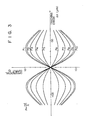
- Fig. 3 shows characteristic curves representing the correlation between the differential output generated from the differentiator 38 and the position of the spot of the laser beam incident on the optical-disk 10 in the information recording/reconstruction apparatus shown in Fig. 2.
- Fig. 3 along the abscissa is plotted the tracking error ⁇ x( ⁇ m) between the center of the spot of the laser beam which is incident of the optical-disk 10 and the center of the tracking groove, and along the ordinate is plotted the differential output I D which is output from the differentiator 38.
- n the refractive index of the transparent substrate 11
- d the depth in ⁇ m of the tracking groove 12
- ⁇ the wavelength in ⁇ m of the laser beam used.
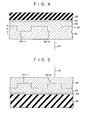
- Fig. 4 is a sectional view of an optical-disk 50 along the radial direction thereof according to an embodiment of the present invention.
- a transparent layer 56 is formed on the transparent substrate 52 by application of a known spinner or the like.
- a recording layer 58 and a protective layer 60 are formed on the transparent layer 56.
- the refractive index of the transparent substrate 52 is represented by n l
- the refractive index of the transparent layer 56 is represented by n 2 .
- the allowable error E r of the depth d of the tracking groove 54 is obtained as:
- the value of An must be made smaller in order to increase the allowable error E r of the depth d of the tracking groove 54 during manufacture of the optical-disk 50 shown in Fig. 4. Accordingly, the value of An is set to be within the range of 0.01 to 0.5, preferably within the range of 0.02 to 0.2.
- the value of ⁇ n is less than 0.01, it is difficult to manufacture the transparent substrate 52 which has guide grooves which, in turn, have a depth of 0.633/8 x 0.01 ⁇ 8 ⁇ m.
- the value of An is above 0.5, the advantageous effects of the present invention are hard to obtain.
- the transparent substrate 52 is made of a polymethyl methacrylate (PMMA) having a refractive index n 1 of about 1.49.
- the transparent layer 56 is made of a polystyrene having a refractive index n 2 of about 1.59.
- the value of An corresponding to the difference between these two refractive indices n 1 and n 2 is 0.1. Assuming that the wavelength of the laser beam used is 0.633 ⁇ m which is the same as that of the prior art case shown in Fig.
- the substitution of An 0.1 in equation (4) above results in:
- the allowable error E r of the depth d of the tracking groove 54 may be increased 15 times that obtainable with the prior art optical-disk.
- the adverse effects of variations in the depth d of the tracking groove 54 which are attributable to the mechanical processing precision may be reduced to about 1/15 that obtainable with the prior art optical disk 10. Therefore, the requirement for processing precision during the manufacture of the optical-disk may be made less strict. Accordingly, the present invention can provide an optical-disk wherein the tracking control may be performed with high precision and the manufacture is easy.
- the transparent substrate 52 and the transparent layer 56 are made of PMMA and polystyrene, respectively.
- the present invention is not limited to this.
- they may be made of a hard vinyl chloride having a refractive index of 1.52 to 1.55 and a polymethyl styrene having a refractive index of about 1.55, respectively.
- The.recording layer 58 need not be of single layer structure and may comprise a multilayer structure. In this case, the signal-to-noise ratio may be improved and better adiabatic effects are obtained.
- the tracking grooves 54 are formed in the surface of the transparent substrate 52.
- the present invention is not limited to this.
- the tracking grooves 54 may be formed in the manner as shown in Fig. 5.
- the recording layer 58 is formed on one surface of a substrate 62.
- a transparent layer 64 is formed on the recording layer 58. Projections corresponding to the tracking grooves 54-1, 54-2, and so on of rectangular section are formed on the open surface of the transparent layer 64.
- a protective layer 66 of a transparent material is formed on the transparent layer 64. This substantially results in formation of the tracking grooves 54 in the layer 66.
- the pulse laser beam 44 for recording the digital information is radiated from the side of the protective layer 66. The same effects as those obtainable with the optical-disk 50 shown in Fig. 4 are obtained with this structure.
- the shape of the cross section of the tracking groove 54 is rectangular in the embodiments described above. However, it may be selected to be trapezoidal or V-shape. Moreover, in Fig. 4, the protective layer 60 is not necessarily be provided. The device may dispense with the protective layer 60 without losing any effect of the present invention.
Landscapes
- Engineering & Computer Science (AREA)
- Manufacturing & Machinery (AREA)
- Optical Record Carriers And Manufacture Thereof (AREA)
- Thermal Transfer Or Thermal Recording In General (AREA)
- Read Only Memory (AREA)
Abstract
Description
- The present invention relates to an optical type information recording medium and, more particularly, to an optical-disk for recording and/or reconstruction of information signals using an energy beam such as laser.
- Recently, optical-disks have been developed as one type of recording media which are capable of recording information at high density and big capacity. In a recording/reconstruction apparatus which uses an optical-disk of this type, tracking grooves about 0.6 µm in width and 1.5 to 2 µm in pitch are formed in the optical-disk in advance, and a focused laser beam having a spot diameter of about 1 µm is radiated on the groove to record information signals. The tracking control is performed through detection of the changes in the levels of reflected light signals and transmitted light signals which correspond to the positional relationship between the tracking grooves and the beam spot of the laser beam on the optical disk. The recording/reconstruction apparatus includes a differentiator and a single axis position sensor which receives the light signals by dividing them into halves to generate first and second electric signals. When the center of the laser beam spot coincides with the center of the tracking groove, the single axis position sensor generates first and second electric signals which do not have any level difference. When the center of the beam spot deviates from the center of the tracking groove in the radial direction of the optical-disk, the single axis position sensor generates first and second electric signals which have a level difference which depends on the direction and magnitude of this deviation. By differentiating this level difference, the deviation (tracking error) may be detected. By correcting this tracking error, the laser beam spot is returned to central position and tracking control may be performed with high precision.
- In order to reconstruct the information recorded in this manner, the change in the intensity of the reflected light, which corresponds to the presence or absence of a pit which is formed in the tracking groove of the optical-disk, is detected by an adding amplifier which adds the first and second electric signals which are generated by the single axis position sensor.
- The shape of the tracking groove formed in the optical-disk as described above is preferably such that the influence of the presence of the tracking groove on the addition result obtained from the single axis position sensor may be reduced to the minimum, and yet the percentage modulation of the differential output may be increased: which output corresponds to the deviation of the center of the laser beam spot from the center of the tracking groove, that is, the tracking error. As an example of the shape of the tracking groove, Japanese Patent Disclosures (KOKAI) No. 55,448/80 and No. 55,449/80 propose a V-shaped groove which has an inclination angle of about 80 to 85 degrees. IEEE SPECTRUM AUGUST, 1979, pp. 26 to 33 proposes a rectangular groove according to which the phase difference between the signals obtained in correspondence with the interior and exterior of the tracking groove equals λ·(m/8), where m is an odd integer and X is the wavelength of the laser beam used.
- However, with an optical-disk having the conventional tracking groove as described above, the allowable error of the depth of the tracking groove becomes extremely small. For this reason, during the actual manufacture of an optical-disk, it is extremely difficult to form a tracking groove on the optical-disk to satisfy the requirement of the allowable error of the depth of the tracking groove.
- It is an object of the present invention to provide a pregrooved optical-disk wherein the tracking control may be performed with high precision, the allowable error of the depth of a tracking error is great, and therefore the manufacture of the optical-disk is easy.
- A pregrooved optical-disk of the present invention has a first layer having a surface on which is formed a tracking groove, and a second layer which is formed on the surface of the first layer. The first layer is made of a transparent substance which has a refractive index nl whereas the second layer is made of another transparent substance which has a refractive index n2. A recording layer is formed on the substantially flat surface of the second layer. An energy beam such as laser is radiated on this recording layer through at least the first and second layers. The recording layer is made of a substance which is melted when the energy of the incident energy beam exceeds a predetermined energy level.
- This invention can be more fully understood from the following detailed description when taken in conjunction with the accompanying drawings, in which:
- Fig. 1 is a schematic sectional view of a prior art optical-disk along the radial direction thereof;
- Fig. 2 is a schematic view showing the overall configuration of an information recording/reconstruction apparatus which includes the optical-disk shown in Fig. 1;
- Fig. 3 shows characteristic curves, with a predetermined parameter, which represent correlations between the differential output which is generated from a differentiator and the deviation between the center of the tracking groove of an optical-disk and the center of the laser beam spot radiating on the tracking groove;
- Fig. 4 is a schematic sectional view of an optical-disk along the radial direction thereof according to an embodiment of the present invention; and
- Fig. 5 is a schematic sectional view of an optical-disk along the radial direction thereof according to another embodiment of the present invention, which corresponds to Fig. 4.
- Fig. 1 is a schematic sectional view of an optical-
disk 10 along the radial direction thereof, which is an example of prior art optical type information recording media. In one surface of atransparent substrate 11 are formed recesses 12-1, 12-2 and so on which are continuous in a spiral shape and which have a rectangular section of about 0.6 µm width. These recesses, that is, tracking grooves 12, are formed by the known injection technique. Arecording layer 14 of a predetermined 0 thickness, for example, 600 A, is deposited on the surface of thesubstrate 11 in which the tracking grooves 12 are formed. Therecording layer 14 is made of tellurium or a compound thereof. Aprotective layer 16, made of Si02 or a silicone resin, is formed on therecording layer 14. The overall thickness of the optical-disk 10 of this configuration is set to be about 1.5 mm, for example, (substantially equal to the thickness of one substrate), and the diameter thereof is set to be 300 mm. - Fig. 2 shows schematically the configuration of the main part of an information recording/reconstruction apparatus which includes the optical-
disk 10 shown in Fig. 1. Alaser beam 20 which is emitted from a laser beam source (not shown) and transmitted through a modulator (not shown) becomes-incident on apolarization beam splitter 24 through alens 22. The laser beam components which have been transmitted through thepolarization beam splitter 24 become incident on the optical-disk 10 from the side of thetransparent substrate 11 through alens 26, aquarter wave plate 28, arotary mirror 30, and a condenser (objective lens) 32. On the other hand, the other beam components which emerge from thepolarization beam splitter 24 are radiated on a single axis position sensor 34 which has two subdivided photosensors. Two output signals from the single axis position sensor 34 are supplied to an adding amplifier (adder) 36 as well as to adifferentiator 38. The output terminal of thedifferentiator 38 is connected to the input terminal of amirror driver 40 which drives therotary mirror 30 in response to atracking control signal 42 output from thedifferentiator 38. - In the recording mode, a pulse laser beam 44 (Fig. 1) which corresponds to the recording information according to the known Pulse Code Modulation technique and which is focused on a spot of a predetermined diameter, for example, 1 µm radiates the tracking groove 12-2 of the optical-
disk 10. Then, that part of therecording layer 14 which corresponds to the tracking groove 12-2 melts by means of the energy in thepulse laser beam 44. In this manner, a recess or opening which is generally called a pit is formed, so that the information is recorded. In the reconstruction mode, a reconstruction laser beam which has an energy level lower than that of thepulse laser beam 44 is radiated on the optical-disk 10, in the same direction as thepulse laser beam 44 for recording, to optically read the pit, so that the recorded information may be reconstructed. - Fig. 3 shows characteristic curves representing the correlation between the differential output generated from the
differentiator 38 and the position of the spot of the laser beam incident on the optical-disk 10 in the information recording/reconstruction apparatus shown in Fig. 2. Referring to Fig. 3, along the abscissa is plotted the tracking error Δx(µm) between the center of the spot of the laser beam which is incident of the optical-disk 10 and the center of the tracking groove, and along the ordinate is plotted the differential output ID which is output from thedifferentiator 38. These characterristic curve are obtained using a prara- meter P =
transparent substrate 11, d is the depth in µm of the tracking groove 12, and λ is the wavelength in µm of the laser beam used. The value of the parameter P is set according to the table below:
- In the table shown above, it is assumed that a Gaussian beam having a wavelength λ = 0.633 µm is radiated on the tracking groove 12 of the optical-
disk 10 through thecondenser 32 having a numerical aperture (N.A.) of 0.6, so that the spot diameter may become 1 µmφ(1/e2). - As may be seen from the characteristic curves shown in Fig. 3, the differential output ID from the
differentiator 38 has a period nd = X/2, and the percentage modulation of this differential output becomes maximum when nd = mX/8 where m is an odd integer. The differential output ID changes, largely, depending on the depth of the tracking groove 12. Therefore, in order to obtain excellent and stable differential outputs (in other words, in order to detect with good precision the deviation of the laser beam spot from the tracking groove), it is necessary to select the depth d of the tracking groove 12 according to the characteristic curve shown in Fig. 3 so as to satisfy equation (1) below:
transparent substrate 11 is made of a glass or an acrylic resin, the refractive index n of thesubstrate 11 is 1.5. Furthermore, since the wavelength λ of the laser beam is selected to be 0.633 µm, the allowable error Er of the depth d of the tracking groove may be given by:
- However, this allowable error Er of the depth d of the tracking groove given by equation (2) imposes an extremely strict limit to the outer dimension of the optical-disk. Therefore, it is very difficult or practically impossible to form the tracking groove with high precision on the entire surface of the optical-
disk 10 during the manufacture thereof within the allowable error Er. - Fig. 4 is a sectional view of an optical-
disk 50 along the radial direction thereof according to an embodiment of the present invention. Tracking grooves 54-1, 54-2, and so on continuously, for example, spirally extend on one surface of thetransparent substrate 52 and have a rectangular section of 0.6 µm width. These tracking grooves 54 are formed to have the depth d by the injection technique. Atransparent layer 56 is formed on thetransparent substrate 52 by application of a known spinner or the like. Arecording layer 58 and aprotective layer 60 are formed on thetransparent layer 56. - The refractive index of the
transparent substrate 52 is represented by nl, and the refractive index of thetransparent layer 56 is represented by n2. When thelaser beam 44 is incident on the tracking groove 54-2, the phase difference between the laser beam which becomes incident on therecording layer 58 through the tracking groove 54-2 and the laser beam which reaches therecording layer 58 in such a manner as to be deflected from the tracking groove 54-2 may be given by the following relation in correspondence with equation (1) described above:


disk 50 shown in Fig. 4. Accordingly, the value of An is set to be within the range of 0.01 to 0.5, preferably within the range of 0.02 to 0.2. When the value of Δn is less than 0.01, it is difficult to manufacture thetransparent substrate 52 which has guide grooves which, in turn, have a depth of 0.633/8 x 0.01 ≃ 8 µm. On the other hand, when the value of An is above 0.5, the advantageous effects of the present invention are hard to obtain. - In the embodiment described above, the
transparent substrate 52 is made of a polymethyl methacrylate (PMMA) having a refractive index n1 of about 1.49. On the other hand, thetransparent layer 56 is made of a polystyrene having a refractive index n2 of about 1.59. Thus, the value of An corresponding to the difference between these two refractive indices n1 and n2 is 0.1. Assuming that the wavelength of the laser beam used is 0.633 µm which is the same as that of the prior art case shown in Fig. 1, the substitution of An = 0.1 in equation (4) above results in:
disk 50 according to one embodiment of the present invention, the adverse effects of variations in the depth d of the tracking groove 54 which are attributable to the mechanical processing precision may be reduced to about 1/15 that obtainable with the prior artoptical disk 10. Therefore, the requirement for processing precision during the manufacture of the optical-disk may be made less strict. Accordingly, the present invention can provide an optical-disk wherein the tracking control may be performed with high precision and the manufacture is easy. - Although the present invention has been shown and described with respect to a particular embodiment, nevertheless, various changes and modifications which are obvious to a person skilled in the art to which the invention pertains are deemed to lie within the spirit, scope, and contemplation of the invention.
- In the embodiment described above, the
transparent substrate 52 and thetransparent layer 56 are made of PMMA and polystyrene, respectively. However, the present invention is not limited to this. For example, they may be made of a hard vinyl chloride having a refractive index of 1.52 to 1.55 and a polymethyl styrene having a refractive index of about 1.55, respectively.The.recording layer 58 need not be of single layer structure and may comprise a multilayer structure. In this case, the signal-to-noise ratio may be improved and better adiabatic effects are obtained. - In the embodiment shown in Fig. 4, the tracking grooves 54 are formed in the surface of the
transparent substrate 52. However, the present invention is not limited to this. For example, the tracking grooves 54 may be formed in the manner as shown in Fig. 5. Describing this in further detail while referring to Fig. 5, therecording layer 58 is formed on one surface of asubstrate 62. Atransparent layer 64 is formed on therecording layer 58. Projections corresponding to the tracking grooves 54-1, 54-2, and so on of rectangular section are formed on the open surface of thetransparent layer 64. Aprotective layer 66 of a transparent material is formed on thetransparent layer 64. This substantially results in formation of the tracking grooves 54 in thelayer 66. Thepulse laser beam 44 for recording the digital information is radiated from the side of theprotective layer 66. The same effects as those obtainable with the optical-disk 50 shown in Fig. 4 are obtained with this structure. - The shape of the cross section of the tracking groove 54 is rectangular in the embodiments described above. However, it may be selected to be trapezoidal or V-shape. Moreover, in Fig. 4, the
protective layer 60 is not necessarily be provided. The device may dispense with theprotective layer 60 without losing any effect of the present invention.
Claims (9)
Applications Claiming Priority (2)
| Application Number | Priority Date | Filing Date | Title |
|---|---|---|---|
| JP4289181A JPS57158047A (en) | 1981-03-24 | 1981-03-24 | Optical information recording medium |
| JP42891/81 | 1981-03-24 |
Publications (2)
| Publication Number | Publication Date |
|---|---|
| EP0061584A1 true EP0061584A1 (en) | 1982-10-06 |
| EP0061584B1 EP0061584B1 (en) | 1985-07-10 |
Family
ID=12648648
Family Applications (1)
| Application Number | Title | Priority Date | Filing Date |
|---|---|---|---|
| EP82101402A Expired EP0061584B1 (en) | 1981-03-24 | 1982-02-24 | Pregrooved optical-disk |
Country Status (4)
| Country | Link |
|---|---|
| US (1) | US4481620A (en) |
| EP (1) | EP0061584B1 (en) |
| JP (1) | JPS57158047A (en) |
| DE (1) | DE3264610D1 (en) |
Cited By (9)
| Publication number | Priority date | Publication date | Assignee | Title |
|---|---|---|---|---|
| EP0119656A1 (en) * | 1983-03-17 | 1984-09-26 | Koninklijke Philips Electronics N.V. | Optical recording disc |
| EP0130329A1 (en) * | 1983-06-02 | 1985-01-09 | International Business Machines Corporation | Optical data storage medium |
| EP0166199A1 (en) * | 1984-05-22 | 1986-01-02 | Victor Company Of Japan, Limited | Recording disc and a method for fabricating same |
| EP0180103A3 (en) * | 1984-11-01 | 1986-08-20 | Energy Conversion Devices, Inc. | Method of forming an optical data storage device and the optical data storage device formed thereby |
| EP0247441A1 (en) * | 1986-05-21 | 1987-12-02 | Hitachi, Ltd. | Optical information recording/reproducing tape, process for production thereof, and recording/reproducing method therefor |
| EP0162349A3 (en) * | 1984-05-24 | 1988-09-07 | International Business Machines Corporation | A data recording medium |
| US5213859A (en) * | 1990-12-21 | 1993-05-25 | Tdk Corporation | Optical recording disk |
| DE19643214A1 (en) * | 1996-10-19 | 1998-04-30 | Fuji Magnetics Gmbh | Lead structures in optical storage media |
| CN1091291C (en) * | 1995-12-01 | 2002-09-18 | 三星电子株式会社 | Optical recording medium and method based on fabry-perot principle |
Families Citing this family (16)
| Publication number | Priority date | Publication date | Assignee | Title |
|---|---|---|---|---|
| US4385372A (en) * | 1981-05-01 | 1983-05-24 | Drexler Technology Corporation | Reflective optical data storage and laser recording media having grooved dielectric encoded prerecorded information |
| JPS5996546A (en) * | 1982-11-25 | 1984-06-04 | Sony Corp | Reflection type optical recording body |
| NL8301632A (en) * | 1983-05-09 | 1984-12-03 | Philips Nv | REGISTRATION HOLDER IN WHICH INFORMATION CAN BE REGISTERED AND READ OUT BY OPTICAL ROAD. |
| EP0132137B1 (en) * | 1983-07-14 | 1990-12-27 | Matsushita Electric Industrial Co., Ltd. | Disc for recording and reproducing optical information |
| JPH07121613B2 (en) * | 1984-11-02 | 1995-12-25 | 株式会社リコー | Optical information recording medium |
| US5341362A (en) * | 1984-08-20 | 1994-08-23 | Sharp Kabushiki Kaisha | Optical memory device having guide tracks shaped for increasing the quality of information signals |
| JP2800156B2 (en) * | 1987-10-06 | 1998-09-21 | 三菱電機株式会社 | Optical head device |
| JP2671139B2 (en) * | 1987-12-10 | 1997-10-29 | 富士写真フイルム株式会社 | Information recording medium, optical information recording method, and optical information recording / reproducing method |
| JP2578459B2 (en) * | 1988-01-25 | 1997-02-05 | キヤノン株式会社 | Information recording medium, method for manufacturing substrate for information recording medium, and mold for molding substrate for information recording medium |
| JPH0378131A (en) * | 1989-08-18 | 1991-04-03 | Brother Ind Ltd | optical recording medium |
| JP2822531B2 (en) * | 1990-01-29 | 1998-11-11 | ブラザー工業株式会社 | Magneto-optical recording medium and magneto-optical recording / erasing method |
| JP2995822B2 (en) * | 1990-08-23 | 1999-12-27 | ソニー株式会社 | Recording device and reproducing device for disk-shaped recording medium |
| JPH0581675A (en) * | 1991-09-19 | 1993-04-02 | Sony Corp | Optical recording medium and its optical reproduction system |
| JP3434419B2 (en) * | 1996-08-09 | 2003-08-11 | パイオニア株式会社 | Recording medium and its reading device |
| CN100437785C (en) * | 2003-09-02 | 2008-11-26 | 皇家飞利浦电子股份有限公司 | Multilayer optical disc and its making method |
| CN1591626A (en) * | 2003-09-02 | 2005-03-09 | 皇家飞利浦电子股份有限公司 | Multi-layer CD and its mfg. method |
Citations (5)
| Publication number | Priority date | Publication date | Assignee | Title |
|---|---|---|---|---|
| JPS5210102A (en) * | 1975-07-15 | 1977-01-26 | Canon Inc | Recording medium |
| GB2016747A (en) * | 1978-03-16 | 1979-09-26 | Philips Nv | Optical record and read/write apparatus |
| DE2944744A1 (en) * | 1978-11-08 | 1980-05-22 | Philips Nv | RECORDABLE RECORDER ON THE OPTICAL WAY |
| JPS5634154A (en) * | 1979-08-27 | 1981-04-06 | Toshiba Corp | Optical disc for write-in |
| JPS5661047A (en) * | 1979-10-22 | 1981-05-26 | Nippon Telegr & Teleph Corp <Ntt> | Memory medium |
Family Cites Families (4)
| Publication number | Priority date | Publication date | Assignee | Title |
|---|---|---|---|---|
| JPS54106204A (en) * | 1978-02-07 | 1979-08-21 | Matsushita Electric Ind Co Ltd | Information recording disc of transparent type |
| NL7810463A (en) * | 1978-10-19 | 1980-04-22 | Philips Nv | REGISTRATION HOLDER IN WHICH INFORMATION IS PRESENTED IN AN OPTICALLY READABLE INFORMATION STRUCTURE. |
| NL7810462A (en) * | 1978-10-19 | 1980-04-22 | Philips Nv | REGISTRATION CONTAINER IN WHICH INFORMATION IS PRESENTED IN AN OPTICALLY READABLE RADIATION-REFLECTING INFORMATION STRUCTURE |
| JPS5661048A (en) * | 1979-10-22 | 1981-05-26 | Nippon Telegr & Teleph Corp <Ntt> | Optical memory medium |
-
1981
- 1981-03-24 JP JP4289181A patent/JPS57158047A/en active Granted
-
1982
- 1982-02-22 US US06/351,211 patent/US4481620A/en not_active Expired - Fee Related
- 1982-02-24 DE DE8282101402T patent/DE3264610D1/en not_active Expired
- 1982-02-24 EP EP82101402A patent/EP0061584B1/en not_active Expired
Patent Citations (6)
| Publication number | Priority date | Publication date | Assignee | Title |
|---|---|---|---|---|
| JPS5210102A (en) * | 1975-07-15 | 1977-01-26 | Canon Inc | Recording medium |
| GB2016747A (en) * | 1978-03-16 | 1979-09-26 | Philips Nv | Optical record and read/write apparatus |
| DE2944744A1 (en) * | 1978-11-08 | 1980-05-22 | Philips Nv | RECORDABLE RECORDER ON THE OPTICAL WAY |
| GB2036410A (en) * | 1978-11-08 | 1980-06-25 | Philips Nv | Optically Inscribable Record Carrier |
| JPS5634154A (en) * | 1979-08-27 | 1981-04-06 | Toshiba Corp | Optical disc for write-in |
| JPS5661047A (en) * | 1979-10-22 | 1981-05-26 | Nippon Telegr & Teleph Corp <Ntt> | Memory medium |
Non-Patent Citations (4)
| Title |
|---|
| IEEE Spectrum Vol. 16, No. 8, August 1979 New York K. BULTHUIS et al. "Ten Billion Bits on a Disk" pages 26 to 33 * pages 26 to 28 * * |
| PATENT ABSTRACTS OF JAPAN Vol. 1, No. 73, 14 July 1977 page 845E77 & JP - A - 52-10102 * |
| PATENT ABSTRACTS OF JAPAN Vol. 5, No. 122, 7 August 1981 & JP - A - 56-61047 * |
| PATENT ABSTRACTS OF JAPAN Vol. 5, No. 88, 9 June 1981 & JP - A- 56-34154 * |
Cited By (10)
| Publication number | Priority date | Publication date | Assignee | Title |
|---|---|---|---|---|
| EP0119656A1 (en) * | 1983-03-17 | 1984-09-26 | Koninklijke Philips Electronics N.V. | Optical recording disc |
| EP0130329A1 (en) * | 1983-06-02 | 1985-01-09 | International Business Machines Corporation | Optical data storage medium |
| EP0166199A1 (en) * | 1984-05-22 | 1986-01-02 | Victor Company Of Japan, Limited | Recording disc and a method for fabricating same |
| US4716560A (en) * | 1984-05-22 | 1987-12-29 | Victor Company Of Japan, Ltd. | Recording disc and method for fabricating same |
| EP0162349A3 (en) * | 1984-05-24 | 1988-09-07 | International Business Machines Corporation | A data recording medium |
| EP0180103A3 (en) * | 1984-11-01 | 1986-08-20 | Energy Conversion Devices, Inc. | Method of forming an optical data storage device and the optical data storage device formed thereby |
| EP0247441A1 (en) * | 1986-05-21 | 1987-12-02 | Hitachi, Ltd. | Optical information recording/reproducing tape, process for production thereof, and recording/reproducing method therefor |
| US5213859A (en) * | 1990-12-21 | 1993-05-25 | Tdk Corporation | Optical recording disk |
| CN1091291C (en) * | 1995-12-01 | 2002-09-18 | 三星电子株式会社 | Optical recording medium and method based on fabry-perot principle |
| DE19643214A1 (en) * | 1996-10-19 | 1998-04-30 | Fuji Magnetics Gmbh | Lead structures in optical storage media |
Also Published As
| Publication number | Publication date |
|---|---|
| EP0061584B1 (en) | 1985-07-10 |
| US4481620A (en) | 1984-11-06 |
| JPS57158047A (en) | 1982-09-29 |
| JPH0248983B2 (en) | 1990-10-26 |
| DE3264610D1 (en) | 1985-08-14 |
Similar Documents
| Publication | Publication Date | Title |
|---|---|---|
| EP0061584B1 (en) | Pregrooved optical-disk | |
| CA1150411A (en) | Record carrier with information tracks on different slopes | |
| US7221642B2 (en) | Optical data storage medium and use of such medium | |
| US5493561A (en) | Optical information recording medium and information recording and reproducing method thereof | |
| US5745475A (en) | Optical information recording medium | |
| US5410534A (en) | Optical information recording medium | |
| US5060223A (en) | Optical type information recording medium having specified pit and guide groove shapes | |
| US5474826A (en) | Optical recording medium and optical recording/reproducing apparatus | |
| US5776574A (en) | Optical recording medium and optical recording/reproducing apparatus | |
| US6269070B1 (en) | Optical disc having specified track pitch, push-pull signal, and cross-track signal | |
| US7190664B2 (en) | High density optical recording medium and method for reproducing thereof | |
| US20050237910A1 (en) | Optical data storage medium and use of such medium | |
| KR100939850B1 (en) | Optical information recording medium, optical measuring method thereof, and optical information recording / reproducing method | |
| JP3287860B2 (en) | Optical information recording method and recording medium | |
| KR100572159B1 (en) | Optical discs and optical disc devices | |
| US5798987A (en) | Low noise magneto-optical disk drive | |
| JPS58100249A (en) | Optical information recording carrier | |
| WO1998054704A1 (en) | Optical pickup system for recording/reading different types of optical disks | |
| JPH11120621A (en) | Optical recording medium | |
| JP2985100B2 (en) | Optical information recording medium and recording method thereof | |
| EP0398255A2 (en) | Optical recording medium and recording method therefor | |
| JP2596477B2 (en) | Optical information recording medium | |
| JP2596475B2 (en) | Optical information recording medium | |
| Ho | Application of dual probe direct interference to multilayered high density optical storage: a proposal | |
| JPH11120565A (en) | Recording / reproducing method for optical recording medium |
Legal Events
| Date | Code | Title | Description |
|---|---|---|---|
| PUAI | Public reference made under article 153(3) epc to a published international application that has entered the european phase |
Free format text: ORIGINAL CODE: 0009012 |
|
| 17P | Request for examination filed |
Effective date: 19820319 |
|
| AK | Designated contracting states |
Designated state(s): DE FR GB IT NL |
|
| RAP1 | Party data changed (applicant data changed or rights of an application transferred) |
Owner name: KABUSHIKI KAISHA TOSHIBA |
|
| ITF | It: translation for a ep patent filed | ||
| GRAA | (expected) grant |
Free format text: ORIGINAL CODE: 0009210 |
|
| AK | Designated contracting states |
Designated state(s): DE FR GB IT NL |
|
| REF | Corresponds to: |
Ref document number: 3264610 Country of ref document: DE Date of ref document: 19850814 |
|
| ET | Fr: translation filed | ||
| PLBE | No opposition filed within time limit |
Free format text: ORIGINAL CODE: 0009261 |
|
| STAA | Information on the status of an ep patent application or granted ep patent |
Free format text: STATUS: NO OPPOSITION FILED WITHIN TIME LIMIT |
|
| 26N | No opposition filed | ||
| REG | Reference to a national code |
Ref country code: GB Ref legal event code: 746 |
|
| ITTA | It: last paid annual fee | ||
| PGFP | Annual fee paid to national office [announced via postgrant information from national office to epo] |
Ref country code: FR Payment date: 19950210 Year of fee payment: 14 |
|
| PGFP | Annual fee paid to national office [announced via postgrant information from national office to epo] |
Ref country code: GB Payment date: 19950214 Year of fee payment: 14 |
|
| PGFP | Annual fee paid to national office [announced via postgrant information from national office to epo] |
Ref country code: DE Payment date: 19950222 Year of fee payment: 14 |
|
| PGFP | Annual fee paid to national office [announced via postgrant information from national office to epo] |
Ref country code: NL Payment date: 19950228 Year of fee payment: 14 |
|
| PG25 | Lapsed in a contracting state [announced via postgrant information from national office to epo] |
Ref country code: GB Effective date: 19960224 |
|
| PG25 | Lapsed in a contracting state [announced via postgrant information from national office to epo] |
Ref country code: NL Effective date: 19960901 |
|
| GBPC | Gb: european patent ceased through non-payment of renewal fee |
Effective date: 19960224 |
|
| PG25 | Lapsed in a contracting state [announced via postgrant information from national office to epo] |
Ref country code: FR Effective date: 19961031 |
|
| NLV4 | Nl: lapsed or anulled due to non-payment of the annual fee |
Effective date: 19960901 |
|
| PG25 | Lapsed in a contracting state [announced via postgrant information from national office to epo] |
Ref country code: DE Effective date: 19961101 |
|
| REG | Reference to a national code |
Ref country code: FR Ref legal event code: ST |