EP0061571B1 - Word processing system with a printer shared by a plurality of display units - Google Patents
Word processing system with a printer shared by a plurality of display units Download PDFInfo
- Publication number
- EP0061571B1 EP0061571B1 EP82100970A EP82100970A EP0061571B1 EP 0061571 B1 EP0061571 B1 EP 0061571B1 EP 82100970 A EP82100970 A EP 82100970A EP 82100970 A EP82100970 A EP 82100970A EP 0061571 B1 EP0061571 B1 EP 0061571B1
- Authority
- EP
- European Patent Office
- Prior art keywords
- display unit
- printer
- work station
- primary
- display units
- Prior art date
- Legal status (The legal status is an assumption and is not a legal conclusion. Google has not performed a legal analysis and makes no representation as to the accuracy of the status listed.)
- Expired
Links
Images


Classifications
-
- G—PHYSICS
- G06—COMPUTING; CALCULATING OR COUNTING
- G06F—ELECTRIC DIGITAL DATA PROCESSING
- G06F40/00—Handling natural language data
- G06F40/10—Text processing
- G06F40/166—Editing, e.g. inserting or deleting
Definitions
- This invention relates to word processing systems, and more particularly, relates to a word processing system wherein a single printer is shared by a plurality of display units.
- the present invention provides a word processing system wherein there is no separate multiplexing unit. Rather, any one of the display units in a plurality of display units has the capability of acting as the primary display unit through which remaining display units are multiplexed and communicate with the printer. In this manner, multiplexing capability need not be predetermined at the maufacturing stage, rather, in the field and during operation, decisions may be made to designate any one of the display units as the primary display unit and having the remaining units multiplexed through this primary display unit communicating with and controlling the printer.
- Primary work station 11 also contains a serial bulk storage memory 18, conveniently a diskette memory in which a wide variety of operational and control programs may be stored and selectively loaded into operational memory 17 via buses 19 and 20 communicating with main bus 21.
- secondary display unit work stations 12 and 13 contain such diskette memories (not shown).
- Primary work station contains the standard display which may be found in any conventional word processing system work station.
- Display 22 is controlled by microprocessor 14 which issues and receives data from display 22 via buses 23 and 24 communicating through main bus 21.
- Standard text processing and formatting operations may be carried out using display unit 22 under control of microprocessor 14.
Description
- This invention relates to word processing systems, and more particularly, relates to a word processing system wherein a single printer is shared by a plurality of display units.
- In the past decade word processing systems have rapidly assumed a position of great importance in the business equipment field. At the present stage, at a little more than the cost of a group of high quality typewriters, most business organizations can purchase a wood processing system wherein the material to be produced is formatted on one or more display units each of which has a text formatting microprocessor, means such as a CRT for displaying the text and means for controlling a printer to print the finalized formatted text. Word processing systems strive for higher quality printed text produced more rapidly and efficiently than traditional means for producing printed text copy. The field is a highly competitive one with a great many companies marketing high quality efficient equipment. Because of the highly competitive nature of the field, cost reduction without sacrifice in quality has been a major goal in the field. Some typical word processing systems are described in U.S. patents 4,137,564, 4,126,893 and 4,138,719.
- Since about 65-95 percent of the time in producing a final hard copy is spent by the operater on the display unit in formatting the next to be involved in the hard copy and only 5-35 percent of the time spent in actual printing, the present invention is directed to a word processing system whereby a plurality of display units are multiplexed, i.e., share a single printer.
- US patent 3,950,731 describes a system in which a printer is multiplexed with a plurality of data sources. However, the patent does not disclose the way of utilizing one of the data sources as a primary unit through which all other data sources pass data in order to communicate with the printer.
- The present invention provides a word processing system wherein there is no separate multiplexing unit. Rather, any one of the display units in a plurality of display units has the capability of acting as the primary display unit through which remaining display units are multiplexed and communicate with the printer. In this manner, multiplexing capability need not be predetermined at the maufacturing stage, rather, in the field and during operation, decisions may be made to designate any one of the display units as the primary display unit and having the remaining units multiplexed through this primary display unit communicating with and controlling the printer.
- The present word processing system comprises a printer and a plurality of display units having each a text formatting processor. Each display unit comprises means for detecting whether the printer is directly connected to it and to cause same to operate as a primary display unit in the presence of a direct printer connection and as a secondary display unit in the absence thereof, first connecting means being associated with the display unit operating as primary display unit for directly connecting same to the printer. Each display unit further comprises control means for controlling the sharing of the printer, these control means being normally inactive but being activated when the display unit is the primary display unit and is connected to one or more secondary display units, sharing connecting means being provided for connecting the primary display unit to the secondary display units.
- Referring now to the drawings, wherein a preferred embodiment of the claimed invention is illustrated, and wherein like reference numerals are used throughout to designate like parts;
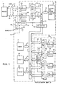
- Figs. 1 and 2 show a continuous diagrammatic representation of the logic of the present system.
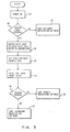
- Fig. 3 is a flow chart of the process by which each display unit work station determines whether it is a primary or secondary work station.
- Fig. 4 is a flow chart of a typical process illustrating how the primary work station controls and allocates queuing and carrying out of jobs by a combination of work stations.
- The logic for an embodiment of the present invention is shown in Figs. 1 and 2. The system comprises a printer 10 which is shared by three display
unit work stations display unit 11 is the primary display unit, i.e., all communications fromsecondary display units primary display unit 11 and themicroprocessor 14 of the primary display unit functions to control all communications with the printer including the communications fromsecondary display units primary display unit 11.Secondary display units microprocessors microprocessor 14.Primary display unit 11 contains anoperational memory 17 which includes the operational program utilized bymicroprocessor 14 in controlling the multiplexing and other operations. This memory may conveniently be a convential 32K RAM memory. Similarly,secondary display units -
Primary work station 11 also contains a serialbulk storage memory 18, conveniently a diskette memory in which a wide variety of operational and control programs may be stored and selectively loaded intooperational memory 17 viabuses main bus 21. Likewise, secondary displayunit work stations Display 22 is controlled bymicroprocessor 14 which issues and receives data fromdisplay 22 viabuses main bus 21. Standard text processing and formatting operations may be carried out usingdisplay unit 22 under control ofmicroprocessor 14. Some typical work processing and formatting operations which may be carried out using the combination ofdisplay 22 andmicroprocessor 14 are described in detail in U.S. Patents 4,137,564, 4,126,893 and 4,138,719. - In a
similar fashion microprocessors secondary work stations main buses - It should be noted that in their word processing and formatting operations, secondary display
unit work stations unit work station 11. It is only in the communication and control of the printer 10 to produce the final hard copy of the data which has been formatted in the secondary display unit that secondary displayunit work stations unit work station 11 in the manner to be hereinafter described in detail. - Display
unit work stations diskette memory 18.Microprocessors - The determination is made as follows. Where a display unit work station such as display
unit work station 11 is plugged directly into the printer and is to function as a primary display unit work station, it is connected with aconnector 27. If the display unit is to function as a secondary display unit, it is connected to the printersharing adapter unit 28 which will be described hereinafter in greater detail through connectors likeconnectors direct connector 27, it is to be noted that in addition toterminals 30 and 31 which couple transmitlines lines unit work station 11 and printer 10,terminal lines unit work station 11 are shorted vialine 40. This puts status latch 41 in primary work station at ground level. On the other hand, let us consider a connector such asconnector 29 which is not directly connected to the printer 10 but rather in the case of secondarydisplay unit station 12 connected toprinter sharing adapter 28. Likeconnector 27,connector 29 has a pair ofterminals transmit lines lines 46 and 47. However,terminals 48 and 49 inconnector 29 are not shorted to each other. Consequently, status latch 50 in secondarydiplay work station 12 will not be at ground. - Accordingly, it is the condition of this status latch by which the display unit work station microprocessor determines whether the work station is to function as a primary or as a secondary work station. In this respect, let us consider
primary work station 11. The condition of status latch 41 is transmitted tomicroprocessor 14 vialine 51 communicating throughmain bus 21 andbus 23 to themicroprocessor 14. When the status latch communicates tomicroprocessor 14 in the appropriate timing sequence (not shown) that it is at ground,microprocessor 14 communicates withdiskette memory 18 and has loaded viamain bus 21 intooperational memory 17 the selected programs which will permitmicroprocessor 14 to control the functioning of displayunit work station 11 as a primary work station. On the other hand with respect tosecondary work station 12, at the appropriate time sequence, the condition that status latch 50 is not at ground is communicated via line 52 andmain bus 25 andbus 53 tomicroprocessor 15.Microprocessor 15 thereby determines that status latch 50 is not at ground and consequently displayunit work station 12 is to function as a secondary display unit work station. Accordingly,microprocessor 15 sends appropriate commands overmain bus 25 to load programs from its associated diskette memory into its operational memory which will permit the operation ofmicroprocessor 15 to control the operation of the display unit work station as a secondary work station. - In the same manner, since display
unit work station 13 is to function as a secondary display unit work station, the condition ofconnector 54 produces a non-ground condition onstatus latch 55 andmicroprocessor 16 operates in the manner described above to set up and control the operation of displayunit work station 13 as a secondary display unit work station. - Let us now describe how communications between the primary and secondary work station and the printer are carried out. First, with respect to communications between the primary work station directly with the printer. It should be noted that in the system being described the interface between the work station and the printer is a serial interface while inside of the work station, i.e., communications to and from the microprocessor and other units involve parallel interfacing buses. Consequently, information leaving the work station to the printer must be serialized and data from the printer back to the work station must be deserialized into its initial parallel form. Let us assume that the information in
work station 11 has been formatted into its final form and we are ready to print the hard copy.Microprocessor 14 then has the final formatted information which has been stored inmemory 17 loaded ontomain bus 21 throughbuffer 56 for appropriate timing, and the data frommain bus 21 is then loaded viabus 57 toserializer 58. Then, in serial form, the data are transmitted tobuffer 59 where they await appropriate timing of clock signal (not shown) frommicroprocessor 14 to be transmitted overtransmission lines work station 11 is received in serial form overlines microprocessor 14 to be loaded intodeserializer 61 then viabus 62 back tomain bus 21 and toprocessor 14 in parallel form. - Now let us consider the operation of a secondary work station as exemplified by
work station 12. When the formatting of the information has been completed and the information is now ready to be printed on the printer, thesystem microprocessor 15 likemicroprocessor 14 communicates with the memory and has the formatted information loaded on themain bus 25 from which it proceeds viabus 63 to serializer 64 where it is serialized and transmitted vialine 65 totransmission buffer 66 and then on totransmission line 44 where it communicates throughterminal 42 andconnector 29 withline 45 ofprinter sharing adapter 28 where it is loaded into receivebuffer 66 of the adapter. The adapter then operates under appropriate timing signals from aclock pulse generator 76 containing a counter 77 and means for generating pulses at a selected rate applied todeserializeron line 78 to load the information intodeserializer 67 whereby information is deserialized and put into parallel form so that it may communicate overbus 68 tomain bus 21 ofprimary work station 11. - Then, under the control of the
microprocessor 14 ofprimary work station 11, the information at the appropriate timing is applied toserializer 58 and then to transmitbuffer 59 from which it is tranmsmitted to the printer in the same manner previously described with respect to data originating in theprimary work station 11. In a similar fashion, communications from the printer 10 back tosecondary work station 12 are handled in the following manner throughlines main bus 21 and frombus 21 throughbus 69 for theprinter sharing adapter 28 to serializer 70 where the information is serialized. Then the data goes to transmitbuffer 71 inprinter sharing adapter 28 from which it is sent vialine 46 back to receivebuffer 72 ofsecondary work station 12. Then, the information is loaded overline 73 to deserializer 74, and then in parallel form on tobus 75 communicating withmain bus 25 back to secondarywork station microprocessor 15. - It may be readily observed that communication with printer 10 to and from
secondary work station 13 is carried out in a similar manner throughprinter sharing adapter 28. - We have now described how the system functions in the multiplexing control of the processor in the primary work station, let us now consider some of the operations carried on by the system. With reference to the flow chart of Fig. 3, we will now describe the process through which each of the work stations will go during its initialization or "power on" routine in order to determine whether or not it is a primary or secondary work station and to accordingly activate its inactive logic and memory in order to selectively operate as a primary or secondary work station. After the start of the equipment, power is turned on, block 79. Then, a determination is made, block 80 as to whether or not the display unit work station is attached directly to the printer. As previously described in detail, this involves determining the condition of its status latch, i.e., latches 41, 50 or 55 in the respective work stations in Figs. 1 and 2. If the printer is not directly attached, then (block 87) selective programs are loaded into the work station operational memory which will control the microprocessor of the work station to operate the work station as a secondary work station. On the other hand, if the printer cable is attached, then we know that the work station is a primary work station or a stand-alone work station.
- A determination has to be made as to whether it is a stand-alone work station or whether it is to control printer sharing with a plurality of secondary work stations, and the primary work station. This is determined by instituting a routine controlled by the
microprocessor 14 of the primary work station which will determine whether there are secondary work stations and a printer sharing adapter attached to the work station. This routine involves the following steps. Themicroprocessor 14 of the primary work station communicates with theclock pulse generator 76 onprinter sharing adapter 28 to set up appropriate timing for printer sharing. The clock pulse generator rate on the sharing card is set, block 82, and begins to operate. Then, block 83, themicroprocessor 14 determines whether a count exists in counter 77 ofclock pulse generator 76, i.e., (block 84) is the counter running? In other words, is there a clock pulse generator which has a counter? In effect, this determines whether or not aprinter sharing adapter 28 is attached. If there is no printer sharing adapter attached, then there would be no counter and it would not be running. Consequently, block 85,microprocessor 14 will load appropriate software fromdiskette 18 into itsmemory 17 to permit its operation as a stand alone work station. - On the other hand, if it is determined that the counter is running, i.e., there is a counter, then, this would be an indication that there are secondary work stations and, block 86, software from
diskette 18 would be loaded intooperational memory 17 which would permitmicroprocessor 14 to operatework station 11 as a primary work station controlling the multiple communication of secondary work stations to printer 10. - Now with respect to the flow chart of Fig. 4, we will describe a simple operation wherein the primary work station coordinates the job activity of all the
work stations secondary work stations primary work station 11. Therefore, in describing a typical job operation, we will describe the interaction between theprimary work station 11 andsecondary work station 12. The interaction betweenprimary work station 11 andsecondary work station 13 will be substantially identical. When the secondary work station requires the printer, it sends arequest printer inquiry 87 overchannel 88 to theprimary work station 11. In response, theprimary work station 11 sends a queue position, block 89, back to the secondary work station overchannel 90 and increments to the next queue position. Having received its queue position, thesecondary work station 12 waits for its turn in the following manner. - The primary work station continuously broadcasts the next positions in the queue as they are reached, block 91. This is communicated back to the secondary work station over
channel 92. It should be noted the term "channels" indicate command flow. Actual communication is accomplished through the serializers/deserializers illustrated in Figs. 1 and 2. In the mean time, secondary work station waits for the receipt of each subsequent job number, block 93. When a job number arrives, secondary work station makes a determination as to whether its queue number is equivalent to the job number,decision block 94. If it is not, it cycles back todecision block 94 and continues to wait for the next job number. When the job number is equal the queue number, secondary work station acknowledges that the job number is this work stations position in the queue, block 95, back to the primary work station overchannel 96. In the mean time, primary work station, block 97, is awaiting an acknowledgement of printer ownership, i.e., that the secondary work station's position in the queue has been reached. When this ownership is not acknowledged,decision block 98, primary work station loops back to block 91 and broadcasts the next position in the queue. - On the other hand, as in the present case, when such an acknowledgement is received by the primary work station, the printer is allocated to the work station that has responded, i.e., in the present case
secondary work station 12,block 99. Having thus obtained control over the printer, thesecondary work station 12 proceeds to carry out all of its jobs, block 100. Until all the jobs are completed as determined bydecision block 101, the secondary work station retains control of the printer. Upon the completion of the jobs, secondary work station releases the printer, block 102, which is communicated back to the primary work station overchannel 103. At this point, the primary work station acknowledges back to the secondary work station that is has released the printer overchannel 104, and proceeds to deal- locate the printer, block 105, from the secondary work station. The primary work station then loops back to block 91 where the next position in the queue is again repetitively broadcast, and the process is continued until the next broadcast position coincides with a queue position of one of the work stations or the queue is empty. - It should be noted that the queueing procedure described above involving the coaction of the primary and secondary work station is also carried out in the primary work station when all jobs and sub-tasks involve only the primary work station.
- While the invention has been particularly shown and described with reference to a preferred embodiment it will be understood by those skilled in the art that various other changes in form and detail may be made without departing from the scope of the claims.
Claims (8)
Applications Claiming Priority (2)
| Application Number | Priority Date | Filing Date | Title |
|---|---|---|---|
| US24796981A | 1981-03-26 | 1981-03-26 | |
| US247969 | 1981-03-26 |
Publications (3)
| Publication Number | Publication Date |
|---|---|
| EP0061571A2 EP0061571A2 (en) | 1982-10-06 |
| EP0061571A3 EP0061571A3 (en) | 1983-03-30 |
| EP0061571B1 true EP0061571B1 (en) | 1985-06-19 |
Family
ID=22937103
Family Applications (1)
| Application Number | Title | Priority Date | Filing Date |
|---|---|---|---|
| EP82100970A Expired EP0061571B1 (en) | 1981-03-26 | 1982-02-10 | Word processing system with a printer shared by a plurality of display units |
Country Status (5)
| Country | Link |
|---|---|
| EP (1) | EP0061571B1 (en) |
| JP (1) | JPS57164328A (en) |
| CA (1) | CA1169576A (en) |
| DE (1) | DE3264165D1 (en) |
| MY (1) | MY8800019A (en) |
Families Citing this family (5)
| Publication number | Priority date | Publication date | Assignee | Title |
|---|---|---|---|---|
| JPS58123135A (en) * | 1982-01-19 | 1983-07-22 | Silver Seiko Ltd | Electronic typewriter |
| DE3484744D1 (en) * | 1983-05-11 | 1991-08-01 | Ibm | DATA AND TEXT PROCESSING SYSTEM WITH TERMINAL STATIONS DOUBLE EMULATION CAPABILITY. |
| JP2545770B2 (en) * | 1984-01-12 | 1996-10-23 | 富士ゼロックス株式会社 | Electronic printer |
| NL8501888A (en) * | 1985-07-01 | 1986-04-01 | Oce Nederland Bv | OFFICE AUTOMATION SYSTEM. |
| JPH0621976B2 (en) * | 1985-08-20 | 1994-03-23 | 松下電器産業株式会社 | Switching device between input editing device and printing device |
Family Cites Families (3)
| Publication number | Priority date | Publication date | Assignee | Title |
|---|---|---|---|---|
| US3950731A (en) * | 1973-12-26 | 1976-04-13 | General Electric Company | Data processing arrangement for printers |
| US4150429A (en) * | 1974-09-23 | 1979-04-17 | Atex, Incorporated | Text editing and display system having a multiplexer circuit interconnecting plural visual displays |
| JPS55138141A (en) * | 1979-04-17 | 1980-10-28 | Toshiba Corp | Printer share mechanism |
-
1981
- 1981-12-18 JP JP56203787A patent/JPS57164328A/en active Granted
-
1982
- 1982-01-05 CA CA000393603A patent/CA1169576A/en not_active Expired
- 1982-02-10 EP EP82100970A patent/EP0061571B1/en not_active Expired
- 1982-02-10 DE DE8282100970T patent/DE3264165D1/en not_active Expired
-
1988
- 1988-12-30 MY MY19/88A patent/MY8800019A/en unknown
Also Published As
| Publication number | Publication date |
|---|---|
| EP0061571A2 (en) | 1982-10-06 |
| JPS57164328A (en) | 1982-10-08 |
| MY8800019A (en) | 1988-12-31 |
| CA1169576A (en) | 1984-06-19 |
| DE3264165D1 (en) | 1985-07-25 |
| JPS6248250B2 (en) | 1987-10-13 |
| EP0061571A3 (en) | 1983-03-30 |
Similar Documents
| Publication | Publication Date | Title |
|---|---|---|
| EP0279558A1 (en) | System of data working stations for teaching a class of students | |
| EP0079468B1 (en) | Direct memory access method for use with a multiplexed data bus | |
| JPS6126102B2 (en) | ||
| JPH0675894A (en) | Method for transmitting signal and data | |
| US4811284A (en) | Computer terminal system with memory shared between remote devices | |
| US4525806A (en) | Printer sharing by plurality of display units in word processing system | |
| EP0100655B1 (en) | Data flow control system | |
| US5245705A (en) | Functional addressing method and apparatus for a multiplexed data bus | |
| EP0061571B1 (en) | Word processing system with a printer shared by a plurality of display units | |
| Ossanna et al. | Communications and input/output switching in a multiplex computing system | |
| JPS58502027A (en) | Peripherals adapted to monitor low data rate serial input/output interfaces | |
| US4977499A (en) | Method and apparatus for commanding operations on a computer network | |
| US4371950A (en) | Peripheral control interface circuit for train printer-data link processor | |
| US4357681A (en) | Line turn circuit for data link | |
| US4371948A (en) | Train printer-data link processor | |
| JP3223050B2 (en) | Printing device | |
| US4370730A (en) | Ram buffer memory circuit system for train printer-data link processor | |
| EP0080369B1 (en) | Peripheral unit adapted to monitor a low data rate serial input/output interface | |
| EP0055741B1 (en) | Input/output system and method of communication for peripheral devices in data processing system | |
| EP0076408B1 (en) | Functional addressing method for a multiplexed data bus | |
| US5398233A (en) | Method of resetting coupled modules and system using the method | |
| EP0055763B1 (en) | Input/output processor and method of communication for data processing system | |
| JPS62286152A (en) | Controller for input and output device | |
| JP3399776B2 (en) | Computer and method for transferring peripheral device control data in computer | |
| CA1228676A (en) | Computer terminal system with memory shared between remote devices |
Legal Events
| Date | Code | Title | Description |
|---|---|---|---|
| PUAI | Public reference made under article 153(3) epc to a published international application that has entered the european phase |
Free format text: ORIGINAL CODE: 0009012 |
|
| AK | Designated contracting states |
Designated state(s): DE FR GB IT |
|
| PUAL | Search report despatched |
Free format text: ORIGINAL CODE: 0009013 |
|
| AK | Designated contracting states |
Designated state(s): DE FR GB IT |
|
| 17P | Request for examination filed |
Effective date: 19830121 |
|
| ITF | It: translation for a ep patent filed |
Owner name: IBM - DR. ALFREDO BRAVI |
|
| GRAA | (expected) grant |
Free format text: ORIGINAL CODE: 0009210 |
|
| AK | Designated contracting states |
Designated state(s): DE FR GB IT |
|
| REF | Corresponds to: |
Ref document number: 3264165 Country of ref document: DE Date of ref document: 19850725 |
|
| ET | Fr: translation filed | ||
| PLBE | No opposition filed within time limit |
Free format text: ORIGINAL CODE: 0009261 |
|
| STAA | Information on the status of an ep patent application or granted ep patent |
Free format text: STATUS: NO OPPOSITION FILED WITHIN TIME LIMIT |
|
| 26N | No opposition filed | ||
| ITTA | It: last paid annual fee | ||
| PGFP | Annual fee paid to national office [announced via postgrant information from national office to epo] |
Ref country code: GB Payment date: 19950125 Year of fee payment: 14 |
|
| PGFP | Annual fee paid to national office [announced via postgrant information from national office to epo] |
Ref country code: FR Payment date: 19950128 Year of fee payment: 14 |
|
| PGFP | Annual fee paid to national office [announced via postgrant information from national office to epo] |
Ref country code: DE Payment date: 19950223 Year of fee payment: 14 |
|
| PG25 | Lapsed in a contracting state [announced via postgrant information from national office to epo] |
Ref country code: GB Effective date: 19960210 |
|
| GBPC | Gb: european patent ceased through non-payment of renewal fee |
Effective date: 19960210 |
|
| PG25 | Lapsed in a contracting state [announced via postgrant information from national office to epo] |
Ref country code: FR Effective date: 19961031 |
|
| PG25 | Lapsed in a contracting state [announced via postgrant information from national office to epo] |
Ref country code: DE Effective date: 19961101 |
|
| REG | Reference to a national code |
Ref country code: FR Ref legal event code: ST |