EP0061569B1 - Socket end - Google Patents
Socket end Download PDFInfo
- Publication number
- EP0061569B1 EP0061569B1 EP82100815A EP82100815A EP0061569B1 EP 0061569 B1 EP0061569 B1 EP 0061569B1 EP 82100815 A EP82100815 A EP 82100815A EP 82100815 A EP82100815 A EP 82100815A EP 0061569 B1 EP0061569 B1 EP 0061569B1
- Authority
- EP
- European Patent Office
- Prior art keywords
- sleeve
- section
- ring
- longitudinal
- stiffening sleeve
- Prior art date
- Legal status (The legal status is an assumption and is not a legal conclusion. Google has not performed a legal analysis and makes no representation as to the accuracy of the status listed.)
- Expired
Links
- 230000008878 coupling Effects 0.000 claims abstract 6
- 238000010168 coupling process Methods 0.000 claims abstract 6
- 238000005859 coupling reaction Methods 0.000 claims abstract 6
- 229920001971 elastomer Polymers 0.000 description 11
- 239000004033 plastic Substances 0.000 description 5
- 229920003023 plastic Polymers 0.000 description 5
- 238000006073 displacement reaction Methods 0.000 description 4
- 238000007789 sealing Methods 0.000 description 4
- 239000010935 stainless steel Substances 0.000 description 4
- 230000002787 reinforcement Effects 0.000 description 3
- 241000209035 Ilex Species 0.000 description 2
- 238000004873 anchoring Methods 0.000 description 2
- 239000011324 bead Substances 0.000 description 2
- 239000002131 composite material Substances 0.000 description 2
- 239000000806 elastomer Substances 0.000 description 2
- 230000009191 jumping Effects 0.000 description 2
- 230000006641 stabilisation Effects 0.000 description 2
- 238000011105 stabilization Methods 0.000 description 2
- 229910000831 Steel Inorganic materials 0.000 description 1
- 230000001771 impaired effect Effects 0.000 description 1
- 210000001503 joint Anatomy 0.000 description 1
- 238000004519 manufacturing process Methods 0.000 description 1
- 239000000463 material Substances 0.000 description 1
- 238000000034 method Methods 0.000 description 1
- 239000002990 reinforced plastic Substances 0.000 description 1
- 239000010959 steel Substances 0.000 description 1
Images
Classifications
-
- F—MECHANICAL ENGINEERING; LIGHTING; HEATING; WEAPONS; BLASTING
- F16—ENGINEERING ELEMENTS AND UNITS; GENERAL MEASURES FOR PRODUCING AND MAINTAINING EFFECTIVE FUNCTIONING OF MACHINES OR INSTALLATIONS; THERMAL INSULATION IN GENERAL
- F16L—PIPES; JOINTS OR FITTINGS FOR PIPES; SUPPORTS FOR PIPES, CABLES OR PROTECTIVE TUBING; MEANS FOR THERMAL INSULATION IN GENERAL
- F16L21/00—Joints with sleeve or socket
- F16L21/002—Sleeves or nipples for pipes of the same diameter; Reduction pieces
- F16L21/005—Sleeves or nipples for pipes of the same diameter; Reduction pieces made of elastic material, e.g. partly or completely surrounded by clamping devices
-
- F—MECHANICAL ENGINEERING; LIGHTING; HEATING; WEAPONS; BLASTING
- F16—ENGINEERING ELEMENTS AND UNITS; GENERAL MEASURES FOR PRODUCING AND MAINTAINING EFFECTIVE FUNCTIONING OF MACHINES OR INSTALLATIONS; THERMAL INSULATION IN GENERAL
- F16L—PIPES; JOINTS OR FITTINGS FOR PIPES; SUPPORTS FOR PIPES, CABLES OR PROTECTIVE TUBING; MEANS FOR THERMAL INSULATION IN GENERAL
- F16L25/00—Constructive types of pipe joints not provided for in groups F16L13/00 - F16L23/00 ; Details of pipe joints not otherwise provided for, e.g. electrically conducting or insulating means
- F16L25/14—Joints for pipes of different diameters or cross-section
Definitions
- the invention relates to a sleeve of the type mentioned in the preamble of claim 1.
- Sockets of this type are used in particular, but not exclusively, for the repair of pipelines.
- such sleeves can be used wherever two sleeveless pipe ends, so-called spigot ends, which are arranged at least substantially coaxially to one another, are to be tightly connected to one another with a butt joint.
- a sleeve of the type mentioned is known from the document DE-C-1 281 759.
- the known sleeve consists of a rubber sleeve for receiving the two pipe ends to be connected to one another, an axially slotted plastic sleeve surrounding the sleeve on the outside and tensioning straps which are inserted between radial guide ribs so that they are secured against axial displacement.
- the sleeve has a total of two straps, which are each arranged directly on the edge of the sleeve.
- the respective axially outer guide rib for the tensioning band is designed as a radial web projecting radially outward on the outer edge of the sleeve in the manner of a flange.
- the rubber sleeve is axially fixed in the sleeve in that the axially slotted sleeve edge alternately has radially inwardly and radially outwardly bent web sections.
- the radially downwardly curved web sections serve to axially fix the rubber sleeve in that they engage in front of the end faces of the sleeve in the manner of a stop ring.
- the radially outwardly bent web sections serve as a guide or anchoring for the tensioning straps and prevent them from jumping off axially outward from the essentially barrel-shaped sleeve.
- the radially inwardly curved web sections of the known sleeve described above cannot prevent the cuff from jumping over the inner edge of the bent web sections even at the slightest radially inward deformation and thus losing its fixation.
- the sleeve is therefore susceptible to unauthorized and unintentional removal of the sleeve from the sleeve.
- a significantly better axial fixation of the sleeve and the cuff against one another is achieved with the sleeve known from the documents DE-U-7 037 and DE-C-2 109 566.
- the outer edge areas of the rubber sleeve encompass the two opposite outer edges of the sleeve and are forced onto the outside of the sleeve by the tensioning straps.
- a disadvantage of this arrangement is that the tensioning straps "float", ie. H. do not transfer the clamping force required to ensure the tightness of the sleeve directly to the rigid sleeve and from there to the sealing area of the rubber sleeve, but instead act in a damped and buffered manner on the outer jacket of the sleeve.
- the invention has for its object to provide a sleeve of the type mentioned, in which the sleeve and the sleeve are connected to an axially sufficiently stabilized unit in particular, without the need for an excessive use of elastomer, and in which the straps rest directly on the outer surface of the sleeve.
- the invention thus creates a sleeve consisting of a sleeve, sleeve and tensioning straps, in which the radially outwardly projecting radial web on the sleeve edge does not serve to guide the tensioning straps, but rather serves to axially fixate and improve the overall rigidity of the sleeve by virtue of the fact that this radial web extends from the outer edges the cuff is encompassed, in particular in such a way that the radial web is reinforced by a ring-like Section of the sleeve is gripped axially.
- this ring section of the cuff preferably has an at least substantially circular or square cross section, more precisely a cord cross section.
- the inner ring diameter of this ring section of the cuff is preferably further dimensioned such that it encloses the sleeve under radial prestress.
- the sleeve of the invention also forms a fixed structural unit without tensioning straps, in which in particular the sleeve and the sleeve are fixed axially firmly against one another.
- the sleeve can be easily transported, handled and used to produce the pipe connections without the risk of changing the axial nominal position of the sleeve and the sleeve.
- the bond between the sleeve and sleeve is also particularly inexpensive to manufacture, d. H. pre-assembled. To produce this composite, the tensioning straps do not need to be put on or even pulled into closed guides, nor does the sleeve edge need to be deformed during the pre-assembly of the sleeve.
- the cuff is preferably made of conventional rubber qualities, but can also be easily made from appropriate plastics, as long as the application specifications allow.
- the tensioning straps consist in particular of steel, especially corrosion-resistant steel, or of tensile plastics, or corresponding composite materials.
- the tensioning means used for tensioning the tensioning straps are of a common type and are known in large numbers, so that their detailed explanation within the scope of the invention is omitted.
- the sleeve preferably consists of a material which, on the one hand, gives the sleeve sufficient dimensional stability, but, on the other hand, retains the deformability required to bridge tolerances and roundness of the pipe ends to be connected. From these points of view, the sleeve preferably consists of corrosion-resistant steel sheet or of plastic, in particular reinforced plastic.
- the sleeve has annular, radially outwardly projecting guide ribs, which are integrally formed on the sleeve or formed from it.
- the tensioning straps are inserted between these guide ribs.
- the axially outermost guide rib is located so far axially inward from the outer edge of the sleeve that the distance between the inner edge of the radial web on the sleeve edge and the axially outer edge of this guide rib is at least approximately the same size as the axial width of the annular portion of the sleeve.
- the sleeve preferably has axial incisions which extend axially inward from the outer edge of the sleeve, namely to below the tensioning straps, preferably to an axial depth which extends axially inward beyond the tensioning straps.
- These incisions serve the purpose of being able to absorb large and very large deviations of the actual outside diameter of the pipe ends to be connected from the nominal diameters and also of greater roundness of the pipe ends without impairing the tightness of the pipe connection.
- a further adaptability to deviations in the dimensions of the pipe ends to be connected from given nominal dimensions with simultaneous further stabilization of the sleeve and a noticeable pre-assembly and assembly ease is achieved if the sleeve is not cylindrically closed, but is designed as an open band, according to one embodiment of the invention
- Ends overlap in the area of a tongue formed on one of the two ends, the axial width of which is dimensioned such that the tongue runs between two tensioning straps arranged in the edge areas, without getting under a tensioning strap at any point.
- the formed tongue, with which the open sleeve band overlaps, is therefore narrower in the axial direction than the inner edge spacing between the two annular guide ribs for the tensioning bands lying opposite one another in the outer edge regions of the sleeve.
- a sleeve 1 of the sleeve of the invention is an at least substantially cylindrical sleeve made of corrosion-resistant steel sheet.
- the outer edges of the sleeve are flanged to form a radial web 2 for anchoring a sleeve radially outward.
- the radial web 2 is adjoined by a smooth cylindrical section 3 of the jacket of the sleeve 1, which serves to receive a ring-like reinforcement of the sleeve pulled around the radial web 2.
- the cylindrical sleeve section 3 is delimited by one of two annular guide ribs 4, which are designed as radially projecting beads. Between the two annular guide ribs 4, 4, a smooth cylindrical sleeve section 5 is again formed, the axial width of which at least substantially corresponds to the width of a tensioning band to be inserted between the two guide ribs 4.
- the sleeve 1 also has an equal angular distance from one another over its entire circumference, a series of axial slots 6 which extend axially inward from the outer edge 7 of the sleeve 1 to behind the second annular guide rib 4. These axial slots 6 enable the tensioning straps which are placed around the sleeve 1 in the cylindrical sections 5 to bring about a reduction in the diameter of the sleeve 1 when tightening. This serves to generate a radially inward contact pressure on the internal rubber sleeve for sealing purposes.
- FIG. 2 In contrast to the exemplary embodiment of a sleeve of the sleeve shown in FIG. 1, an end of a sleeve 1 designed as an open band is shown in plan view in FIG. 2.
- the sleeve 1 again consists of corrosion-resistant steel sheet.
- the sleeve 1 are designed to be substantially wider than in the embodiment shown in FIG. 1 and have the same width as the web-like or finger-like sleeve sections that remain between two successive slots, which essentially consist of the radial web 2, the first cylindrical section 3, the two Guide ribs 4 and the cylindrical portion 5 formed between these two guide ribs.
- a tongue 8 is formed which, based on the band forming the sleeve, extends axially and, based on the cylindrical sleeve, in the circumferential direction so far that it Even with the largest permissible circumference of the sleeve for stabilization, the opposite end of the band overlaps sufficiently, preferably in particular radially inside, seen from the outside so that it overlaps the opposite end.
- the width of the tongue 8 is dimensioned such that it is narrower than the distance between the two axially innermost guide ribs 4, 4 'from one another. This ensures that the tongue is not impaired in its displaceability and mobility in the circumferential direction by the tightened tensioning straps which lie in the cylindrical sections 5. Such mobility promotes assembly security and facilitates the assembly process.
- FIG. 3 An embodiment of the complete sleeve of the invention is shown in axial section and in partial representation in FIG. 3.
- the sleeve 1 is made of plastic and has on its outer edge a flange-shaped radial web 2.
- the sleeve 9 surrounds with its outer edge 10 the outer wheel 7 and the radial web 2 of the sleeve 1, in such a way that an annular reinforcement 11 formed on the outer edge 10 of the sleeve 9 engages behind the annular web 2 from the inside axially.
- the ring web 2 is clamped axially between the outer edge 10 and the ring section 11 of the sleeve 9.
- the ring section 11 of the sleeve 9 also has a radial prestress.
- the ring portion 11 of the sleeve 9 has a substantially square cross-section with strongly rounded edges.
- the ring section 11 is dimensioned such that a considerable force is required to radially expand the ring section 11.
- a tensioning band 12 is inserted, secured against axial displacement, which can be tensioned by means of schematically indicated tensioning means 13 in the sense of a radius reduction.
- the radially inward force generated by this reduction in radius is transmitted directly to the cylindrical section 5 of the sleeve 1 and from this sleeve 1 to the sleeve 9 and to sealing elements 14 formed thereon, which seal the inner jacket of the sleeve against the outer jacket of an inserted pipe end.
- the sealing elements 14 are shown in the exemplary embodiment shown here as simple bead rings. In practice, of course, they can also have any other shape, in particular also be lip-shaped.
Landscapes
- Engineering & Computer Science (AREA)
- General Engineering & Computer Science (AREA)
- Mechanical Engineering (AREA)
- Clamps And Clips (AREA)
- Joints With Sleeves (AREA)
- Mutual Connection Of Rods And Tubes (AREA)
- Glass Compositions (AREA)
- Semiconductor Lasers (AREA)
- Crystals, And After-Treatments Of Crystals (AREA)
- Protection Of Pipes Against Damage, Friction, And Corrosion (AREA)
Abstract
Description
Die Erfindung betrifft eine Muffe der im Oberbegriff des Anspruchs 1 genannten Art.The invention relates to a sleeve of the type mentioned in the preamble of
Muffen dieser Art werden insbesondere, jedoch nicht ausschließlich zur Reparatur von Rohrleitungen verwendet. Generell sind solche Muffen überall dort einsetzbar, wo zwei zumindest im wesentlichen koaxial zueinander angeordnete muffenlose Rohrenden, sogenannte Spitzenden, unter Stirnstoß dicht miteinander verbunden werden sollen.Sockets of this type are used in particular, but not exclusively, for the repair of pipelines. In general, such sleeves can be used wherever two sleeveless pipe ends, so-called spigot ends, which are arranged at least substantially coaxially to one another, are to be tightly connected to one another with a butt joint.
Eine Muffe der eingangs genannten Art ist aus der Druckschrift DE-C-1 281 759 bekannt. Die bekannte Muffe besteht aus einer Gummimanschette zur Aufnahme der beiden miteinander zu verbindenden Rohrenden, einer die Manschette außen umschließenden axial geschlitzten Kunststoffhülse und Spannbändern, die zwischen radialen Führungsrippen eingelegt sind, so daß sie gegen eine axiale Verschiebung gesichert sind. Die Muffe weist insgesamt zwei Spannbänder auf, die jeweils unmittelbar am Rand der Hülse angeordnet sind. Die jeweils axial äußere Führungsrippe für das Spannband ist als unmittelbar am äußeren Rand der Hülse flanschartig nach radial außen vorspringender Radialsteg ausgebildet. Bei zusammengesetzter Muffe ist die Gummimanschette durch einen axial zentral angeordneten Ringnut-Ringfeder-Eingriff gegen eine axiale Verschiebung und damit gegen ein Herausfallen aus der Hülse gesichert. Diese Art der axialen Fixierung der Gummimanschette ist unzureichend. Bei nicht gespannten Spannbändern und nicht vorgespannter Hülse besteht die Gefahr, daß die retativ lose in der Hülse liegende Manschette aus dieser herausfällt und verloren geht. Die Handhabung der Muffe als Einheit wird dadurch beeinträchtigt. Mindestens ebensogroß ist jedoch die Gefahr einer axialen Verschiebung der Hülse und der Manschette gegeneinander beim Herstellen der Rohrverbindung. Eine genaue axiale Relativfixierung zwischen der Hülse und der Muffe ist jedoch für eine zuverlässige Dichtheit der Muffe eine unabdingbare Voraussetzung.A sleeve of the type mentioned is known from the document DE-C-1 281 759. The known sleeve consists of a rubber sleeve for receiving the two pipe ends to be connected to one another, an axially slotted plastic sleeve surrounding the sleeve on the outside and tensioning straps which are inserted between radial guide ribs so that they are secured against axial displacement. The sleeve has a total of two straps, which are each arranged directly on the edge of the sleeve. The respective axially outer guide rib for the tensioning band is designed as a radial web projecting radially outward on the outer edge of the sleeve in the manner of a flange. When the sleeve is assembled, the rubber sleeve is secured against axial displacement and thus against falling out of the sleeve by an axially centrally arranged annular groove-ring spring engagement. This type of axial fixation of the rubber sleeve is insufficient. In the case of non-tensioned tensioning straps and a non-prestressed sleeve, there is a risk that the sleeve lying loosely in the sleeve will fall out of it and be lost. This affects the handling of the sleeve as a unit. However, the danger of an axial displacement of the sleeve and the sleeve relative to one another when producing the pipe connection is at least as great. An exact axial relative fixation between the sleeve and the sleeve is an essential prerequisite for reliable tightness of the sleeve.
Bei der aus der Druckschrift DE-B-1 211 045 bekannten Muffe erfolgt die axiale Fixierung der Gummimanschette in der Hülse dadurch, daß der axial geschlitzte Muffenrand abwechselnd radial einwärts und radial auswärts aufgebogene Stegabschnitte aufweist. Die radial abwärts gebogenen Stegabschnitte dienen der axialen Fixierung der Gummimanschette dadurch, daß sie nach Art eines Anschlagringes vor die Stirnflächen der Manschette greifen. Die radial auswärts aufgebogenen Stegabschnitte dienen als Führung oder Anschiag für die Spannbänder und verhindern, daß diese nach axial auswärts von der im wesentiichen tonnenförmigen Hülse abspringen.In the sleeve known from the document DE-B-1 211 045, the rubber sleeve is axially fixed in the sleeve in that the axially slotted sleeve edge alternately has radially inwardly and radially outwardly bent web sections. The radially downwardly curved web sections serve to axially fix the rubber sleeve in that they engage in front of the end faces of the sleeve in the manner of a stop ring. The radially outwardly bent web sections serve as a guide or anchoring for the tensioning straps and prevent them from jumping off axially outward from the essentially barrel-shaped sleeve.
Durch die radial einwärts gebogenen Stegabschnitte der vorstehend beschriebenen bekannten Muffe kann jedoch nicht verhindert werden, daß die Manschette bereits bei der geringsten radial einwärts gerichteten Verformung über den Innenrand der umgebogenen Stegabschnitte hinausspringt und damit ihre Fixierung verliert. Die Muffe ist damit gegen unbefugtes und unbeabsichtigtes Entfernen der Manschette aus der Hülse anfällig. Außerdem ist bei dieser Ausgestaltung der axialen Fixierung der Manschette in der Hülse auch nicht gewährleistet, daß bei der Herstellung der Rohrverbindung die einwärts gebogenen Stegabschnitte der Hülse an beiden Seiten wirklich bestimmungsgemäß gleich über die Stirnseiten der Manschette greifen und damit die vorbestimmte axiale Lage der Manschette und der Hülse zueinander eingehalten wird.However, the radially inwardly curved web sections of the known sleeve described above cannot prevent the cuff from jumping over the inner edge of the bent web sections even at the slightest radially inward deformation and thus losing its fixation. The sleeve is therefore susceptible to unauthorized and unintentional removal of the sleeve from the sleeve. In addition, with this configuration of the axial fixation of the sleeve in the sleeve, it is also not guaranteed that when the pipe connection is made, the inwardly bent web sections of the sleeve on both sides really fit the intended purpose directly over the end faces of the sleeve and thus the predetermined axial position of the sleeve and the sleeve is adhered to each other.
Eine deutlich bessere axiale Fixierung der Hüise und der Manschette gegeneinander wird bei der aus den Druckschriften DE-U-7 037 und DE-C-2 109 566 bekannten Muffe erreicht. Au- ßenrandbereiche der Gummimanschette umgreifen die beiden einander gegenüberliegenden Außenränder der Hülse und werden durch die Spannbänder auf die Außenseite der Hülse gezwungen. Nachteilig bei dieser Anordnung ist, daß die Spannbänder »schwimmen«, d. h. ihre zur Dichtheit der Muffe erforderliche Spannkraft nicht direkt auf die formsteife Hülse und von dieser auf den Dichtungsbereich der Gummimanschette übertragen, sondern bereits gedämpft und gepuffert auf den Außenmantel der Hülse einwirken. Die mit dieser Muffe herstellbaren Rohrverbindungen verlieren damit an Sicherheit. Außerdem müssen, um ausreichende Radialkräfte aufzubringen, wesentlich stärkere Spannbänder, insbesondere aufwendigere Spannelemente für die Spannbänder, eingesetzt werden. Schließlich erfordert die aus den genannten Druckschriften bekannte Muffe in beiden Versionen einen relativ großen Einsatz an kostenaufwendigem Elastomer.A significantly better axial fixation of the sleeve and the cuff against one another is achieved with the sleeve known from the documents DE-U-7 037 and DE-C-2 109 566. The outer edge areas of the rubber sleeve encompass the two opposite outer edges of the sleeve and are forced onto the outside of the sleeve by the tensioning straps. A disadvantage of this arrangement is that the tensioning straps "float", ie. H. do not transfer the clamping force required to ensure the tightness of the sleeve directly to the rigid sleeve and from there to the sealing area of the rubber sleeve, but instead act in a damped and buffered manner on the outer jacket of the sleeve. The pipe connections that can be made with this sleeve thus lose safety. In addition, in order to apply sufficient radial forces, much stronger tensioning straps, in particular more complex tensioning elements for the tensioning straps, must be used. Finally, the sleeve known from the cited documents requires a relatively large amount of costly elastomer in both versions.
Angesichts dieses Standes der Technik liegt der Erfindung die Aufgabe zugrunde, eine Muffe der eingangs genannten Art zu schaffen, bei der die Manschette und die Hülse zu einer insbesondere axial ausreichend stabilisierten Einheit verbunden sind, ohne daß es hierzu eines übergroßen Einsatzes an Elastomer bedarf, und bei der die Spannbänder direkt auf der Außenfläche der Hülse aufliegen.In view of this prior art, the invention has for its object to provide a sleeve of the type mentioned, in which the sleeve and the sleeve are connected to an axially sufficiently stabilized unit in particular, without the need for an excessive use of elastomer, and in which the straps rest directly on the outer surface of the sleeve.
Zur Lösung dieser Aufgabe wird eine Muffe der im Oberbegriff des Anspruchs 1 genannten Art geschaffen, die erfindungsgemäß die im kennzeichnenden Teil des Anspruchs 1 genannten Merkmale aufweist.To solve this problem, a sleeve of the type mentioned in the preamble of
Die Erfindung schafft also eine aus Manschette, Hülse und Spannbändern bestehende Muffe, bei der der radial nach außen vorspringende Radialsteg am Hülsenrand nicht der Führung der Spannbänder, sondern der axialen Fixierung und der Verbesserung der Gesamtsteifigkeit der Muffe dadurch dient, daß dieser Radialsteg von den Außenrändern der Manschette umgriffen wird, und zwar insbesondere in der Weise, daß der Radialsteg von einem ringartigen verstärkten Abschnitt der Manschette axial einspannend hintergriffen wird. Entscheidend ist dabei, daß der Ringabschnitt der Manschette nur unter Aufbringung einer signifikanten radial auswärts gerichteten Dehnkraft nach axial auswärts über den Radialsteg der Hülse gezogen werden kann. Die im konkreten Einzelfall jeweils gewünschte und benötigte Rückstellkraft des Ringabschnittes kann dabei in gebräuchlicher Weise durch eine entsprechende Dimensionierung der ringartigen Verstärkung eingestellt werden. Vorzugsweise weist dieser Ringabschnitt der Manschette aus diesem Grunde einen zumindest im wesentlichen kreisrunden oder quadratischen Querschnitt, genauer gesagt Schnurquerschnitt, auf. Der innere Ringdurchmesser dieses Ringabschnittes der Manschette ist vorzugsweise weiterhin so bemessen, daß er die Hülse unter radia-Ier Vorspannüng umschließt.The invention thus creates a sleeve consisting of a sleeve, sleeve and tensioning straps, in which the radially outwardly projecting radial web on the sleeve edge does not serve to guide the tensioning straps, but rather serves to axially fixate and improve the overall rigidity of the sleeve by virtue of the fact that this radial web extends from the outer edges the cuff is encompassed, in particular in such a way that the radial web is reinforced by a ring-like Section of the sleeve is gripped axially. It is crucial here that the ring section of the sleeve can only be pulled axially outward over the radial web of the sleeve with the application of a significant radially outward expansion force. The restoring force of the ring section that is desired and required in each individual case can be adjusted in the customary manner by appropriately dimensioning the ring-like reinforcement. For this reason, this ring section of the cuff preferably has an at least substantially circular or square cross section, more precisely a cord cross section. The inner ring diameter of this ring section of the cuff is preferably further dimensioned such that it encloses the sleeve under radial prestress.
Die Muffe der Erfindung bildet auf diese Weise auch ohne Spannbänder eine feste Baueinheit, bei der insbesondere die Manschette und die Hülse axial fest gegeneinander fixiert sind. Die Muffe ist ohne die Gefahr einer Veränderung der axialen Sollage der Hülse und der Manschette zueinander problemlos transportierbar, handhabbar und zur Herstellung der Rohrverbindungen einsetzbar. Der Verbund zwischen Manschette und Hülse ist außerdem in besonders kostengünstiger Weise herzustellen, d. h. vormontierbar. Zur Herstellung dieses Verbundes brauchen weder die Spannbänder bereits angelegt oder gar in geschlossene Führungen eingezogen zu werden, nocht braucht der Hülsenrand bei der Vormontage der Muffe verformt zu werden.In this way, the sleeve of the invention also forms a fixed structural unit without tensioning straps, in which in particular the sleeve and the sleeve are fixed axially firmly against one another. The sleeve can be easily transported, handled and used to produce the pipe connections without the risk of changing the axial nominal position of the sleeve and the sleeve. The bond between the sleeve and sleeve is also particularly inexpensive to manufacture, d. H. pre-assembled. To produce this composite, the tensioning straps do not need to be put on or even pulled into closed guides, nor does the sleeve edge need to be deformed during the pre-assembly of the sleeve.
Die Manschette besteht vorzugsweise aus üblichen Gummiqualitäten, kann aber auch ohne weiteres aus entsprechenden Kunststoffen hergestellt werden, solange dies die Einsatzspezifikationen zulassen.The cuff is preferably made of conventional rubber qualities, but can also be easily made from appropriate plastics, as long as the application specifications allow.
Die Spannbänder bestehen insbesondere aus Stahl, vor allem korrosionsfestem Stahl, oder aus zugfesten Kunststoffen, oder entsprechenden Verbundwerkstoffen. Die zum Spannen der Spannbänder verwendeten Spannmittel sind gebräuchlicher Art und in großer Vielzahl bekannt, so daß auf ihre nähere Erläuterung im Rahmen der Erfindung verzichtet wird.The tensioning straps consist in particular of steel, especially corrosion-resistant steel, or of tensile plastics, or corresponding composite materials. The tensioning means used for tensioning the tensioning straps are of a common type and are known in large numbers, so that their detailed explanation within the scope of the invention is omitted.
Die Hülse besteht vorzugsweise aus einem Werkstoff, der der Hülse einerseits eine ausreichende Formsteifigkeit verleiht, andererseits aber die zur Überbrückung von Toleranzen und Unrundungen der miteinander zu verbindenden Rohrenden erforderliche Verformbarkeit behält. Unter diesen Gesichtspunkten besteht die Hülse vorzugsweise aus korrosionsbeständigem Stahlblech oder aus Kunststoff, insbesondere verstärktem Kunststoff.The sleeve preferably consists of a material which, on the one hand, gives the sleeve sufficient dimensional stability, but, on the other hand, retains the deformability required to bridge tolerances and roundness of the pipe ends to be connected. From these points of view, the sleeve preferably consists of corrosion-resistant steel sheet or of plastic, in particular reinforced plastic.
Die Hülse weist ringförmige radial auswärts vorspringende Führungsrippen auf, die einstükkig an der Hülse angeformt oder aus dieser ausgeformt sind. Zwischen diesen Führungsrippen sind die Spannbänder eingelegt. Dabei liegt die axial jeweils äußerste Führungsrippe soweit nach axial einwärts vom Außenrand der Hülse entfernt, daß der Abstand zwischen dem Innenrand des Radialsteges am Hülsenrand und dem axial äußeren Rand dieser Führungsrippe mindestens etwa gleich groß wie die axiale Breite des ringartigen Abschnittes der Manschette ist.The sleeve has annular, radially outwardly projecting guide ribs, which are integrally formed on the sleeve or formed from it. The tensioning straps are inserted between these guide ribs. The axially outermost guide rib is located so far axially inward from the outer edge of the sleeve that the distance between the inner edge of the radial web on the sleeve edge and the axially outer edge of this guide rib is at least approximately the same size as the axial width of the annular portion of the sleeve.
Vorzugsweise weist die Hülse axiale Einschnitte auf, die sich vom Außenrand der Hülse her nach axial einwärts erstrecken, und zwar bis unter die Spannbänder, vorzugsweise in einer axialen Tiefe, die sich bis über die Spannbänder hinaus nach axial einwärts erstreckt. Diese Einschnitte dienen dem Zweck, auch große und sehr große Abweichungen der tatsächlichen Außendurchmesser der zu verbindenden Rohrenden von den Nenndurchmessern und auch stärkere Unrundungen der Rohrenden ohne Beeinträchtigung der Dichtheit der Rohrverbindung auffangen zu können.The sleeve preferably has axial incisions which extend axially inward from the outer edge of the sleeve, namely to below the tensioning straps, preferably to an axial depth which extends axially inward beyond the tensioning straps. These incisions serve the purpose of being able to absorb large and very large deviations of the actual outside diameter of the pipe ends to be connected from the nominal diameters and also of greater roundness of the pipe ends without impairing the tightness of the pipe connection.
Eine weitere Anpassungsfähigkeit an Abweichungen der Abmessungen der miteinander zu verbindenden Rohrenden von vorgegebenen Sollabmessungen bei gleichzeitig weiterer Stabilisierung der Muffe und eine spürbare Vormontageerleichterung und Montageerleichterung wird erzielt, wenn die Hülse nach einer Ausgestaltung der Erfindung nicht zylindrisch geschlossen, sondern als offenes Band ausgebildet ist, dessen Enden sich im Bereich einer an eines der beiden Enden angeformten Zunge überlappen, deren axiale Breite so bemssen ist, daß die Zunge zwischen zwei in den Randbereichen angeordneten Spannbändern verläuft, ohne an irgendeiner Stelle unter ein Spannband zu geraten. Die angeformte Zunge, mit der sich das offene Hülsenband überlappt, ist in axialer Richtung also schmaler als der Innenkantenabstand zwischen den beiden in den Außenrandbereichen der Hülse einander gegenüberliegenden ringförmigen Führungsrippen für die Spannbänder.A further adaptability to deviations in the dimensions of the pipe ends to be connected from given nominal dimensions with simultaneous further stabilization of the sleeve and a noticeable pre-assembly and assembly ease is achieved if the sleeve is not cylindrically closed, but is designed as an open band, according to one embodiment of the invention Ends overlap in the area of a tongue formed on one of the two ends, the axial width of which is dimensioned such that the tongue runs between two tensioning straps arranged in the edge areas, without getting under a tensioning strap at any point. The formed tongue, with which the open sleeve band overlaps, is therefore narrower in the axial direction than the inner edge spacing between the two annular guide ribs for the tensioning bands lying opposite one another in the outer edge regions of the sleeve.
Die Erfindung ist im folgenden anhand von Ausführungsbeispielen in Verbindung mit der Zeichnung näher erläutert. Es zeigt
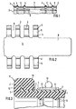
- Fig. 1 in schematischer Teildarstellung und im Axialschnitt ein Ausführungsbeispiel einer Hülse der Muffe;
- Fig. 2 in Draufsicht und in Teildarstellung das mit einer Zunge versehene Ende einer als offenes Band ausgebildeten Hülse der Muffe; und
- Fig. 3 im Axialschnitt und in Teildarstellung ein einsatzfertig vormontiertes Ausführungsbeispiel der Muffe.
- Figure 1 is a schematic partial representation and in axial section an embodiment of a sleeve of the sleeve.
- 2 shows a top view and a partial representation of the end of a sleeve of the sleeve which is designed as an open band and is provided with a tongue; and
- Fig. 3 in axial section and in partial representation a ready-to-use embodiment of the sleeve.
Das in der Fig. 1 gezeigte Ausführungsbeispiel einer Hülse 1 der Muffe der Erfindung ist eine zumindest im wesentlichen zylindrisch ausgebildete Hülse aus korrosionsbeständigem Stahlblech. Die Außenränder der Hülse sind unter Bildung von Radialstegen 2 zur Verankerung einer Manschette flanschartig nach radial außen umgebördelt. Nach axial einwärts schließt sich an den Radialsteg 2 jeweils ein glatt zylindrischer Abschnitt 3 des Mantels der Hülse 1 an, der der Aufnahme einer ringartigen Verstärkung der um den Radialsteg 2 herumgezogenen Manschette dient.The embodiment shown in Fig. 1 of a
Auf der dem Radialsteg 2 axial gegenüberliegenden Seite wird der zylindrische Hülsenabschnitt 3 durch eine von zwei ringförmigen Führungsrippen 4 begrenzt, die als radial auswärts vorspringende Sicken ausgebildet sind. Zwischen den beiden ringförmigen Führungsrippen 4,4 ist wiederum ein glatt zylindrischer Hülsenabschnitt 5 ausgebildet, dessen axiale Breite zumindest im wesentlichen der Breite eines zwischen die beiden Führungsrippen 4 einzulegenden Spannbandes entspricht.On the side axially opposite the
Die Hülse 1 weist weiterhin mit gleichem Winkelabstand voneinander über ihren gesamten Umfang verteilt, eine Reihe axialer Schlitze 6 auf, die sich vom Außenrand 7 der Hülse 1 nach axial einwärts bis hinter die zweite ringförmige Führungsrippe 4 erstrecken. Diese Axialschlitze 6 ermöglichen, daß die in den zylindrischen Abschnitten 5 um die Hülse 1 herumgelegten Spannbänder beim Anspannen eine Durchmesserverkleinerung der Hülse 1 bewirken können. Dies dient der Erzeugung eines radial einwärtsgerichteten Anpreßdruckes auf die innenliegende Gummimanschette zu Dichtzwecken.The
Im Gegensatz zu den in Fig. 1 gezeigten Ausführungsbeispiel einer Hülse der Muffe ist in der Fig. 2 in Draufsicht ein Ende einer als offenes Band ausgebildeten Hülse 1 gezeigt. Die Hülse 1 besteht wiederum aus korrosionsbeständigem Stahlblech. Die Schlitze 6 des in der Fig. 2 gezeigten Ausführungsbeispiels. der Hülse 1 sind wesentlich breiter als bei dem in Fig. 1 gezeigten Ausführungsbeispiel ausgelegt und weisen die gleiche Breite wie die zwischen zwei aufeinanderfolgenden Schlitze stehenbleibenden stegartigen oder fingerartigen Hülsenabschnitte auf, die im wesentlichen aus dem Radialsteg 2, dem ersten zylindrischen Abschnitt 3, den beiden Führungsrippen 4 und dem zwischen diesen beiden Führungsrippen ausgebildeten zylindrischen Abschnitt 5 gebildet werden.In contrast to the exemplary embodiment of a sleeve of the sleeve shown in FIG. 1, an end of a
An dem in der Fig. 2 rechts liegenden Ende des die Hülse 1 bildenden Bandes ist eine Zunge 8 ausgebildet, die sich, bezogen auf das die Hülse bildende Band, axial und, bezogen auf die zylindrische Hülse, in Umfangsrichtung so weit erstreckt, daß sie auch bei größtem zulässigem Umfang der Hülse für eine Stabilisierung ausreichend weit das gegenüberliegende Ende des Bandes überlappt, vorzugsweise insbesondere radial innerhalb, von außen gesehen also unterhalb des gegenüberliegenden Endes dieses überlappt. Dabei ist die Breite der Zunge 8 so bemessen, daß sie schmaler als der Abstand der beiden axial innersten Führungsrippen 4,4' voneinander ist. Dies gewährleistet, daß die Zunge in ihrer Verschiebbarkeit und Beweglichkeit in Umfangsrichtung nicht durch die angezogenen Spannbänder, die in den zylindrischen Abschnitten 5 liegen, beeinträchtigt wird. Eine solche Beweglichkeit fördert die Montagesicherheit und erleichtert den Montagevorgang.At the right in FIG. 2 the end of the band forming the
Ein Ausführungsbeispiel der vollständigen Muffe der Erfindung ist im Axialschnitt und in Teildarstellung in der Fig. 3 gezeigt. Die Hülse 1 besteht aus Kunststoff und weist an ihrem Außenrand einen flanschartig angeformten Radialsteg 2 auf. Die Manschette 9 umgreift mit ihrem Außenrand 10 den Außenrurad 7 und den Radialsteg 2 der Hülse 1, und zwar in der Weise, daß eine am Außenrand 10 der Manschette 9 angeformte ringartige Verstärkung 11 den Ringsteg 2 von axial innen her hintergreift. Der Ringsteg 2 ist zwischen dem Außenrand 10 und dem Ringabschnitt 11 der Manschette 9 axial eingespannt. Gegenüber dem zylindrischen Mantelabschnitt 3 der Hülse 1 weist der Ringabschnitt 11 der Manschette 9 außerdem eine radiale Vorspannung auf. Der Ringabschnitt 11 der Manschette 9 hat einen im wesentlichen quadratischen Quer schnitt mit stark abgerundeten Kanten. Der Ringabschnitt 11 ist so dimensioniert, daß es einer beachtlichen Kraft bedarf, um den Ringabschnitt 11 radial auszuweiten.An embodiment of the complete sleeve of the invention is shown in axial section and in partial representation in FIG. 3. The
Zwischen zwei radial auswärts vorspringen den angeformten ringförmigen Führungsrippen 4 ist ein Spannband 12 gegen axiale Verschiebung gesichert eingelegt, das durch schematisch angedeutete Spannmittel 13 im Sinne einer Radiusverkleinerung spannbar ist. Die durch diese Radiusverkleinerung erzeugte radial einwärts gerichtete Kraft wird direkt auf den zylindrischen Abschnitt 5 der Hülse 1 und von dieser Hülse 1 auf die Manschette 9 und auf an dieser ausgeformte Dichtungselemente 14 übertragen, die den Innenmantel der Manschette gegen den Außenmantel eines eingesteckten Rohrendes abdichten. Die Dichtungselemente 14 sind in dem hier gezeigten Ausführungsbeispiel als einfache Wulstringe dargestellt. Sie können in der Praxis selbstverständlich auch beliebige andere Form aufweisen, insbesondere auch lippenförmig ausgebildet sein.Between two protruding radially outward the integrally formed annular guide ribs 4, a
Claims (4)
Priority Applications (1)
| Application Number | Priority Date | Filing Date | Title |
|---|---|---|---|
| AT82100815T ATE8172T1 (en) | 1981-03-27 | 1982-02-04 | SLEEVE. |
Applications Claiming Priority (2)
| Application Number | Priority Date | Filing Date | Title |
|---|---|---|---|
| DE19813112258 DE3112258A1 (en) | 1981-03-27 | 1981-03-27 | SLEEVE |
| DE3112258 | 1981-03-27 |
Publications (2)
| Publication Number | Publication Date |
|---|---|
| EP0061569A1 EP0061569A1 (en) | 1982-10-06 |
| EP0061569B1 true EP0061569B1 (en) | 1984-06-27 |
Family
ID=6128529
Family Applications (1)
| Application Number | Title | Priority Date | Filing Date |
|---|---|---|---|
| EP82100815A Expired EP0061569B1 (en) | 1981-03-27 | 1982-02-04 | Socket end |
Country Status (4)
| Country | Link |
|---|---|
| US (1) | US4491350A (en) |
| EP (1) | EP0061569B1 (en) |
| AT (1) | ATE8172T1 (en) |
| DE (2) | DE3112258A1 (en) |
Families Citing this family (14)
| Publication number | Priority date | Publication date | Assignee | Title |
|---|---|---|---|---|
| JPH0516838Y2 (en) * | 1987-03-04 | 1993-05-06 | ||
| US4927189A (en) * | 1989-04-10 | 1990-05-22 | Burkit John W | Internal expansion coupling device |
| GB2253452B (en) * | 1991-03-05 | 1994-09-14 | Victaulic Plc | Pipe couplings |
| DE4207849C2 (en) * | 1992-03-12 | 1997-12-04 | Henrik Muecher | Pipe coupling for the tight connection of smooth ends of two pipes |
| FR2784166B1 (en) * | 1998-10-02 | 2000-11-17 | Renault | ARRANGEMENT FOR THE DEMOUNTABLE AND SEALED CONNECTION BETWEEN A TIP AND A DUCT OF A MOTOR VEHICLE AIR CIRCUIT |
| DE102005032341B3 (en) * | 2005-07-08 | 2007-02-15 | Mündener Gummiwerk Gmbh | Sleeve for attaching charge air hose to internal combustion engine nozzle, has circular part of external side coming into contact with internal side of nozzle such that internal pressure presses sleeve against nozzle |
| US20090051166A1 (en) * | 2007-05-17 | 2009-02-26 | Murray Corporation | Clamp-fitting stop |
| JP5075488B2 (en) * | 2007-06-06 | 2012-11-21 | 矢崎総業株式会社 | connector |
| DE102007061288B4 (en) * | 2007-12-19 | 2010-03-11 | Felber, Winfried | Device for connecting two lines |
| DE202011107927U1 (en) * | 2011-11-16 | 2013-02-20 | M.D.S. Meyer Gmbh | Connecting device for connecting two pipes |
| US9683691B2 (en) | 2013-05-20 | 2017-06-20 | Ford Global Technologies, Llc | Hose and system for hose clamp registration |
| JP6008249B2 (en) | 2013-07-04 | 2016-10-19 | 住友電装株式会社 | Grommet |
| GB201701347D0 (en) * | 2017-01-27 | 2017-03-15 | Flex-Seal Couplings Ltd | Improvements in or relating to pipe couplings |
| US20210285579A1 (en) * | 2020-03-13 | 2021-09-16 | Steere Enterprises, Inc. | Duct connector |
Citations (3)
| Publication number | Priority date | Publication date | Assignee | Title |
|---|---|---|---|---|
| DE7037139U (en) * | 1900-01-01 | Muecher H Muecher Ringe | ||
| DE1211045B (en) * | 1958-02-24 | 1966-02-17 | Scottish Agricultural Ind Ltd | Pipe coupling |
| DE2109566C (en) * | 1971-03-01 | 1973-07-12 |
Family Cites Families (10)
| Publication number | Priority date | Publication date | Assignee | Title |
|---|---|---|---|---|
| DE925743C (en) * | 1953-12-23 | 1955-03-28 | Ingbuero Hollender & Co | Insulating and heat-resistant pipe connection |
| US3334928A (en) * | 1965-03-10 | 1967-08-08 | John D Schmunk | Pipe coupling |
| DE1281759B (en) * | 1966-08-16 | 1969-04-30 | Jurid Werke Gmbh | Clamping sleeve for clamping sealing sleeves for connecting sleeveless, smooth pipes |
| US3430989A (en) * | 1967-12-20 | 1969-03-04 | Pacific Clay Products | Pipe coupling |
| US3682503A (en) * | 1970-09-11 | 1972-08-08 | Peerless Ind Inc | Pipe joint |
| DE2109566B2 (en) * | 1971-03-01 | 1972-12-21 | Hermann Mücher Mücher-Ringe, 5830 Schwelm | COUPLING COLLAR AND METHOD OF MANUFACTURING IT |
| US3796446A (en) * | 1971-12-10 | 1974-03-12 | Gen Connector Corp | Connector |
| ZA732442B (en) * | 1972-04-20 | 1975-01-29 | Wavin Bv | Pipe connection for plastic pipes comprising a transversly or helically corrugated pipe-connecting parat |
| US3840053A (en) * | 1973-02-05 | 1974-10-08 | Dresser Ind | Inside repair clamp for low pressure piping |
| US4380348A (en) * | 1981-02-18 | 1983-04-19 | Clamp-All Corp. | Pipe clamping assembly |
-
1981
- 1981-03-27 DE DE19813112258 patent/DE3112258A1/en not_active Withdrawn
-
1982
- 1982-02-04 EP EP82100815A patent/EP0061569B1/en not_active Expired
- 1982-02-04 AT AT82100815T patent/ATE8172T1/en not_active IP Right Cessation
- 1982-02-04 DE DE8282100815T patent/DE3260281D1/en not_active Expired
- 1982-03-10 US US06/356,690 patent/US4491350A/en not_active Expired - Fee Related
Patent Citations (3)
| Publication number | Priority date | Publication date | Assignee | Title |
|---|---|---|---|---|
| DE7037139U (en) * | 1900-01-01 | Muecher H Muecher Ringe | ||
| DE1211045B (en) * | 1958-02-24 | 1966-02-17 | Scottish Agricultural Ind Ltd | Pipe coupling |
| DE2109566C (en) * | 1971-03-01 | 1973-07-12 |
Also Published As
| Publication number | Publication date |
|---|---|
| ATE8172T1 (en) | 1984-07-15 |
| DE3260281D1 (en) | 1984-08-02 |
| US4491350A (en) | 1985-01-01 |
| DE3112258A1 (en) | 1982-10-07 |
| EP0061569A1 (en) | 1982-10-06 |
Similar Documents
| Publication | Publication Date | Title |
|---|---|---|
| EP0061569B1 (en) | Socket end | |
| EP0728979B1 (en) | Sealing connection between a plastic pipe and a connecting piece made of metal | |
| DE69900615T2 (en) | Device for connecting a pipe coupling | |
| DE3424675C2 (en) | Hose coupling | |
| DE3815173C2 (en) | ||
| DE2058203C2 (en) | Pipe connector | |
| EP2463565B1 (en) | Pipe connection assembly | |
| EP0205896A2 (en) | Pipe coupling | |
| CH664612A5 (en) | CONNECTOR TO CONNECT THE END OF TWO TUBES. | |
| CH647586A5 (en) | TUBE CLAMP. | |
| DE202016104723U1 (en) | Gasket for insertion into a piping system | |
| DE2517808B2 (en) | PIPE COUPLING | |
| DE3247452C1 (en) | Pipe connection | |
| DE19542463B4 (en) | pipe coupling | |
| DE60212270T2 (en) | Coupling sleeve with compressed in the axial direction sealing ring | |
| DE1650200C3 (en) | Sealing arrangement for the sealing bridging of the ends of pipes equipped with or without end collars | |
| DE2221674A1 (en) | Hose coupling | |
| DE19615861A1 (en) | Constant velocity joint sealing bellows | |
| EP0611855B1 (en) | Device for connecting two internal ceramic pipe sections of a chimney | |
| DE2758592A1 (en) | JOINT FORMATION FOR FASTENING A PIPE IN THE OPENING OF A WALL | |
| DE2440886C3 (en) | Pipe connection for pressure pipelines | |
| DE69212784T2 (en) | Exhaust pipe segment with double push-in socket | |
| DE4241622A1 (en) | Coupling for tightly joining socket free ends of two pipes - has elastomeric collar with or without outer sleeve, and at least two clamping elements | |
| DE4103702C1 (en) | ||
| DE20219600U1 (en) | Press connection arrangement and holding element for a press connection |
Legal Events
| Date | Code | Title | Description |
|---|---|---|---|
| PUAI | Public reference made under article 153(3) epc to a published international application that has entered the european phase |
Free format text: ORIGINAL CODE: 0009012 |
|
| AK | Designated contracting states |
Designated state(s): AT BE CH DE FR GB IT NL SE |
|
| 17P | Request for examination filed |
Effective date: 19821007 |
|
| ITF | It: translation for a ep patent filed | ||
| GRAA | (expected) grant |
Free format text: ORIGINAL CODE: 0009210 |
|
| AK | Designated contracting states |
Designated state(s): AT BE CH DE FR GB IT LI NL SE |
|
| REF | Corresponds to: |
Ref document number: 8172 Country of ref document: AT Date of ref document: 19840715 Kind code of ref document: T |
|
| REF | Corresponds to: |
Ref document number: 3260281 Country of ref document: DE Date of ref document: 19840802 |
|
| ET | Fr: translation filed | ||
| PLBE | No opposition filed within time limit |
Free format text: ORIGINAL CODE: 0009261 |
|
| STAA | Information on the status of an ep patent application or granted ep patent |
Free format text: STATUS: NO OPPOSITION FILED WITHIN TIME LIMIT |
|
| 26N | No opposition filed | ||
| ITTA | It: last paid annual fee | ||
| PGFP | Annual fee paid to national office [announced via postgrant information from national office to epo] |
Ref country code: AT Payment date: 19930125 Year of fee payment: 12 |
|
| PGFP | Annual fee paid to national office [announced via postgrant information from national office to epo] |
Ref country code: SE Payment date: 19930218 Year of fee payment: 12 |
|
| PG25 | Lapsed in a contracting state [announced via postgrant information from national office to epo] |
Ref country code: AT Effective date: 19940204 |
|
| PG25 | Lapsed in a contracting state [announced via postgrant information from national office to epo] |
Ref country code: SE Effective date: 19940205 |
|
| EUG | Se: european patent has lapsed |
Ref document number: 82100815.8 Effective date: 19940910 |
|
| PGFP | Annual fee paid to national office [announced via postgrant information from national office to epo] |
Ref country code: GB Payment date: 19960111 Year of fee payment: 15 |
|
| PGFP | Annual fee paid to national office [announced via postgrant information from national office to epo] |
Ref country code: FR Payment date: 19960129 Year of fee payment: 15 |
|
| PGFP | Annual fee paid to national office [announced via postgrant information from national office to epo] |
Ref country code: CH Payment date: 19960201 Year of fee payment: 15 |
|
| PG25 | Lapsed in a contracting state [announced via postgrant information from national office to epo] |
Ref country code: GB Effective date: 19970204 |
|
| PGFP | Annual fee paid to national office [announced via postgrant information from national office to epo] |
Ref country code: BE Payment date: 19970214 Year of fee payment: 16 |
|
| PGFP | Annual fee paid to national office [announced via postgrant information from national office to epo] |
Ref country code: NL Payment date: 19970220 Year of fee payment: 16 |
|
| PG25 | Lapsed in a contracting state [announced via postgrant information from national office to epo] |
Ref country code: LI Effective date: 19970228 Ref country code: CH Effective date: 19970228 |
|
| PGFP | Annual fee paid to national office [announced via postgrant information from national office to epo] |
Ref country code: DE Payment date: 19970401 Year of fee payment: 16 |
|
| GBPC | Gb: european patent ceased through non-payment of renewal fee |
Effective date: 19970204 |
|
| REG | Reference to a national code |
Ref country code: CH Ref legal event code: PL |
|
| PG25 | Lapsed in a contracting state [announced via postgrant information from national office to epo] |
Ref country code: FR Effective date: 19971030 |
|
| REG | Reference to a national code |
Ref country code: FR Ref legal event code: ST |
|
| PG25 | Lapsed in a contracting state [announced via postgrant information from national office to epo] |
Ref country code: BE Free format text: LAPSE BECAUSE OF NON-PAYMENT OF DUE FEES Effective date: 19980228 |
|
| BERE | Be: lapsed |
Owner name: WOCO FRANZ-JOSEF WOLF & CO. Effective date: 19980228 |
|
| PG25 | Lapsed in a contracting state [announced via postgrant information from national office to epo] |
Ref country code: NL Free format text: LAPSE BECAUSE OF NON-PAYMENT OF DUE FEES Effective date: 19980901 |
|
| NLV4 | Nl: lapsed or anulled due to non-payment of the annual fee |
Effective date: 19980901 |
|
| PG25 | Lapsed in a contracting state [announced via postgrant information from national office to epo] |
Ref country code: DE Free format text: LAPSE BECAUSE OF NON-PAYMENT OF DUE FEES Effective date: 19981103 |