EP0061335A1 - Pneumatic granular or seed applicator - Google Patents
Pneumatic granular or seed applicator Download PDFInfo
- Publication number
- EP0061335A1 EP0061335A1 EP82301464A EP82301464A EP0061335A1 EP 0061335 A1 EP0061335 A1 EP 0061335A1 EP 82301464 A EP82301464 A EP 82301464A EP 82301464 A EP82301464 A EP 82301464A EP 0061335 A1 EP0061335 A1 EP 0061335A1
- Authority
- EP
- European Patent Office
- Prior art keywords
- casing
- auger
- substance
- discharge
- distribution
- Prior art date
- Legal status (The legal status is an assumption and is not a legal conclusion. Google has not performed a legal analysis and makes no representation as to the accuracy of the status listed.)
- Granted
Links
- 239000000463 material Substances 0.000 claims abstract description 36
- 239000003337 fertilizer Substances 0.000 claims abstract description 5
- 239000004009 herbicide Substances 0.000 claims abstract description 5
- 239000008187 granular material Substances 0.000 claims description 31
- 239000000126 substance Substances 0.000 claims description 31
- 241000239290 Araneae Species 0.000 claims description 7
- 230000005484 gravity Effects 0.000 claims description 2
- 230000003028 elevating effect Effects 0.000 claims 12
- 238000000034 method Methods 0.000 claims 6
- 238000006073 displacement reaction Methods 0.000 claims 2
- 239000000203 mixture Substances 0.000 description 4
- 230000000712 assembly Effects 0.000 description 3
- 238000000429 assembly Methods 0.000 description 3
- 238000010276 construction Methods 0.000 description 2
- 238000011065 in-situ storage Methods 0.000 description 2
- 239000002245 particle Substances 0.000 description 2
- 238000000605 extraction Methods 0.000 description 1
- 238000004519 manufacturing process Methods 0.000 description 1
- 239000002184 metal Substances 0.000 description 1
- 238000011144 upstream manufacturing Methods 0.000 description 1
Images

Classifications
-
- A—HUMAN NECESSITIES
- A01—AGRICULTURE; FORESTRY; ANIMAL HUSBANDRY; HUNTING; TRAPPING; FISHING
- A01C—PLANTING; SOWING; FERTILISING
- A01C7/00—Sowing
- A01C7/08—Broadcast seeders; Seeders depositing seeds in rows
- A01C7/081—Seeders depositing seeds in rows using pneumatic means
- A01C7/084—Pneumatic distribution heads for seeders
-
- A—HUMAN NECESSITIES
- A01—AGRICULTURE; FORESTRY; ANIMAL HUSBANDRY; HUNTING; TRAPPING; FISHING
- A01C—PLANTING; SOWING; FERTILISING
- A01C15/00—Fertiliser distributors
- A01C15/04—Fertiliser distributors using blowers
Definitions
- This invention relates to new and useful improvements in pneumatic granular applicators, particularly applicators in which granulated material such as fertilizer, herbicides or small seeds is fed into an air stream which then distributes same to the individual ground engaging applicators on the implement.
- granulated material such as fertilizer, herbicides and the like is distributed by feeding same to one or more horizontally rotating spinners situated below or adjacent to the hopper.
- the efficiency, accuracy and evenness of distribution of such devices is effected by prevailing winds, sloping ground conditions, density of the material and more importantly by the size of the particles, particularly when the particle size varies considerably in a single batch of material as is often the case.
- the present invention overcomes these disadvantages by providing a vertically situated auger, the speed of which is controllable within limits, said auger being operatively connected to the hopper and moving the granular material or seed upwardly to an enclosed rotary fan-like distributor whereupon it may be evenly distributed into the conveying air stream and discharged through the main distribution conduits to the individual applicators.
- a pneumatic applicator for granular materials such as granular fertilizer, herbicides or the like and seeds. It comprises a substantially vertically situated auger assembly which includes an upper discharge end.
- the auger assembly is operatively connected to a source of power and also to a source of granular material, seed or the like.
- Means are provided on the upper end of the auger assembly for moving said material towards the outer wall of the distribution casing and a plurality of discharge conduits for conveying the material from the casing through said discharge conduits.
- a further advantage of the present invention is to provide a device of the character herewithin described which maintains considerable accuracy of distribution and which is readily adapted for use with various forms of granular material and/or seeds merely by varying the speed of the vertically situated feed auger and the intake of the material from the hopper.
- Another advantage of the present invention is to provide a device of the character herewithin described which is simple in construction, economical in manufacture and otherwise well suited to the purpose for which it is designed.
- reference character 10 illustrates a vertically situated auger tube operatively connected to a hopper 38 which may contain the granular material or seed, as the case may be.
- An auger shaft 11 is rotatable therein with an auger flight 12 formed or secured therearound and the shaft is connected to a source of power such as a variable speed orbital motor 39 operated by pump 40 which in turn is connected to a source of power 41.
- a source of power such as a variable speed orbital motor 39 operated by pump 40 which in turn is connected to a source of power 41.
- This permits rotation of the auger shaft and flight with the speed or rotation being controllable by conventional .neans such as valve 42 (see Figure 11).
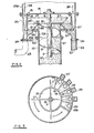
- An annular casing 13 extends upwardly from adjacent the upper end of the auger, terminating in a horizontal plate 14 secured thereto by means of nut and bolt assemblies 15 or the like, and the upper end 16 of the auger shaft is bearingly supported for rotation within this plate.
- a plurality of radially extending distributor blades or vanes 17 are secured to the upper end of the auger shaft and below the plate 14 and rotate with the auger and within casing 13 so that the grain or granular material passing upwardly through the auger tube 10, is picked up and distributed radially by the blades 17 in an even manner, outwardly against the vertical sides of the casing 13.
- a cone shaped annular collar 18 extends outwardly and downwardly from the upper end 19 of the auger tube portion 10A and in conjunction with the vertical wall 20 of the casing 13, forms a discharge area for the granular material or seeds moved outwardly by the distributor blades 17, annular base plate 19A extending from the outer lower end of the collar 18 to the lower end of the casing wall 20.
- the upper end portion 10A of the auger tube, the annular collar 18 and the base plate 18A be formed as a separate unit, being detachably secured to the upper end of the auger tube 10 by means of flanged collars 10B and 10C secured together by nut and bolt assemblies 10D or the equivalent.
- a plurality of discharge collars 21 are provided through the base plate 18A around the base 22 of the annular channel defined by the wall 20 and the collar 18 and each of these terminates in a downwardly extending discharge conduit 22 to which a flexible conduit portion 23 is secured as by clamps 24 or the like.
- a plurality of air conduits 25 operatively connected to a source of air via manifold 25A, developed by a fan 43 driven by an orbital motor 44 also connected to the source of power 41 (see Figure 11), said air travelling in the direction of arrows 26.
- manifold 25A developed by a fan 43 driven by an orbital motor 44 also connected to the source of power 41 (see Figure 11), said air travelling in the direction of arrows 26.
- the individual air conduits 25 may be formed integrally with the corresponding discharge conduits 22 and be secured in place around the wall 20 by any conventional means such as sheet metal screws 18B.
- a venturi 27 is formed within the air conduits 25 adjacent the junction thereof with the material discharge collars 21 thus speeding up the air flow and lowering the pressure to assist in the extraction of the granular material or seeds from the annular channel surrounding the upper end of the auger tube.
- the distributor blades 17 rotate at the same rate as the auger shaft and flight and distribute the material evenly to the outside of the casing 13 whereupon it is deposited through the collars 21 and picked up in the air stream to pass downwardly through the distributor conduits 23, carried by the air stream to conventional individual applicators (not illustrated).
- This embodiment includes the upwardly extending auger casing 10, an auger shaft 11 and the auger flight 12 moving the material upwardly through the tube 10 in a manner similar to that hereinbefore described.
- a spider assembly 28 spans the upper end of a casing 29 and supports the upper end 30 of the auger shaft 11 within a bearing assembly 31 which is secured to the spider assembly.
- Distributor blades 32 are secured to the upper end of the shaft below the spider assembly 28, acting in a manner similar to the distributor blades 17 of the previous embodiment, with the exception that an inverted dish-shaped shroud 33 is secured to the upper edges of the distributor blades 32 and rotates therewith. This assists in directing the material augered upwardly by the auger assembly towards the outside of the casing 29 and directs it downwardly into the annular channel 34 defined by the annular cone shaped collar 18 and the lower annular wall portion 29A, whereupon it passes through discharge collars 35 into flexible distribution conduits 23 secured by clamps 24.
- the lines 37 indicate direction of flow of the granular material and/or seeds.
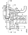
- Figure 6 shows the preferred embodiment which includes not only a different positioning for the venturi but also, and alternatively, an additional air and chemical mixture feed assembly.
- an air-manifold collectively designated 45 is bolted to the upper end flange 46 of the distributor casing 29 by means of nut and bolt assemblies 47 and includes the annular plenum 48 operatively connected to the fan assembly 43 by means of one or more connecting conduits 49 detachably secured to collars 50 extending from and communicating with the plenum 48.
- the flange 46 extends inwardly as an annular flange portion 46A and supports a plurality of downwardly extending venturi tubes 51 there being one such venturi tube situated vertically above each discharge collar 35 situated within the base of the distributor casing. Each venturi tube terminates spaced above the discharge collar substantially level with the lower periphery 52 of the rotating shroud 33 which is clearly shown in Figure 6.
- the venturi 51 speeds up the air stream travelling downwardly from the plenum 48 in the direction of arrows 53 to pick up the granular material from the distributor blades 32 and the shroud 33 ' and discharges same through the discharge collars 35 into the distributor conduit 23.
- a reverse Venturi 54 is situated within each discharge collar 35 to decelerate the air and granular material passing therethrough whereupon it flows through the distributor conduits 33 to the individual distributors 55 supported on the booms 56 extending from frame 57, said structure being basically conventional. Details are shown in Figure 8 and include ground engaging wheels 58 upon which the supporting structure 57 is mounted together with hopper 38.
- An additional air and chemical granular mixture may be supplied in conjunction with the granular mixture supplied by the auger assembly 10, 11 and 12. If this is desired, it may be supplied through an upper conduit 59, from a separate hopper and entrained within air from a fan (not illustrated) similar to fan 43.
- the conduit 59 terminates in a down-turned end portion 59A which freely engages within a vertically situated collar 60.
- This collar which has a closed face 61, is secured to the upper end 30 of the auger shaft 11 and rotates therewith. It is situated centrally off the annular manifold 48 and a plurality of pipes or conduits 62 are secured to and communicate with adjacent to the face of the collar 60 and extend horizontally outwardly therefrom towards the vertical wall casing 29.
- This material moving assembly is situated above the spider 28 and above the distributor blades 32 and shroud 33 and, as it rotates, it distributes granular material in train with air, into the casing 29 where it falls by gravity to mix with the material being fed to the casing 29 by means of the auger assembly. It is then picked up by the air stream and injected through the discharge collars 35 and mixed with the material from the auger assembly.
- FIG. 9 An alternative embodiment is shown in Figure 9 which includes the vertical situated auger assembly 10, 11 and 12 moving granular material upwardly to be distributed outwardly within the distributor casing 13 by means of the blades 32'and shroud 33.
- This embodiment the upper end 16 of the auger shaft is supported within a bearing 64 situated within the upper horizontal closure panel 14 secured to the upper end of the distributor casing 13.
- Each distributor conduit 23 is connected at the distal or lower end thereof, to a collar 65 extending from and communicating with the interior of a horizontal feed conduit 66 operatively connected by the upstream end thereof to a fan assembly similar to fan 43 and by the downstream thereof to a granular material distributor assembly 55, it being under- stoodstood that each individual discharge conduit 23 is provided with its own feed conduit 66.
- the collar 65 leads into the conduit 66 with the axis inclined from the vertical so that it leads in downstream and a venturi section 67 is provided within the conduit 66 adjacent to the connection of the collar 65 with the conduit 66 in order to speed up the air flow at this point thereby creating an area of low pressure within the discharge conduit 23 which facilitates the feeding in of a granular material distributed outwardly by the blades 32.
- the auger shaft 11 is preferably driven hydraulically and includes variable speed means as hereinbefore described.
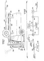
- the hopper 38 includes a discharge conveyor 68 shown schematically in Figure 1 mounted upon the frame 57 supported by the ground engaging wheels 58.
- a hitch 69 may connect the device to a source of power such as a tractor or the like (not illustrated).
- An adjustable discharge gate 70 is shown schematically in Figure 1 and controls the ejection of the granular material 71 together with the speed of the feed conveyor 68 which is driven from one of the ground engaging wheels 58 so that the speed is controlled by the speed of the assembly across the ground.
Landscapes
- Life Sciences & Earth Sciences (AREA)
- Soil Sciences (AREA)
- Environmental Sciences (AREA)
- Sowing (AREA)
- Fertilizing (AREA)
Abstract
Description
- This invention relates to new and useful improvements in pneumatic granular applicators, particularly applicators in which granulated material such as fertilizer, herbicides or small seeds is fed into an air stream which then distributes same to the individual ground engaging applicators on the implement.
- Conventionally, granulated material such as fertilizer, herbicides and the like is distributed by feeding same to one or more horizontally rotating spinners situated below or adjacent to the hopper. The efficiency, accuracy and evenness of distribution of such devices is effected by prevailing winds, sloping ground conditions, density of the material and more importantly by the size of the particles, particularly when the particle size varies considerably in a single batch of material as is often the case.
- The present invention overcomes these disadvantages by providing a vertically situated auger, the speed of which is controllable within limits, said auger being operatively connected to the hopper and moving the granular material or seed upwardly to an enclosed rotary fan-like distributor whereupon it may be evenly distributed into the conveying air stream and discharged through the main distribution conduits to the individual applicators.
- In accordance with the invention there is provided a pneumatic applicator for granular materials such as granular fertilizer, herbicides or the like and seeds. It comprises a substantially vertically situated auger assembly which includes an upper discharge end. The auger assembly is operatively connected to a source of power and also to a source of granular material, seed or the like. It includes a distribution casing surrounding the discharge end with the auger assembly for receiving material conveyed by the auger assembly. Means are provided on the upper end of the auger assembly for moving said material towards the outer wall of the distribution casing and a plurality of discharge conduits for conveying the material from the casing through said discharge conduits.
- A further advantage of the present invention is to provide a device of the character herewithin described which maintains considerable accuracy of distribution and which is readily adapted for use with various forms of granular material and/or seeds merely by varying the speed of the vertically situated feed auger and the intake of the material from the hopper.
- Another advantage of the present invention is to provide a device of the character herewithin described which is simple in construction, economical in manufacture and otherwise well suited to the purpose for which it is designed.
-
- Figure 1 is a schematic side elevation of the device.
- Figure 2 is a fragmentary partially schematic cross sectional view of the upper end of the auger showing the distribution device of one embodiment of the device.
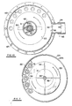
- Figure 3 is a top plan view of Figure 1.
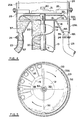
- Figure 4 is a view similar to Figure 1, but showing an alternative construction.
- Figure 5 is a top plan view of Figure 4.
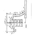
- Figure 6 is a vertical section of the preferred embodiment of th^ device.
- Figure 7 is a horizontal section substantially along the line 7-7 of Figure 6.
- Figure 8 is a partial schematic rear view, sectioned in part showing the embodiment of Figure 6 in situ.
- Figure 9 is a fragmentary vertical section of a further embodiment.
- Figure 10 is a horizontal section substantially along the line 10-10 of Figure 6.
- Figure 11 is a schematic view of the system.
- In the drawings like characters of reference indicate corresponding parts in the different figures.
- Proceeding therefore to describe the invention in detail,
reference character 10 illustrates a vertically situated auger tube operatively connected to ahopper 38 which may contain the granular material or seed, as the case may be. - An auger shaft 11 is rotatable therein with an
auger flight 12 formed or secured therearound and the shaft is connected to a source of power such as a variable speedorbital motor 39 operated bypump 40 which in turn is connected to a source ofpower 41. This permits rotation of the auger shaft and flight with the speed or rotation being controllable by conventional .neans such as valve 42 (see Figure 11). - An
annular casing 13 extends upwardly from adjacent the upper end of the auger, terminating in ahorizontal plate 14 secured thereto by means of nut andbolt assemblies 15 or the like, and theupper end 16 of the auger shaft is bearingly supported for rotation within this plate. A plurality of radially extending distributor blades orvanes 17 are secured to the upper end of the auger shaft and below theplate 14 and rotate with the auger and withincasing 13 so that the grain or granular material passing upwardly through theauger tube 10, is picked up and distributed radially by theblades 17 in an even manner, outwardly against the vertical sides of thecasing 13. - A cone shaped
annular collar 18 extends outwardly and downwardly from theupper end 19 of the auger tube portion 10A and in conjunction with thevertical wall 20 of thecasing 13, forms a discharge area for the granular material or seeds moved outwardly by thedistributor blades 17, annular base plate 19A extending from the outer lower end of thecollar 18 to the lower end of thecasing wall 20. - It is preferable that the upper end portion 10A of the auger tube, the
annular collar 18 and thebase plate 18A be formed as a separate unit, being detachably secured to the upper end of theauger tube 10 by means of flanged collars 10B and 10C secured together by nut and bolt assemblies 10D or the equivalent. - A plurality of
discharge collars 21 are provided through thebase plate 18A around thebase 22 of the annular channel defined by thewall 20 and thecollar 18 and each of these terminates in a downwardly extendingdischarge conduit 22 to which aflexible conduit portion 23 is secured as byclamps 24 or the like. - Situated around the outer surface of the
vertical wall 20 of thecasing 13 is a plurality ofair conduits 25 operatively connected to a source of air viamanifold 25A, developed by afan 43 driven by an orbital motor 44 also connected to the source of power 41 (see Figure 11), said air travelling in the direction ofarrows 26. There is onesuch air conduit 25 for eachdischarge conduit 22 and theseair conduits 25 each blend into thecorresponding discharge conduit 22 in a downwardly extending direction as clearly shown in Figure 2. Theindividual air conduits 25 may be formed integrally with thecorresponding discharge conduits 22 and be secured in place around thewall 20 by any conventional means such assheet metal screws 18B. Aventuri 27 is formed within theair conduits 25 adjacent the junction thereof with thematerial discharge collars 21 thus speeding up the air flow and lowering the pressure to assist in the extraction of the granular material or seeds from the annular channel surrounding the upper end of the auger tube. Thedistributor blades 17 rotate at the same rate as the auger shaft and flight and distribute the material evenly to the outside of thecasing 13 whereupon it is deposited through thecollars 21 and picked up in the air stream to pass downwardly through thedistributor conduits 23, carried by the air stream to conventional individual applicators (not illustrated). - In the embodiment shown in Figures 4 and 5, much of the structure is similar to that shown in Figures 1 and 2 so that similar reference characters have been used where applicable. This embodiment includes the upwardly extending
auger casing 10, an auger shaft 11 and theauger flight 12 moving the material upwardly through thetube 10 in a manner similar to that hereinbefore described. - A
spider assembly 28 spans the upper end of acasing 29 and supports theupper end 30 of the auger shaft 11 within abearing assembly 31 which is secured to the spider assembly.Distributor blades 32 are secured to the upper end of the shaft below thespider assembly 28, acting in a manner similar to thedistributor blades 17 of the previous embodiment, with the exception that an inverted dish-shaped shroud 33 is secured to the upper edges of thedistributor blades 32 and rotates therewith. This assists in directing the material augered upwardly by the auger assembly towards the outside of thecasing 29 and directs it downwardly into theannular channel 34 defined by the annular coneshaped collar 18 and the lowerannular wall portion 29A, whereupon it passes throughdischarge collars 35 intoflexible distribution conduits 23 secured byclamps 24. - Air enters the upper end of casing 29 (similar to casing 13) from the
fan 43 travelling in the direction ofarrows 26 and passes between theouter periphery 33A of the dish-shaped shroud 33 and thewall 29 of the casing, downwardly into theannular channel 34 and thence out through theindividual discharge collars 35 with the curved invertedperiphery 33A of the dish and thevertical wall 29 acting to define aventuri 36 to assist in the picking up and even distribution of the granular material or seeds being distributed radially by thefan blades 32. In both embodiments, thelines 37 indicate direction of flow of the granular material and/or seeds. - Figure 6 shows the preferred embodiment which includes not only a different positioning for the venturi but also, and alternatively, an additional air and chemical mixture feed assembly.
- Where common parts exist relative to the previous embodiment, similar reference characters have been used. It utilizes the auger assembly including the
auger tube 10, shaft 11 andauger 12 together with the dish-shaped shroud 33 and thedistributing blades 32 situated at theupper end 19 of the auger assembly. Theupper end 30 of the auger shaft 11 is supported withinbearing 31 which in turn is supported centrally at thespider assembly 28 extending from thedistributor casing 29. - In this embodiment, an air-manifold collectively designated 45 is bolted to the
upper end flange 46 of thedistributor casing 29 by means of nut andbolt assemblies 47 and includes theannular plenum 48 operatively connected to thefan assembly 43 by means of one or more connectingconduits 49 detachably secured tocollars 50 extending from and communicating with theplenum 48. - The
flange 46 extends inwardly as anannular flange portion 46A and supports a plurality of downwardly extendingventuri tubes 51 there being one such venturi tube situated vertically above eachdischarge collar 35 situated within the base of the distributor casing. Each venturi tube terminates spaced above the discharge collar substantially level with thelower periphery 52 of the rotatingshroud 33 which is clearly shown in Figure 6. - The
venturi 51 speeds up the air stream travelling downwardly from theplenum 48 in the direction ofarrows 53 to pick up the granular material from thedistributor blades 32 and theshroud 33'and discharges same through thedischarge collars 35 into thedistributor conduit 23. It will be observed that a reverse Venturi 54 is situated within eachdischarge collar 35 to decelerate the air and granular material passing therethrough whereupon it flows through thedistributor conduits 33 to theindividual distributors 55 supported on thebooms 56 extending fromframe 57, said structure being basically conventional. Details are shown in Figure 8 and include groundengaging wheels 58 upon which the supportingstructure 57 is mounted together withhopper 38. - An additional air and chemical granular mixture may be supplied in conjunction with the granular mixture supplied by the
auger assembly upper conduit 59, from a separate hopper and entrained within air from a fan (not illustrated) similar tofan 43. Theconduit 59 terminates in a down-turnedend portion 59A which freely engages within a verticallysituated collar 60. This collar, which has a closed face 61, is secured to theupper end 30 of the auger shaft 11 and rotates therewith. It is situated centrally off theannular manifold 48 and a plurality of pipes orconduits 62 are secured to and communicate with adjacent to the face of thecollar 60 and extend horizontally outwardly therefrom towards thevertical wall casing 29. This material moving assembly is situated above thespider 28 and above thedistributor blades 32 andshroud 33 and, as it rotates, it distributes granular material in train with air, into thecasing 29 where it falls by gravity to mix with the material being fed to thecasing 29 by means of the auger assembly. It is then picked up by the air stream and injected through thedischarge collars 35 and mixed with the material from the auger assembly. - This permits two types of material to be introduced to the assembly, in varying proportions, and to be mixed together and distributed upon the ground surface.
- This combined structure is shown, in situ, in Figure 8 which illustrares schematically a rear view of the device.
- An alternative embodiment is shown in Figure 9 which includes the vertical situated
auger assembly distributor casing 13 by means of theblades 32'and shroud 33. This embodiment, theupper end 16 of the auger shaft is supported within abearing 64 situated within the upperhorizontal closure panel 14 secured to the upper end of thedistributor casing 13. - Each
distributor conduit 23 is connected at the distal or lower end thereof, to acollar 65 extending from and communicating with the interior of ahorizontal feed conduit 66 operatively connected by the upstream end thereof to a fan assembly similar tofan 43 and by the downstream thereof to a granularmaterial distributor assembly 55, it being under- stoodstood that eachindividual discharge conduit 23 is provided with itsown feed conduit 66. - The
collar 65 leads into theconduit 66 with the axis inclined from the vertical so that it leads in downstream and aventuri section 67 is provided within theconduit 66 adjacent to the connection of thecollar 65 with theconduit 66 in order to speed up the air flow at this point thereby creating an area of low pressure within thedischarge conduit 23 which facilitates the feeding in of a granular material distributed outwardly by theblades 32. - In all embodiments, the auger shaft 11 is preferably driven hydraulically and includes variable speed means as hereinbefore described.
- It is preferable that the
hopper 38 includes adischarge conveyor 68 shown schematically in Figure 1 mounted upon theframe 57 supported by theground engaging wheels 58. A hitch 69 may connect the device to a source of power such as a tractor or the like (not illustrated). - An
adjustable discharge gate 70 is shown schematically in Figure 1 and controls the ejection of thegranular material 71 together with the speed of thefeed conveyor 68 which is driven from one of theground engaging wheels 58 so that the speed is controlled by the speed of the assembly across the ground.
Claims (23)
Applications Claiming Priority (2)
| Application Number | Priority Date | Filing Date | Title |
|---|---|---|---|
| GB8109305 | 1981-03-25 | ||
| GB8109305 | 1981-03-25 |
Publications (2)
| Publication Number | Publication Date |
|---|---|
| EP0061335A1 true EP0061335A1 (en) | 1982-09-29 |
| EP0061335B1 EP0061335B1 (en) | 1986-01-15 |
Family
ID=10520638
Family Applications (1)
| Application Number | Title | Priority Date | Filing Date |
|---|---|---|---|
| EP82301464A Expired EP0061335B1 (en) | 1981-03-25 | 1982-03-22 | Pneumatic granular or seed applicator |
Country Status (5)
| Country | Link |
|---|---|
| US (1) | US4475819A (en) |
| EP (1) | EP0061335B1 (en) |
| AU (1) | AU546910B2 (en) |
| CA (1) | CA1192935A (en) |
| DE (1) | DE3268483D1 (en) |
Cited By (10)
| Publication number | Priority date | Publication date | Assignee | Title |
|---|---|---|---|---|
| EP0102333A1 (en) * | 1982-07-27 | 1984-03-07 | Ingenjörsfirman Alf Andersson Handelsbolag | Method and apparatus for spreading and distributing a solid or liquid particulate material |
| EP0251401A1 (en) * | 1986-06-23 | 1988-01-07 | Multinorm B.V. | Device for distributing a granular or powdery substance |
| EP0309608A3 (en) * | 1987-10-02 | 1989-07-26 | Rabewerk Heinrich Clausing | A distribution head for a pneumatic drill |
| FR2648732A1 (en) * | 1989-05-30 | 1990-12-28 | Ag Chem Equipment Co | PRESSURIZED PNEUMATIC SYSTEM FOR THE SUBSTANTIALLY UNIFORM DISTRIBUTION OF SOLID PARTICLES IN PARTICLES ON THE GROUND |
| FR2676328A1 (en) * | 1991-05-17 | 1992-11-20 | Ballu Jean Louis | Device for cultivation of vines, making it possible to carry out the operations of powdering, manuring and treatment |
| EP2208410A1 (en) * | 2009-01-19 | 2010-07-21 | Amazonen-Werke H. Dreyer GmbH & Co. KG | Distributor head |
| EP2878187A1 (en) * | 2013-11-26 | 2015-06-03 | Heinrich Spitz | Device for the targeted application of goods, in particular goods to be spread, in particular seed |
| IT201800003966A1 (en) * | 2018-03-26 | 2019-09-26 | Matermacc S P A | Improved distributor device for agricultural machinery |
| EP4074158A1 (en) * | 2021-04-14 | 2022-10-19 | Amazonen-Werke H. Dreyer SE & Co. KG | Distributing device for a pneumatic agricultural distributor |
| CN119866728A (en) * | 2025-03-18 | 2025-04-25 | 河南农业大学 | Full-automatic seeder of agricultural breeding dish |
Families Citing this family (25)
| Publication number | Priority date | Publication date | Assignee | Title |
|---|---|---|---|---|
| US5028009A (en) * | 1989-12-22 | 1991-07-02 | Ag-Chem Equipment Co., Inc. | Distributor head for use with booms having shut-off capability |
| US5052627A (en) * | 1990-05-23 | 1991-10-01 | Charles Balmer | Spreading of particulate material |
| FR2677900B1 (en) * | 1991-06-24 | 1993-10-08 | Sames Sa | INSTALLATION FOR ELECTROSTATIC SPRAYING OF POWDER COATING PRODUCT. |
| US5725332A (en) * | 1995-09-14 | 1998-03-10 | Saf-T-Source, Inc. | Air lock feeder apparatus |
| US5725160A (en) * | 1995-09-14 | 1998-03-10 | Saf-T-Source, Inc. | Chip blower apparatus |
| US5794847A (en) * | 1996-10-25 | 1998-08-18 | Stocker; Russell | Air assisted insect dispensing apparatus and delivery process |
| US6078635A (en) * | 1998-02-05 | 2000-06-20 | Dubois; Jerry | Seed or particle-counting device |
| US6571736B2 (en) | 2001-02-22 | 2003-06-03 | Lance H. Patterson | Feeder for moist fish feed |
| US7264423B2 (en) * | 2005-02-02 | 2007-09-04 | Cnh Canada, Ltd. | Hose restraint apparatus |
| US8104648B2 (en) * | 2007-10-22 | 2012-01-31 | The Fountainhead Group, Inc. | Mixing applicator |
| US8272501B1 (en) * | 2009-04-16 | 2012-09-25 | Curcuri Thomas J | Pneumatic powder feeder system for municipal sewer lift station |
| DE202009007971U1 (en) * | 2009-06-08 | 2010-10-28 | Claudius Peters Technologies Gmbh | Device for moistening a bulk material |
| CZ308919B6 (en) | 2012-11-28 | 2021-09-01 | Biocont Laboratory | Method, device and mixture for aerial application of parasitoids of the genus Trichogramma for plant protection and method for evaluation of aerial application of parasitoids of the genus Trichogramma |
| US9296571B2 (en) * | 2013-02-18 | 2016-03-29 | Charles Truan | Cab-forward truck bed mounted material spreader |
| US20150231654A1 (en) * | 2014-02-19 | 2015-08-20 | Pursell Manufacturing Corp. | Material spraying machine |
| CN109068580A (en) | 2016-04-04 | 2018-12-21 | 清洁种子农业技术有限公司 | System and method for controlling the flowing of the agricultural product from variable ratio mixing application device |
| US20210161124A1 (en) * | 2018-06-06 | 2021-06-03 | Pioneer Hi-Bred International, Inc. | Method and device for distributing beneficial arthropods |
| US11343958B2 (en) * | 2018-08-27 | 2022-05-31 | Lynx Ag, LLC | High flow fertilizer/air meter with secondary nozzling |
| US11606897B2 (en) * | 2020-04-03 | 2023-03-21 | Harvest International, Inc. | Bulk seed distributor |
| WO2024009244A1 (en) * | 2022-07-06 | 2024-01-11 | Loam Bio Pty Ltd. | Systems and methods for agricultural additive delivery |
| NL2033135B1 (en) * | 2022-09-26 | 2024-04-03 | Brinkman Agro B V | Arthropod distributor with an inner reservoir and external housing delimiting a transportation space with an Archimedes screw therein. |
| USD1072001S1 (en) | 2023-02-15 | 2025-04-22 | Harvest International, Inc. | Circular bulk seed distributor |
| WO2025054429A1 (en) * | 2023-09-07 | 2025-03-13 | Smith Fox Llc | Supply system for agricultural equipment |
| USD1106280S1 (en) | 2024-01-11 | 2025-12-16 | Harvest International, Inc. | Circular seed manifold |
| US20250228154A1 (en) | 2024-01-11 | 2025-07-17 | Harvest International, Inc. | Circular bulk seed distributor manifold |
Citations (4)
| Publication number | Priority date | Publication date | Assignee | Title |
|---|---|---|---|---|
| DE284449C (en) * | ||||
| GB191228060A (en) * | 1912-12-05 | 1913-08-14 | Matthew Herrod | Apparatus for Distributing Powder on Crops. |
| FR1564295A (en) * | 1967-05-03 | 1969-04-18 | ||
| FR1569181A (en) * | 1967-05-31 | 1969-05-30 |
Family Cites Families (15)
| Publication number | Priority date | Publication date | Assignee | Title |
|---|---|---|---|---|
| US2601534A (en) * | 1952-06-24 | Distributor | ||
| US2521888A (en) * | 1948-03-26 | 1950-09-12 | John O Wilson | Mine duster |
| GB683531A (en) * | 1949-06-27 | 1952-12-03 | Theodor Bottlander | An improved distributor for top-dressing land |
| US2923574A (en) * | 1956-09-13 | 1960-02-02 | Fuss Eric William | Distributing means with spinner for grain |
| US2976643A (en) * | 1958-05-20 | 1961-03-28 | J W Chafer Ltd | Machine for spraying powdered materials |
| GB873718A (en) * | 1959-03-18 | 1961-07-26 | Lundell Great Britain Ltd | Improvements in agricultural machines |
| US3169799A (en) * | 1963-01-11 | 1965-02-16 | Hoyle B Puckett | Auger feed injector for pneumatic conveyer |
| US3258296A (en) * | 1964-03-20 | 1966-06-28 | Funk Irwin Von | Pneumatic material conveyor |
| DE1657591B1 (en) * | 1966-01-22 | 1970-07-16 | Heinrich Weiste | Device for sowing grain and / or spreading grainy fertilizer |
| BE736074A (en) * | 1968-08-14 | 1969-12-16 | ||
| NO123975B (en) * | 1969-09-01 | 1972-02-14 | Globus Maskinfab As | |
| US3643872A (en) * | 1969-10-20 | 1972-02-22 | Lely Corp The | Device for spreading granular or powdery material |
| US3926377A (en) * | 1975-01-02 | 1975-12-16 | Arvid B Johnson | Apparatus for spreading granulated and pulverized material |
| US4024822A (en) * | 1975-12-22 | 1977-05-24 | Arthur Ross | Pneumatic seeder assembly |
| AT353044B (en) * | 1977-10-21 | 1979-10-25 | Weiste Heinrich | PNEUMATICALLY OPERATED MACHINE FOR DISTRIBUTING GRAINY GOODS |
-
1981
- 1981-07-31 US US06/288,675 patent/US4475819A/en not_active Expired - Fee Related
-
1982
- 1982-03-16 CA CA000398400A patent/CA1192935A/en not_active Expired
- 1982-03-19 AU AU81736/82A patent/AU546910B2/en not_active Ceased
- 1982-03-22 EP EP82301464A patent/EP0061335B1/en not_active Expired
- 1982-03-22 DE DE8282301464T patent/DE3268483D1/en not_active Expired
Patent Citations (4)
| Publication number | Priority date | Publication date | Assignee | Title |
|---|---|---|---|---|
| DE284449C (en) * | ||||
| GB191228060A (en) * | 1912-12-05 | 1913-08-14 | Matthew Herrod | Apparatus for Distributing Powder on Crops. |
| FR1564295A (en) * | 1967-05-03 | 1969-04-18 | ||
| FR1569181A (en) * | 1967-05-31 | 1969-05-30 |
Cited By (12)
| Publication number | Priority date | Publication date | Assignee | Title |
|---|---|---|---|---|
| EP0102333A1 (en) * | 1982-07-27 | 1984-03-07 | Ingenjörsfirman Alf Andersson Handelsbolag | Method and apparatus for spreading and distributing a solid or liquid particulate material |
| EP0251401A1 (en) * | 1986-06-23 | 1988-01-07 | Multinorm B.V. | Device for distributing a granular or powdery substance |
| US4874130A (en) * | 1986-06-23 | 1989-10-17 | Multinorm B.V. | Device for distributing a granular or powdery substance |
| EP0309608A3 (en) * | 1987-10-02 | 1989-07-26 | Rabewerk Heinrich Clausing | A distribution head for a pneumatic drill |
| FR2648732A1 (en) * | 1989-05-30 | 1990-12-28 | Ag Chem Equipment Co | PRESSURIZED PNEUMATIC SYSTEM FOR THE SUBSTANTIALLY UNIFORM DISTRIBUTION OF SOLID PARTICLES IN PARTICLES ON THE GROUND |
| FR2676328A1 (en) * | 1991-05-17 | 1992-11-20 | Ballu Jean Louis | Device for cultivation of vines, making it possible to carry out the operations of powdering, manuring and treatment |
| EP2208410A1 (en) * | 2009-01-19 | 2010-07-21 | Amazonen-Werke H. Dreyer GmbH & Co. KG | Distributor head |
| EP2878187A1 (en) * | 2013-11-26 | 2015-06-03 | Heinrich Spitz | Device for the targeted application of goods, in particular goods to be spread, in particular seed |
| IT201800003966A1 (en) * | 2018-03-26 | 2019-09-26 | Matermacc S P A | Improved distributor device for agricultural machinery |
| EP3545740A1 (en) * | 2018-03-26 | 2019-10-02 | Matermacc S.p.A. | Seed distribution head for agricultural machinery |
| EP4074158A1 (en) * | 2021-04-14 | 2022-10-19 | Amazonen-Werke H. Dreyer SE & Co. KG | Distributing device for a pneumatic agricultural distributor |
| CN119866728A (en) * | 2025-03-18 | 2025-04-25 | 河南农业大学 | Full-automatic seeder of agricultural breeding dish |
Also Published As
| Publication number | Publication date |
|---|---|
| AU546910B2 (en) | 1985-09-26 |
| AU8173682A (en) | 1982-09-30 |
| DE3268483D1 (en) | 1986-02-27 |
| CA1192935A (en) | 1985-09-03 |
| US4475819A (en) | 1984-10-09 |
| EP0061335B1 (en) | 1986-01-15 |
Similar Documents
| Publication | Publication Date | Title |
|---|---|---|
| EP0061335A1 (en) | Pneumatic granular or seed applicator | |
| US5915312A (en) | Pneumatic seed delivery system | |
| US4026437A (en) | Seed drill | |
| US4024822A (en) | Pneumatic seeder assembly | |
| US7270064B2 (en) | Apparatus for discrete distribution of granules | |
| JP3178680B2 (en) | Powder supply hopper | |
| US3515315A (en) | Combined seed and fertilizer drills for agricultural use | |
| US3926377A (en) | Apparatus for spreading granulated and pulverized material | |
| US4215824A (en) | Pneumatically-operated machine for spreading granular material | |
| EP0934689A3 (en) | Improved conveyor tube and distribution header for air conveyor | |
| US4480794A (en) | Air seeder distributor | |
| US20220061243A1 (en) | Device and method for pollen application | |
| AU723527B2 (en) | Application of coatings to seeds, etc. | |
| US4128191A (en) | Collector for a pneumatic dispenser | |
| US2545829A (en) | Duster | |
| US4177940A (en) | Flock fiber feeding apparatus having a plurality of impellers and a venturi flow tube | |
| JPH0729037B2 (en) | Method and apparatus for coating particulate material with powdered material | |
| US6357971B1 (en) | Mobile blower system for depositing grass seed and organic material | |
| US4573800A (en) | Blender bulk feed valve | |
| GB2302075A (en) | Pneumatic conveyor system | |
| CN219593408U (en) | Water feeder | |
| US2619767A (en) | Crop dusting unit | |
| CN218786616U (en) | Continuous fermentation disc system | |
| CN117461430A (en) | Horizontal cylinder granule seed stirring cladding machine | |
| JPH02207726A (en) | Feeding of fish farming tank |
Legal Events
| Date | Code | Title | Description |
|---|---|---|---|
| PUAI | Public reference made under article 153(3) epc to a published international application that has entered the european phase |
Free format text: ORIGINAL CODE: 0009012 |
|
| AK | Designated contracting states |
Designated state(s): BE DE FR GB IT NL SE |
|
| 17P | Request for examination filed |
Effective date: 19830302 |
|
| GRAA | (expected) grant |
Free format text: ORIGINAL CODE: 0009210 |
|
| AK | Designated contracting states |
Designated state(s): BE DE FR GB IT NL SE |
|
| PG25 | Lapsed in a contracting state [announced via postgrant information from national office to epo] |
Ref country code: NL Effective date: 19860115 Ref country code: IT Free format text: LAPSE BECAUSE OF FAILURE TO SUBMIT A TRANSLATION OF THE DESCRIPTION OR TO PAY THE FEE WITHIN THE PRESCRIBED TIME-LIMIT;WARNING: LAPSES OF ITALIAN PATENTS WITH EFFECTIVE DATE BEFORE 2007 MAY HAVE OCCURRED AT ANY TIME BEFORE 2007. THE CORRECT EFFECTIVE DATE MAY BE DIFFERENT FROM THE ONE RECORDED. Effective date: 19860115 Ref country code: FR Free format text: THE PATENT HAS BEEN ANNULLED BY A DECISION OF A NATIONAL AUTHORITY Effective date: 19860115 Ref country code: BE Effective date: 19860115 |
|
| PG25 | Lapsed in a contracting state [announced via postgrant information from national office to epo] |
Ref country code: SE Effective date: 19860131 |
|
| REF | Corresponds to: |
Ref document number: 3268483 Country of ref document: DE Date of ref document: 19860227 |
|
| EN | Fr: translation not filed | ||
| NLV1 | Nl: lapsed or annulled due to failure to fulfill the requirements of art. 29p and 29m of the patents act | ||
| PLBE | No opposition filed within time limit |
Free format text: ORIGINAL CODE: 0009261 |
|
| STAA | Information on the status of an ep patent application or granted ep patent |
Free format text: STATUS: NO OPPOSITION FILED WITHIN TIME LIMIT |
|
| GBPC | Gb: european patent ceased through non-payment of renewal fee | ||
| PG25 | Lapsed in a contracting state [announced via postgrant information from national office to epo] |
Ref country code: DE Effective date: 19861202 |
|
| 26N | No opposition filed | ||
| PG25 | Lapsed in a contracting state [announced via postgrant information from national office to epo] |
Ref country code: GB Effective date: 19881121 |