EP0061276B1 - Driveline for regenerative braking - Google Patents
Driveline for regenerative braking Download PDFInfo
- Publication number
- EP0061276B1 EP0061276B1 EP82301298A EP82301298A EP0061276B1 EP 0061276 B1 EP0061276 B1 EP 0061276B1 EP 82301298 A EP82301298 A EP 82301298A EP 82301298 A EP82301298 A EP 82301298A EP 0061276 B1 EP0061276 B1 EP 0061276B1
- Authority
- EP
- European Patent Office
- Prior art keywords
- flywheel
- transmission
- engine
- speed
- clutch
- Prior art date
- Legal status (The legal status is an assumption and is not a legal conclusion. Google has not performed a legal analysis and makes no representation as to the accuracy of the status listed.)
- Expired
Links
Images
Classifications
-
- B—PERFORMING OPERATIONS; TRANSPORTING
- B60—VEHICLES IN GENERAL
- B60T—VEHICLE BRAKE CONTROL SYSTEMS OR PARTS THEREOF; BRAKE CONTROL SYSTEMS OR PARTS THEREOF, IN GENERAL; ARRANGEMENT OF BRAKING ELEMENTS ON VEHICLES IN GENERAL; PORTABLE DEVICES FOR PREVENTING UNWANTED MOVEMENT OF VEHICLES; VEHICLE MODIFICATIONS TO FACILITATE COOLING OF BRAKES
- B60T1/00—Arrangements of braking elements, i.e. of those parts where braking effect occurs specially for vehicles
- B60T1/02—Arrangements of braking elements, i.e. of those parts where braking effect occurs specially for vehicles acting by retarding wheels
- B60T1/10—Arrangements of braking elements, i.e. of those parts where braking effect occurs specially for vehicles acting by retarding wheels by utilising wheel movement for accumulating energy, e.g. driving air compressors
-
- B—PERFORMING OPERATIONS; TRANSPORTING
- B60—VEHICLES IN GENERAL
- B60K—ARRANGEMENT OR MOUNTING OF PROPULSION UNITS OR OF TRANSMISSIONS IN VEHICLES; ARRANGEMENT OR MOUNTING OF PLURAL DIVERSE PRIME-MOVERS IN VEHICLES; AUXILIARY DRIVES FOR VEHICLES; INSTRUMENTATION OR DASHBOARDS FOR VEHICLES; ARRANGEMENTS IN CONNECTION WITH COOLING, AIR INTAKE, GAS EXHAUST OR FUEL SUPPLY OF PROPULSION UNITS IN VEHICLES
- B60K6/00—Arrangement or mounting of plural diverse prime-movers for mutual or common propulsion, e.g. hybrid propulsion systems comprising electric motors and internal combustion engines ; Control systems therefor, i.e. systems controlling two or more prime movers, or controlling one of these prime movers and any of the transmission, drive or drive units Informative references: mechanical gearings with secondary electric drive F16H3/72; arrangements for handling mechanical energy structurally associated with the dynamo-electric machine H02K7/00; machines comprising structurally interrelated motor and generator parts H02K51/00; dynamo-electric machines not otherwise provided for in H02K see H02K99/00
- B60K6/08—Prime-movers comprising combustion engines and mechanical or fluid energy storing means
- B60K6/10—Prime-movers comprising combustion engines and mechanical or fluid energy storing means by means of a chargeable mechanical accumulator, e.g. flywheel
- B60K6/105—Prime-movers comprising combustion engines and mechanical or fluid energy storing means by means of a chargeable mechanical accumulator, e.g. flywheel the accumulator being a flywheel
-
- F—MECHANICAL ENGINEERING; LIGHTING; HEATING; WEAPONS; BLASTING
- F16—ENGINEERING ELEMENTS AND UNITS; GENERAL MEASURES FOR PRODUCING AND MAINTAINING EFFECTIVE FUNCTIONING OF MACHINES OR INSTALLATIONS; THERMAL INSULATION IN GENERAL
- F16H—GEARING
- F16H33/00—Gearings based on repeated accumulation and delivery of energy
- F16H33/02—Rotary transmissions with mechanical accumulators, e.g. weights, springs, intermittently-connected flywheels
-
- F—MECHANICAL ENGINEERING; LIGHTING; HEATING; WEAPONS; BLASTING
- F02—COMBUSTION ENGINES; HOT-GAS OR COMBUSTION-PRODUCT ENGINE PLANTS
- F02B—INTERNAL-COMBUSTION PISTON ENGINES; COMBUSTION ENGINES IN GENERAL
- F02B3/00—Engines characterised by air compression and subsequent fuel addition
- F02B3/06—Engines characterised by air compression and subsequent fuel addition with compression ignition
-
- Y—GENERAL TAGGING OF NEW TECHNOLOGICAL DEVELOPMENTS; GENERAL TAGGING OF CROSS-SECTIONAL TECHNOLOGIES SPANNING OVER SEVERAL SECTIONS OF THE IPC; TECHNICAL SUBJECTS COVERED BY FORMER USPC CROSS-REFERENCE ART COLLECTIONS [XRACs] AND DIGESTS
- Y02—TECHNOLOGIES OR APPLICATIONS FOR MITIGATION OR ADAPTATION AGAINST CLIMATE CHANGE
- Y02T—CLIMATE CHANGE MITIGATION TECHNOLOGIES RELATED TO TRANSPORTATION
- Y02T10/00—Road transport of goods or passengers
- Y02T10/60—Other road transportation technologies with climate change mitigation effect
- Y02T10/62—Hybrid vehicles
Landscapes
- Engineering & Computer Science (AREA)
- Mechanical Engineering (AREA)
- Chemical & Material Sciences (AREA)
- Combustion & Propulsion (AREA)
- Transportation (AREA)
- General Engineering & Computer Science (AREA)
- Arrangement Of Transmissions (AREA)
- Arrangement Or Mounting Of Propulsion Units For Vehicles (AREA)
- One-Way And Automatic Clutches, And Combinations Of Different Clutches (AREA)
- Friction Gearing (AREA)
Description
- This invention relates to drivelines for regenerative braking, especially to those drivelines including continuously-variable-ratio transmissions.
- A hybrid driveline for regenerative braking of a vehicle, using a change-speed gearbox with one input taken via a fluid coupling from a flywheel and another input taken. via a lockable fluid coupling from an engine, is known from U.S. Patent 2935899, corresponding to the preamble of claim
- 1. Both these inputs are taken at nominally equal speeds, and moreover the two connections are entirely independent. This means that when the input from the flywheel is connected via its fluid coupling, and when it is faster than the locked drive from the engine, both the flywheel and the engine are driving the transmission. The two fluid couplings need to be controlled and this requires a fairly complex, separate control system. It is an object of the present invention to simplify the control of the engine and flywheel.
- The advantageous use of a continuously variable ratio transmission to control regenerative braking with a flywheel is recognized in, for example, U.S. Patent No. 4131171. However, there the flywheel is in the driveline between the engine and the transmission, and the problem of simplifying the engine and flywheel control remains.
- According to the present invention there is provided a driveline which includes a variable ratio transmission, an engine for driving the transmission, and a flywheel for driving the transmission which is itself driven by the transmission to brake the vehicle, wherein the flywheel is coupled to the transmission via a releasable clutch and wherein the engine is coupled to the transmission via a first over-running clutch which is arranged to decouple when the speed on the transmission side exceeds that on the engine side, the invention being characterized in that the transmission is a continuously-variable ratio transmission, in that the releasable clutch is a second over-running clutch which is arranged to decouple when its speed on the flywheel side exceeds that on the transmission side, and in that a speed controlled clutch is provided in parallel with the second over-running clutch in order to lock the flywheel into the driveline when the flywheel is accelerated to a value above that corresponding to maximum engine speed.
- The fact that the transmission is driven either by the engine or by the flywheel, but not by both together, makes controlling the engine and flywheel simpler. Advantageously, the flywheel can only drive the transmission at speeds in excess of those at which the engine can drive the transmission.
- Advantageously, the flywheel is connected to the transmission downstream of the first over-running clutch in the drive direction.
- The engine is coupled and decoupled automatically with this arrangement. The engine is automatically decoupled when the flywheel speed is in the range where it can drive the transmission and automatically recoupled when the flywheel can no longer provide drive.
- The flywheel thus couples in automatically for energisation but only becomes locked in for de- energisation at a certain speed. Preferably, the speed controlled clutch is a centrifugal clutch.
- The engine could be spark ignition but is preferably compression ignition, and the continuously variable-ratio transmission could be of the pulley and belt type but is preferably of the toroidal race rolling friction type, where traction takes place through an elastohydrodynamic film.
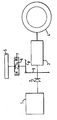
- A driveline constructed in accordance with the invention will now be described, by way of example, with reference to the accompanying drawing, which is a schematic view of the driveline.
- Referring to the drawing, the driveline has a diesel engine 1 as prime mover which is coupled to a continuously-variable-ratio transmission 3 via a sprag over-running clutch 2. The continuously-variable-ratio transmission 3 drives a drive axle 4.
- A flywheel 5 is provided for the purpose of regenerative braking. The flywheel is coupled to the input of the continuously-variable-ratio transmission downstream of the sprag clutch 2, and via a second sprag clutch 6 which is combined with a centrifugal clutch 7 and
drive gears 8 and 9. - The sprag clutches 2 and 6 are arranged so that they over-run, respectively, when the speed of the transmission side 3 exceeds that on the engine side 1 and when the speed on the flywheel side 5 exceeds that on the
drive gears 8, 9 side. The centrifugal clutch closes when the flywheel speed is greater than the speed the flywheel would have (allowing for the step-up of the gears 8,9) if driven by the engine at its full speed. - The operation of the drive-train is as follows. When starting the engine of the vehicle with the flywheel 5 stationary, the flywheel 5 will be clutched into the engine from the start because of the sprag clutches 2 and 6. The engine is accelerated to its maximum speed, which will then be the minimum operational speed of the flywheel.
- During subsequent driving ofthevehicle,thefly- wheel 5 is decoupled provided the engine speed is less than its maximum value, and the vehicle can be driven in the same way as if the flywheel was not present. (The centrifugal clutch 7 is decoupled since it only engages at a speed above maximum engine speed). If the flywheel speed drops to below the engine maximum speed, it is accelerated again and becomes decoupled when the engine speed reduces.
- Regenerative braking takes place by accelerating the flywheel 5, achieved by downshifting the transmission 3, and the energy of the vehicle is fed via the drive axle 4 along the transmission 3 from the output and to the input end. The input accelerates above the maximum engine speed, causing the engine sprag to freewheel, and the flywheel sprag 6 to couple. Regenerative braking now takes place.
- When the flywheel accelerates to a particular value above that corresponding to maximum engine speed, the centrifugal clutch 7 closes.
- The flywheel 5 is now locked into the driveline until it slows down to the value at which the centrifugal clutch opens. Since this value is above that corresponding to maximum engine speed, it follows that the engine is decoupled from the driveline during this time. The stored energy is now available for vehicle drive through the transmission 3.
- As the flywheel 5 approaches the speed at which the centrifugal clutch 7 opens, the clutch will slip and the slow down of the input of the transmission 3 will increase. The engine must now be accelerated from idle to its required running speed, and the sprag clutch 2 will couple when the speed on the engine side equals that on the transmission input side. The engine is now available for normal drive. The drag torque produced by the slipping centrifugal clutch is used to bridge the.switch from flywheel to engine power, and will disappear as it further slows the flywheel.
- As an example of suitable speeds of operation the diesel engine may have a maximum speed of approximately 3000 rpm and the centrifugal clutch 7, which governs the speeds at which the flywheel can drive the transmission may close at a value such that the speed of
drivegear 9 is within the range 3250 rpm to 3500 rpm. The maximum flywheel speed may be such that the speed ofdrivegear 9 is approximately 6000 rpm. - The minimum flywheel speed wil be the maximum speed of the engine. If during long periods of engine only running the flywheel drops below this referred speed (referred speed being the speed at the drivegear 9) i.e. 3000 rpm, the engine accelerates to bring it back to 3000 rpm, this could be accomplished by means of a sensor on the flywheel.
- However, if the engine was running at a low speed e.g. 1000 rpm, one could then face the problem that the engine would be continually speeding up to bring the flywheel to the referred speed of 3000 rpm and then dropping back, only to speed up again shortly when the flywheel dropped below 3000 rpm again. For this reason, the engine could be allowed an overspeed range, that is, it could speed up to 3250 rpm (with the centrifugal clutch operation now at 3500 rpm) to bring the flywheel to within its operational range, while still having a maximum speed of 3000 rpm . if driving the engine only. This will of course ensure that the flywheel will be 'transparent' for all but very short periods.
- With the above arrangement, the vehicle will be driven either by the flywheel or by the engine, and switching between the two is automatic.
- If it is desired that the flywheel is not clutched in on start-up, for example, to prevent heavy loading on the starter motor, a disconnect clutch could be incorporated.
- The engine alone could be started on the starter motor, and the flywheel could be engaged with the engine idling. A dryplate clutch could be used as the disconnect clutch. As an alternative, the flywheel could be accelerated from rest before the engine is started by using an electric motor (which could be the starter motor). When the flywheel is running slightly faster than the value corresponding to engine idle speed, the engine is free to start without engaging the sprag clutches.
- If desired, a release mechanism could be incorporated in the combined flywheel clutch in order to disconnect the fully energised flywheel. This would improve driveline efficiency with the vehicle stationary.
- If desired, the centrifugal clutch could be dispensed with and any clutch (such as a multiplate electrically controlled clutch) could replace it, the clutch being arranged in parallel with the over-running clutch 6 to lock it up over the desired speed range.
- Also, the flywheel could be arranged to drive the steering pump, compressors for a brake pump, air compressor for power operated doors, or other ancilliaries normally driven by the engine.
- The transmission is preferably a toroidal race rolling friction type. Such transmissions are described for example in paper number 80-C2/ DET-59 of the American Society of Mechanical Engineers as well as in United Kingdom Patent Application Number 2023753 and European Patent Publication Number 0006690. Reduction gears may be required at its input to restrict the maximum speed at the input.
- The driveline of the invention is suited to use in heavy goods vehicles, where the braking energies are appreciable, and especially to use in public service vehicles (that is, buses) where a lot of stopping and starting is involved.
Claims (5)
Applications Claiming Priority (2)
| Application Number | Priority Date | Filing Date | Title |
|---|---|---|---|
| GB8108920 | 1981-03-21 | ||
| GB8108920A GB2095188A (en) | 1981-03-21 | 1981-03-21 | Driveline for regenerative braking |
Publications (2)
| Publication Number | Publication Date |
|---|---|
| EP0061276A1 EP0061276A1 (en) | 1982-09-29 |
| EP0061276B1 true EP0061276B1 (en) | 1987-04-29 |
Family
ID=10520563
Family Applications (1)
| Application Number | Title | Priority Date | Filing Date |
|---|---|---|---|
| EP82301298A Expired EP0061276B1 (en) | 1981-03-21 | 1982-03-15 | Driveline for regenerative braking |
Country Status (6)
| Country | Link |
|---|---|
| US (1) | US4519485A (en) |
| EP (1) | EP0061276B1 (en) |
| JP (1) | JPS57201723A (en) |
| DE (1) | DE3276159D1 (en) |
| DK (1) | DK125482A (en) |
| GB (1) | GB2095188A (en) |
Families Citing this family (23)
| Publication number | Priority date | Publication date | Assignee | Title |
|---|---|---|---|---|
| DE3224981C2 (en) * | 1982-07-03 | 1986-09-11 | Daimler-Benz Ag, 7000 Stuttgart | Drive unit for motor vehicles, in particular omnibuses, with a hydrodynamic flow unit and a continuously variable gear change gear |
| DE3224982C2 (en) * | 1982-07-03 | 1986-09-11 | Daimler-Benz Ag, 7000 Stuttgart | Drive arrangement for motor vehicles with a drive machine and a flywheel as energy storage |
| DE3308477A1 (en) * | 1983-03-10 | 1984-09-13 | Ernst Lehmann | Vehicle with brake system and drive system |
| GB2136369A (en) * | 1983-03-15 | 1984-09-19 | Leyland Vehicles | Vehicle driveline for regenerative braking |
| FR2548289B1 (en) * | 1983-06-28 | 1985-12-13 | Renault | HYDROSTATIC TRANSMISSION WITH INTEGRATED BRAKE ENERGY RECOVERY |
| JPS62196438A (en) * | 1986-02-22 | 1987-08-29 | Hiromichi Namikoshi | Torque converter employing mechanical switching operation |
| FR2837531B1 (en) * | 2002-03-19 | 2005-12-02 | Peugeot Citroen Automobiles Sa | MECHANICAL SYSTEM FOR HIGH PRESSURE PUMP |
| NZ533349A (en) * | 2004-06-04 | 2007-01-26 | Muthuvetpillai Jegatheeson | Drive and regenerative braking system using first and second transmission units and flywheel |
| US7654238B2 (en) * | 2004-11-08 | 2010-02-02 | Ford Global Technologies, Llc | Systems and methods for controlled shutdown and direct start for internal combustion engine |
| US7207916B2 (en) * | 2005-01-05 | 2007-04-24 | Deere & Company | Transmission for power take-off |
| GB2440996A (en) | 2006-05-25 | 2008-02-20 | Powertrain Technology Ltd | Power transmission system |
| EP2055519A1 (en) * | 2007-11-02 | 2009-05-06 | Gomecsys B.V. | A vehicle and a method of controlling the vehicle |
| GB2460237A (en) * | 2008-05-20 | 2009-11-25 | Torotrak Dev Ltd | Vehicle kinetic energy recovery system |
| WO2010104258A1 (en) * | 2009-03-11 | 2010-09-16 | Park Min Chul | Mechanical energy storage and recycling apparatus |
| US20100304920A1 (en) * | 2009-05-28 | 2010-12-02 | Bernard Joseph Simon | Hybrid Assembly , A Hybrid Power-Train , And A Method For Operating A Selectively Movable Assembly |
| US8142329B2 (en) * | 2009-09-18 | 2012-03-27 | Ford Global Technologies, Llc | Controlling torque in a flywheel powertrain |
| US20110079106A1 (en) * | 2009-10-07 | 2011-04-07 | Liu Shih Chen | Power generating system and apparatus |
| JP4947124B2 (en) * | 2009-11-05 | 2012-06-06 | 株式会社デンソー | In-vehicle power transmission system |
| KR101856079B1 (en) * | 2009-11-19 | 2018-05-09 | 디티아이 그룹 비.브이. | Flywheel module comprising a centrifugal disengaging clutch |
| RU2457380C2 (en) * | 2011-01-21 | 2012-07-27 | Игорь Владимирович Леонов | Control method for braking energy regeneration mechanism and device for its implementation |
| CN102166953A (en) * | 2011-04-14 | 2011-08-31 | 孙奇 | Inertia wheel drive vehicle |
| JP2015205526A (en) * | 2014-04-17 | 2015-11-19 | トヨタ自動車株式会社 | hybrid vehicle |
| HU230864B1 (en) * | 2016-09-23 | 2018-11-29 | László Bacskó | Flywheel drive |
Family Cites Families (15)
| Publication number | Priority date | Publication date | Assignee | Title |
|---|---|---|---|---|
| US2935899A (en) * | 1953-09-24 | 1960-05-10 | Daimler Benz Ag | Driving device for vehicles |
| US3641843A (en) * | 1969-09-22 | 1972-02-15 | Joseph Lemmens | Variable-speed transmission |
| JPS4710208U (en) * | 1971-03-01 | 1972-10-06 | ||
| US3749194A (en) * | 1971-03-19 | 1973-07-31 | J Bardwick | Intertial energy system for vehicles |
| DE2153961A1 (en) * | 1971-10-29 | 1973-05-03 | Volkswagenwerk Ag | HYBRID DRIVE |
| JPS494324U (en) * | 1972-04-12 | 1974-01-15 | ||
| US3882950A (en) * | 1972-07-11 | 1975-05-13 | James Neil Strohlein | Vehicle power system for limited vehicle movement without use of fuel |
| US4041801A (en) * | 1976-01-21 | 1977-08-16 | Anderson Warren A | Mechanism of improving the regulation of rotary power sources subject to intermittent short term overload |
| IL49201A (en) * | 1976-03-12 | 1980-02-29 | Scientific Res Foundation | Vehicle drive system including a flywheel and selectable coupling means |
| DE2641886A1 (en) * | 1976-09-17 | 1978-03-30 | Maschf Augsburg Nuernberg Ag | HYBRID DRIVE MOTOR VEHICLE |
| US4131171A (en) * | 1977-04-11 | 1978-12-26 | Keyes John H | Low energy consumption vehicle propelled by thermal engine |
| US4276951A (en) * | 1977-05-13 | 1981-07-07 | Colt Industries Operating Corp | Vehicular energy storing means and system |
| JPS5444345U (en) * | 1977-08-29 | 1979-03-27 | ||
| US4393964A (en) * | 1979-03-23 | 1983-07-19 | Ipanema Company | Hybrid power system and method for operating same |
| DE3022373A1 (en) * | 1980-06-14 | 1981-12-24 | Volkswagenwerk Ag | VEHICLE, PARTICULARLY PERSONAL VEHICLES |
-
1981
- 1981-03-21 GB GB8108920A patent/GB2095188A/en not_active Withdrawn
-
1982
- 1982-03-15 EP EP82301298A patent/EP0061276B1/en not_active Expired
- 1982-03-15 DE DE8282301298T patent/DE3276159D1/en not_active Expired
- 1982-03-18 US US06/359,505 patent/US4519485A/en not_active Expired - Lifetime
- 1982-03-19 DK DK125482A patent/DK125482A/en not_active Application Discontinuation
- 1982-03-23 JP JP57046157A patent/JPS57201723A/en active Granted
Also Published As
| Publication number | Publication date |
|---|---|
| DK125482A (en) | 1982-09-22 |
| JPS57201723A (en) | 1982-12-10 |
| DE3276159D1 (en) | 1987-06-04 |
| US4519485A (en) | 1985-05-28 |
| JPS641334B2 (en) | 1989-01-11 |
| EP0061276A1 (en) | 1982-09-29 |
| GB2095188A (en) | 1982-09-29 |
Similar Documents
| Publication | Publication Date | Title |
|---|---|---|
| EP0061276B1 (en) | Driveline for regenerative braking | |
| US4679646A (en) | Driveline for regenerative braking | |
| US4499965A (en) | Hybrid drive arrangement | |
| US6852063B2 (en) | Automotive internal combustion engine control system | |
| US6364807B1 (en) | Control strategy for a hybrid powertrain for an automotive vehicle | |
| US5258651A (en) | Electrically biased starting reaction device for a power transmission | |
| US6334498B1 (en) | Hybrid vehicle | |
| US6962550B2 (en) | Control for vehicle including electric motor powered by engine driven generator | |
| US6808470B2 (en) | Motor vehicle drive | |
| EP0645271B1 (en) | Power train and power transmission therefor | |
| US4495836A (en) | Automotive vehicle power drive system | |
| JP3584680B2 (en) | Hybrid vehicle drive system of internal combustion engine and electric motor | |
| JP2002362197A (en) | Power train | |
| JPH07266932A (en) | Automatic starting and stopping device of engine | |
| US6969338B2 (en) | Method for controlling and regulating a drive train | |
| US5186291A (en) | Transmission for a vehicle | |
| JPH10339185A (en) | Combined veicle driving apparatus of internal combustion engine and electric motor and control method thereof | |
| JPH106806A (en) | Vehicle | |
| CN109311472B (en) | Method for operating a continuously variable transmission in a motor vehicle equipped with a continuously variable transmission | |
| JP2631882B2 (en) | Control device for automatic clutch for vehicles | |
| US2916932A (en) | Power transmission | |
| US20230070632A1 (en) | Selectable torque path torque converter architecture | |
| JP2872369B2 (en) | Diesel vehicle idling prevention control method | |
| GB2585819A (en) | Vehicle drive lines | |
| GB2582811A (en) | Vehicle drive lines |
Legal Events
| Date | Code | Title | Description |
|---|---|---|---|
| PUAI | Public reference made under article 153(3) epc to a published international application that has entered the european phase |
Free format text: ORIGINAL CODE: 0009012 |
|
| AK | Designated contracting states |
Designated state(s): BE DE FR GB IT NL SE |
|
| 17P | Request for examination filed |
Effective date: 19830117 |
|
| GRAA | (expected) grant |
Free format text: ORIGINAL CODE: 0009210 |
|
| ITF | It: translation for a ep patent filed |
Owner name: BARZANO' E ZANARDO ROMA S.P.A. |
|
| AK | Designated contracting states |
Kind code of ref document: B1 Designated state(s): BE DE FR GB IT NL SE |
|
| REF | Corresponds to: |
Ref document number: 3276159 Country of ref document: DE Date of ref document: 19870604 |
|
| ET | Fr: translation filed | ||
| PLBE | No opposition filed within time limit |
Free format text: ORIGINAL CODE: 0009261 |
|
| STAA | Information on the status of an ep patent application or granted ep patent |
Free format text: STATUS: NO OPPOSITION FILED WITHIN TIME LIMIT |
|
| 26N | No opposition filed | ||
| PG25 | Lapsed in a contracting state [announced via postgrant information from national office to epo] |
Ref country code: SE Effective date: 19890316 |
|
| PG25 | Lapsed in a contracting state [announced via postgrant information from national office to epo] |
Ref country code: BE Effective date: 19890331 |
|
| BERE | Be: lapsed |
Owner name: LEYLAND VEHICLES LTD Effective date: 19890331 |
|
| PG25 | Lapsed in a contracting state [announced via postgrant information from national office to epo] |
Ref country code: NL Effective date: 19891001 |
|
| NLV4 | Nl: lapsed or anulled due to non-payment of the annual fee | ||
| PG25 | Lapsed in a contracting state [announced via postgrant information from national office to epo] |
Ref country code: FR Free format text: LAPSE BECAUSE OF NON-PAYMENT OF DUE FEES Effective date: 19891130 |
|
| REG | Reference to a national code |
Ref country code: FR Ref legal event code: ST |
|
| PGFP | Annual fee paid to national office [announced via postgrant information from national office to epo] |
Ref country code: GB Payment date: 19930224 Year of fee payment: 12 |
|
| PGFP | Annual fee paid to national office [announced via postgrant information from national office to epo] |
Ref country code: DE Payment date: 19930526 Year of fee payment: 12 |
|
| PG25 | Lapsed in a contracting state [announced via postgrant information from national office to epo] |
Ref country code: GB Effective date: 19940315 |
|
| GBPC | Gb: european patent ceased through non-payment of renewal fee |
Effective date: 19940315 |
|
| PG25 | Lapsed in a contracting state [announced via postgrant information from national office to epo] |
Ref country code: DE Effective date: 19941201 |
|
| EUG | Se: european patent has lapsed |
Ref document number: 82301298.4 Effective date: 19900124 |