EP0061145B1 - Pulley for cogged belt and method for producing same - Google Patents
Pulley for cogged belt and method for producing same Download PDFInfo
- Publication number
- EP0061145B1 EP0061145B1 EP82102175A EP82102175A EP0061145B1 EP 0061145 B1 EP0061145 B1 EP 0061145B1 EP 82102175 A EP82102175 A EP 82102175A EP 82102175 A EP82102175 A EP 82102175A EP 0061145 B1 EP0061145 B1 EP 0061145B1
- Authority
- EP
- European Patent Office
- Prior art keywords
- discs
- tooth
- disc
- pulley
- bent
- Prior art date
- Legal status (The legal status is an assumption and is not a legal conclusion. Google has not performed a legal analysis and makes no representation as to the accuracy of the status listed.)
- Expired
Links
- 238000004519 manufacturing process Methods 0.000 title description 5
- 238000000034 method Methods 0.000 claims description 13
- 230000002093 peripheral effect Effects 0.000 claims description 10
- 239000002184 metal Substances 0.000 claims description 8
- 238000003466 welding Methods 0.000 claims description 4
- 238000005520 cutting process Methods 0.000 claims description 3
- 238000005096 rolling process Methods 0.000 claims description 3
- 238000003754 machining Methods 0.000 description 4
- 239000000463 material Substances 0.000 description 4
- 238000002485 combustion reaction Methods 0.000 description 3
- 238000013016 damping Methods 0.000 description 3
- 239000002994 raw material Substances 0.000 description 2
- 229920001875 Ebonite Polymers 0.000 description 1
- 244000043261 Hevea brasiliensis Species 0.000 description 1
- 229910000831 Steel Inorganic materials 0.000 description 1
- 238000005452 bending Methods 0.000 description 1
- 230000001419 dependent effect Effects 0.000 description 1
- 238000004512 die casting Methods 0.000 description 1
- 230000000694 effects Effects 0.000 description 1
- 239000003302 ferromagnetic material Substances 0.000 description 1
- 229920003052 natural elastomer Polymers 0.000 description 1
- 229920001194 natural rubber Polymers 0.000 description 1
- 230000001737 promoting effect Effects 0.000 description 1
- 238000004904 shortening Methods 0.000 description 1
- 238000005245 sintering Methods 0.000 description 1
- 239000010959 steel Substances 0.000 description 1
- 230000001629 suppression Effects 0.000 description 1
- 229920002803 thermoplastic polyurethane Polymers 0.000 description 1
Images

Classifications
-
- G—PHYSICS
- G03—PHOTOGRAPHY; CINEMATOGRAPHY; ANALOGOUS TECHNIQUES USING WAVES OTHER THAN OPTICAL WAVES; ELECTROGRAPHY; HOLOGRAPHY
- G03G—ELECTROGRAPHY; ELECTROPHOTOGRAPHY; MAGNETOGRAPHY
- G03G15/00—Apparatus for electrographic processes using a charge pattern
- G03G15/22—Apparatus for electrographic processes using a charge pattern involving the combination of more than one step according to groups G03G13/02 - G03G13/20
- G03G15/28—Apparatus for electrographic processes using a charge pattern involving the combination of more than one step according to groups G03G13/02 - G03G13/20 in which projection is obtained by line scanning
- G03G15/30—Apparatus for electrographic processes using a charge pattern involving the combination of more than one step according to groups G03G13/02 - G03G13/20 in which projection is obtained by line scanning in which projection is formed on a drum
- G03G15/307—Apparatus for electrographic processes using a charge pattern involving the combination of more than one step according to groups G03G13/02 - G03G13/20 in which projection is obtained by line scanning in which projection is formed on a drum with more than one photoconductor revolution for each copying cycle
-
- F—MECHANICAL ENGINEERING; LIGHTING; HEATING; WEAPONS; BLASTING
- F16—ENGINEERING ELEMENTS AND UNITS; GENERAL MEASURES FOR PRODUCING AND MAINTAINING EFFECTIVE FUNCTIONING OF MACHINES OR INSTALLATIONS; THERMAL INSULATION IN GENERAL
- F16H—GEARING
- F16H55/00—Elements with teeth or friction surfaces for conveying motion; Worms, pulleys or sheaves for gearing mechanisms
- F16H55/02—Toothed members; Worms
- F16H55/17—Toothed wheels
- F16H55/171—Toothed belt pulleys
-
- Y—GENERAL TAGGING OF NEW TECHNOLOGICAL DEVELOPMENTS; GENERAL TAGGING OF CROSS-SECTIONAL TECHNOLOGIES SPANNING OVER SEVERAL SECTIONS OF THE IPC; TECHNICAL SUBJECTS COVERED BY FORMER USPC CROSS-REFERENCE ART COLLECTIONS [XRACs] AND DIGESTS
- Y10—TECHNICAL SUBJECTS COVERED BY FORMER USPC
- Y10T—TECHNICAL SUBJECTS COVERED BY FORMER US CLASSIFICATION
- Y10T74/00—Machine element or mechanism
- Y10T74/19—Gearing
- Y10T74/1987—Rotary bodies
- Y10T74/19893—Sectional
- Y10T74/19935—Sheet metal
Definitions
- the invention relates to a pulley for a cogged belt, said pulley being of the type as shown in GB-A-1 142 414.
- Such pulleys are used together with a cogged belt for driving, for example, a cam shaft of an automotive internal combustion engine.
- the invention relates to a method for the manufacture of the pulley.
- the above mentioned GB-A-1 142 414 shows a pulley comprising first and second discs formed of sheet metal and secured with each other to form a unitary structure.
- Each disc is formed at its peripheral section with a plurality of teeth and the peripheral sections of said first and second discs are so bent that the bent portion of the two discs project generally in the opposite direction to each other.
- each of the teeth shown in the above reference only include base portions and do not include a base portion which serves as a tooth in the pulley of the type used in a contemporary internal combustion engine.
- the conventional teeth project vertically from the bent peripheral sections of the two discs and, therefore, no groove is formed below the bottom level of each of said teeth.
- the conventional pulley is used in engagement with a cogged belt of the type actually used, only two edge-like teeth will drivingly contact with the.cog of the cogged belt so that the cog is urgingly pushed at its mere two narrow surface sections. This will result in damage of the cogs of the belt, thereby shortening the life of the cogged belt.
- the invention as claimed is intended to remedy these drawbacks. It solves the problem of how to design a pulley which drivingly contacts with a considerably wide side surface of each cog of the cogged belt, preventing local contact with a cog of the cogged belt.
- each tooth of the inventive pulley includes a base portion integral with and extending radially and outwardly from a main body of each disc, and a bent tip portion integral with the base portion.
- the bent tip portion of each tooth of the first disc and the corresponding bent tip portion of the second disc extend generally in the opposite directions to each other.
- each tooth by virtue of the base portion of each tooth a considerable depth is formed between the top surface of each tooth and the outer periphery of the main body of each disc. This depth provides a considerable deep groove which is formed between adjacent teeth. This groove is essential between the adjacent teeth of the pulley for driving a cam shaft of an automotive internal combustion engine. Without the above mentioned base portion, no groove is provided between the adjacent teeth and, therefore, each cog of the cogged belt would be out of engagement with the peripheral section of the pulley.
- the pulley 1 is produced by rolling or hobbing a raw material, otherwise by die-casting sintering metal or the like into a predetermined shape.
- the pulley 10 comprises first and second discs 12, 14 which are formed of sheet metal and independent from each other but securely connected with each other at their back or flat main body 12a, 14a to form a single unit. As shown, the first and second discs 12, 14 are united coaxially and generally symmetrical with each other. Each disc is formed at its peripheral section with a plurality of teeth 16 which are located at equal intervals throughout the entire periphery of the disc.
- each tooth 16 is so bent as to extend outwardly in the direction generally perpendicular to the flat main body 12a, 14a of the disc 12, 14, thus constituting an overhang having a dimension 1 1 , It will be understood that each tooth 16 includes a radially and outwardly extending base portion 16b. Additionally, it will be understood that the tip portions 16a of the corresponding and facing teeth of the first and second discs 12, 14 extend symmetrically in the opposite directions to each other, thus forming a combined tooth T which is generally T-shaped in cross section as illustrated in Fig.
- Each disc 12, 14 is formed with a central hole 18 for connection with a crankshaft (not shown) or a camshaft (not shown), and with a hole 20 used for locating purpose which hole is positioned in the vicinity of the central -hole 18.
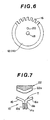
- each disc 12, 14 is made by stamping out a raw material sheet metal using a press die so that the teeth 16 are formed at the peripheral section of the disc 12, 14 as shown in Fig. 6. Otherwise, the teeth 16 may be formed by machining or cutting the peripheral section after each disc without teeth are stamped out.
- the tip portion 16a of each tooth 16 is bent outwardly, and thereafter the first and second discs 12, 14 are superposing at their back or main body 12a, 14a one on another in such a manner that the first and second discs 12, 14 are generally symmetrical with each other so that the bent tip portions 16a of the corresponding and facing teeth of the first and second discs 12, 14 extend in the opposite direction to each other and aligned with each other to constitute the above-mentioned combined tooth T which is parallel with the axis of the central opening 18.
- the first and second discs 12, 14 are united with each other by means of welding or the like, thus obtaining the pulley 10 for use with the cogged belt.
- the opening 20 for locating purpose may be used as a standard. Additionally, the thus located first and second discs 12, 14 may be temporarily connected with each other by means of spot-welding prior to the permanent uniting by the above welding.
- the overhang indicated by the dimension 1 1 in Fig. 5 can be made smaller.
- the pulley 10 is improved in rigidity as a whole although the above-mentioned dimension 1 1 is smaller.
- the dimension 1 2 indicated in Fig. 5 corresponds to the width of the tooth T which is in engagement with the cogged belt (not shown), thereby effectively preventing the cogged belt from disengaging therefrom.
- the discs 12, 14 are formed of so-called noise- suppression steel sheet made of ferromagnetic material, in order to further reduce its vibration level.
- Fig. 7 shows another embodiment of the pulley in accordance with the present invention, in which the tip portion 16a of each tooth 16 is so bent that an obtuse angle is formed between the tip portion 16a and the flat main body 12a, 14a.
- the tooth T constituted by the corresponding and facing teeth 16 becomes generally Y-shaped in cross-section as a whole.
- the cogged belt 22 can be effectively prevented from displacing in its lateral direction or the axial direction of the pulley 10, which is very effective for preventing the belt 22 from disengaging from the teeth T of the pulley 10.
- the tooth section. 22a of the belt 22 is formed of a material which is high in damping capacity, for example, natural rubber.
- finishing the teeth T may be accomplished by machining, particularly cutting or rolling, before and after the first and second discs 12, 14 are united as a single unit upon bending of the teeth 16 of each discs 12, 14, thereby improving the finishing accuracy of pulley teeth T.
- the machining is so simple and light as to merely modify the shape of the teeth which have been already formed, and therefore, it is sufficient that the steps for production are noticeably less.
- the pulley is produced by superposing the discs formed of sheet metal so that the discs are united to form a single unit.
- a high damping capacity material is interposed between a pair of the discs, the vibration of the pulley itself is effectively suppressed, thus preventing noise generation due to the pulley movement.
Landscapes
- Engineering & Computer Science (AREA)
- General Engineering & Computer Science (AREA)
- Mechanical Engineering (AREA)
- Physics & Mathematics (AREA)
- General Physics & Mathematics (AREA)
- Pulleys (AREA)
- Combination Of More Than One Step In Electrophotography (AREA)
- Control Or Security For Electrophotography (AREA)
Description
- The invention relates to a pulley for a cogged belt, said pulley being of the type as shown in GB-A-1 142 414. Such pulleys are used together with a cogged belt for driving, for example, a cam shaft of an automotive internal combustion engine. Furthermore, the invention relates to a method for the manufacture of the pulley.
- The above mentioned GB-A-1 142 414 shows a pulley comprising first and second discs formed of sheet metal and secured with each other to form a unitary structure. Each disc is formed at its peripheral section with a plurality of teeth and the peripheral sections of said first and second discs are so bent that the bent portion of the two discs project generally in the opposite direction to each other.
- However, each of the teeth shown in the above reference only include base portions and do not include a base portion which serves as a tooth in the pulley of the type used in a contemporary internal combustion engine. The conventional teeth project vertically from the bent peripheral sections of the two discs and, therefore, no groove is formed below the bottom level of each of said teeth. Furthermore, if the conventional pulley is used in engagement with a cogged belt of the type actually used, only two edge-like teeth will drivingly contact with the.cog of the cogged belt so that the cog is urgingly pushed at its mere two narrow surface sections. This will result in damage of the cogs of the belt, thereby shortening the life of the cogged belt.
- The invention as claimed is intended to remedy these drawbacks. It solves the problem of how to design a pulley which drivingly contacts with a considerably wide side surface of each cog of the cogged belt, preventing local contact with a cog of the cogged belt.
- The advantages offered by the invention as defined in claim 1 are mainly that each tooth of the inventive pulley includes a base portion integral with and extending radially and outwardly from a main body of each disc, and a bent tip portion integral with the base portion. The bent tip portion of each tooth of the first disc and the corresponding bent tip portion of the second disc extend generally in the opposite directions to each other. By virtue of the bent tip portion of the corresponding teeth of the first and second discs which bent portions form a generally T- or Y-shaped tooth, the above mentioned considerably wide surface area is formed at the side surface of the tooth and this prevents the cogged belt from excessive wear.
- In addition, by virtue of the base portion of each tooth a considerable depth is formed between the top surface of each tooth and the outer periphery of the main body of each disc. This depth provides a considerable deep groove which is formed between adjacent teeth. This groove is essential between the adjacent teeth of the pulley for driving a cam shaft of an automotive internal combustion engine. Without the above mentioned base portion, no groove is provided between the adjacent teeth and, therefore, each cog of the cogged belt would be out of engagement with the peripheral section of the pulley.
- Another aspect of the invention, namely a method of producing such a pulley, is claimed in independent claim 5.
- Particular embodiments of the invention are set out in the dependent claims.
- The two aspects of the present invention, namely the inventive pulley and the inventive method for the manufacture thereof, are described in detail below with reference to drawings which illustrate preferred embodiments thereof.
- Fig. 1 is a front elevation of a conventional pulley for use with a cogged belt;
- Fig. 2 is a cross-sectional view of the pulley of Fig. 1;
- Fig. 3 is a perspective view of a preferred embodiment of a pulley for use with a cogged pulley, in accordance with the present invention;
- Fig. 4 is a front elevation of the pulley of Fig. 3;
- Fig. 5 is a cross-sectional view of the pulley of Fig. 3;
- Fig. 6 is a front elevation of a disc with teeth before being bent; and
- Fig. 7 is a fragmentary sectional view showing another embodiment of the pulley in accordance with the present invention.
- To facilitate understanding the present invention, a brief reference will be made to a conventional pulley for use with a cogged belt (not shown), depicted in Figs. 1 and 2. Referring to Figs. 1 and 2, the pulley 1 is produced by rolling or hobbing a raw material, otherwise by die-casting sintering metal or the like into a predetermined shape.
- However, with such a conventional pulley for use with a cogged belt, it is necessary to increase the thickness of not only its boss section and its outer peripheral section where teeth are formed but also the pulley entire, from the standpoints of restriction in production method and of obtaining a predetermined strength. This unavoidably and directly provides an additional mass onto a crankshaft and a camshaft, while contributing to increase in weight and material cost. As a result, a baneful influence is exerted on the vibration of systems including the crankshaft and the camshaft. In case where the baneful influence is extreme, the natural frequency in the torsional vibration of the system is lowered so as to make its resonance vibration, thereby promoting the generation of engine oise.
- In view of the above description of the conventional pulley for use with a cogged belt, reference is made to Figs. 3 to 5, wherein a preferred embodiment of a pulley for use with a cogged belt (not shown) is illustrated by the '
reference numeral 10. Thepulley 10 comprises first andsecond discs main body second discs teeth 16 which are located at equal intervals throughout the entire periphery of the disc. Thetip portion 16a of eachtooth 16 is so bent as to extend outwardly in the direction generally perpendicular to the flatmain body disc tooth 16 includes a radially and outwardly extendingbase portion 16b. Additionally, it will be understood that thetip portions 16a of the corresponding and facing teeth of the first andsecond discs disc central hole 18 for connection with a crankshaft (not shown) or a camshaft (not shown), and with ahole 20 used for locating purpose which hole is positioned in the vicinity of the central -hole 18. - The above-mentioned
pulley 10 is, for example, produced as follows: First, eachdisc teeth 16 are formed at the peripheral section of thedisc teeth 16 may be formed by machining or cutting the peripheral section after each disc without teeth are stamped out. Subsequently, thetip portion 16a of eachtooth 16 is bent outwardly, and thereafter the first andsecond discs main body second discs bent tip portions 16a of the corresponding and facing teeth of the first andsecond discs central opening 18. In this state, the first andsecond discs pulley 10 for use with the cogged belt. - In locating the
teeth 16 so that thetip portions 16a of the corresponding teeth of the first andsecond discs second discs - With the thus arranged
pulley 10, the overhang indicated by the dimension 11 in Fig. 5 can be made smaller. In this connection, since the first andsecond discs pulley 10 is improved in rigidity as a whole although the above-mentioned dimension 11 is smaller. Furthermore, the dimension 12 indicated in Fig. 5 corresponds to the width of the tooth T which is in engagement with the cogged belt (not shown), thereby effectively preventing the cogged belt from disengaging therefrom. Moreover, it is preferable to interpose between the first andsecond discs pulley 10. It is also preferable that thediscs - Fig. 7 shows another embodiment of the pulley in accordance with the present invention, in which the
tip portion 16a of eachtooth 16 is so bent that an obtuse angle is formed between thetip portion 16a and the flatmain body teeth 16 becomes generally Y-shaped in cross-section as a whole. With this configuration, thecogged belt 22 can be effectively prevented from displacing in its lateral direction or the axial direction of thepulley 10, which is very effective for preventing thebelt 22 from disengaging from the teeth T of thepulley 10. This permits the strength of thebelt 22 itself to increase, thereby suppressing the vibration of the belt itself. In this case, in order to further increase such an effect, it is preferable that the tooth section. 22a of thebelt 22 is formed of a material which is high in damping capacity, for example, natural rubber. - It will be appreciated that, in the above-mentioned all embodiments, finishing the teeth T may be accomplished by machining, particularly cutting or rolling, before and after the first and
second discs teeth 16 of eachdiscs - As appreciated from the above, according to the present invention, the pulley is produced by superposing the discs formed of sheet metal so that the discs are united to form a single unit. This greatly contributes to the weight-lightening of the pulley itself and according to the weight-lightening of the engine, thereby suppressing to the minimum level the baneful influence upon the vibration characteristics of the crankshaft and the camshaft. Particularly in case where a high damping capacity material is interposed between a pair of the discs, the vibration of the pulley itself is effectively suppressed, thus preventing noise generation due to the pulley movement.
Claims (14)
Applications Claiming Priority (2)
| Application Number | Priority Date | Filing Date | Title |
|---|---|---|---|
| JP40430/81 | 1981-03-23 | ||
| JP56040430A JPS57155576A (en) | 1981-03-23 | 1981-03-23 | Operation controller in two revolutions one cycle system copying machine |
Publications (2)
| Publication Number | Publication Date |
|---|---|
| EP0061145A1 EP0061145A1 (en) | 1982-09-29 |
| EP0061145B1 true EP0061145B1 (en) | 1984-12-05 |
Family
ID=12580425
Family Applications (1)
| Application Number | Title | Priority Date | Filing Date |
|---|---|---|---|
| EP82102175A Expired EP0061145B1 (en) | 1981-03-23 | 1982-03-17 | Pulley for cogged belt and method for producing same |
Country Status (4)
| Country | Link |
|---|---|
| US (1) | US4555240A (en) |
| EP (1) | EP0061145B1 (en) |
| JP (1) | JPS57155576A (en) |
| DE (1) | DE3261421D1 (en) |
Families Citing this family (8)
| Publication number | Priority date | Publication date | Assignee | Title |
|---|---|---|---|---|
| JPS58170458A (en) * | 1982-09-06 | 1983-10-07 | Toyoshima Shoichi | Apparatus for preparation of fish paste product |
| JPS58170457A (en) * | 1982-09-06 | 1983-10-07 | Toyoshima Shoichi | Apparatus for cutting rod-shaped fish paste product to definite length |
| CH667293A5 (en) * | 1985-02-11 | 1988-09-30 | Sulzer Ag | WHEEL. |
| JPH087522B2 (en) * | 1988-05-31 | 1996-01-29 | シャープ株式会社 | Copier |
| JPH0816817B2 (en) * | 1988-07-08 | 1996-02-21 | シャープ株式会社 | Electrophotographic equipment |
| JPH11132314A (en) | 1997-04-18 | 1999-05-21 | Uni Sunstar Bv | Sprocket and manufacture thereof |
| US8136827B2 (en) | 2009-09-01 | 2012-03-20 | The Gates Corporation | Belt drive system |
| TWI577903B (en) * | 2015-05-27 | 2017-04-11 | 傳誠技研有限公司 | Belt and pulley with positioning structure |
Family Cites Families (10)
| Publication number | Priority date | Publication date | Assignee | Title |
|---|---|---|---|---|
| DE81141C (en) * | ||||
| US1017152A (en) * | 1910-04-09 | 1912-02-13 | American Pulley Co | Pulley. |
| US1771370A (en) * | 1926-04-13 | 1930-07-22 | Continental Diamond Fibre Co | Mechanical element |
| CH133880A (en) * | 1927-10-24 | 1929-06-30 | Bbc Brown Boveri & Cie | Sheet metal pulley. |
| US1852814A (en) * | 1930-05-21 | 1932-04-05 | Gen Electric | Metal hub and the like |
| US1852815A (en) * | 1930-08-29 | 1932-04-05 | Gen Electric | Metal hub and the like |
| US2729110A (en) * | 1953-05-07 | 1956-01-03 | Automatic Steel Products Inc | Sheet metal pulley construction for tooth grip belts |
| US2931094A (en) * | 1957-07-29 | 1960-04-05 | Teerlink James | Method of making sprocket |
| US3436801A (en) * | 1966-06-23 | 1969-04-08 | Pig Design Corp | Method of making geared pulley to eliminate burrs in pulley groove and to facilitate entry of belt into pulley |
| JPS5427501B2 (en) * | 1975-01-17 | 1979-09-10 |
-
1981
- 1981-03-23 JP JP56040430A patent/JPS57155576A/en active Pending
-
1982
- 1982-03-17 DE DE8282102175T patent/DE3261421D1/en not_active Expired
- 1982-03-17 EP EP82102175A patent/EP0061145B1/en not_active Expired
- 1982-03-22 US US06/360,423 patent/US4555240A/en not_active Expired - Fee Related
Also Published As
| Publication number | Publication date |
|---|---|
| JPS57155576A (en) | 1982-09-25 |
| EP0061145A1 (en) | 1982-09-29 |
| US4555240A (en) | 1985-11-26 |
| DE3261421D1 (en) | 1985-01-17 |
Similar Documents
| Publication | Publication Date | Title |
|---|---|---|
| US4630498A (en) | Laminated wheel assembly | |
| US9803738B2 (en) | Laminated sprocket assembly | |
| EP0061145B1 (en) | Pulley for cogged belt and method for producing same | |
| US4462269A (en) | Flywheel | |
| KR102667730B1 (en) | Decoupling ring for a planetary gear | |
| JP3905322B2 (en) | Silent chain | |
| US4719682A (en) | Method of forming a laminated wheel assembly | |
| JP2004053007A (en) | Torsion damper pulley | |
| US20090062051A1 (en) | Silent chain transmission device | |
| JPH022463B2 (en) | ||
| EP0073063B1 (en) | Crankshaft pulley of engine | |
| JPH07232237A (en) | Mold for piston | |
| JPH112312A (en) | Low noise vibration sprocket | |
| US4547179A (en) | Timing belt pulley and method of manufacture | |
| EP0426678A1 (en) | DEVICE FOR SUPPRESSING CRACKS IN A GEARBOX. | |
| CA1157296A (en) | Flywheel | |
| JP2004176853A (en) | Manufacturing method of element of belt for continuously variable transmission | |
| JP2004125054A (en) | FORGED GEAR, ITS MANUFACTURING METHOD, AND GEAR FORGING DIE | |
| JPH09269035A (en) | Silent chain | |
| JPS61103028A (en) | Power transmission block of endless belt | |
| JPH0942450A (en) | Combined oil ring and combination of it and piston | |
| JP2695032B2 (en) | Drive plate and manufacturing method thereof | |
| JPS6170245A (en) | V-belt | |
| JP2568997Y2 (en) | Helical gear | |
| JP2520982Y2 (en) | Toothed sintered pulley |
Legal Events
| Date | Code | Title | Description |
|---|---|---|---|
| PUAI | Public reference made under article 153(3) epc to a published international application that has entered the european phase |
Free format text: ORIGINAL CODE: 0009012 |
|
| 17P | Request for examination filed |
Effective date: 19820420 |
|
| AK | Designated contracting states |
Designated state(s): DE FR GB |
|
| GRAA | (expected) grant |
Free format text: ORIGINAL CODE: 0009210 |
|
| AK | Designated contracting states |
Designated state(s): DE FR GB |
|
| REF | Corresponds to: |
Ref document number: 3261421 Country of ref document: DE Date of ref document: 19850117 |
|
| ET | Fr: translation filed | ||
| RAP2 | Party data changed (patent owner data changed or rights of a patent transferred) |
Owner name: NISSAN MOTOR CO., LTD. |
|
| PLBE | No opposition filed within time limit |
Free format text: ORIGINAL CODE: 0009261 |
|
| STAA | Information on the status of an ep patent application or granted ep patent |
Free format text: STATUS: NO OPPOSITION FILED WITHIN TIME LIMIT |
|
| 26N | No opposition filed | ||
| PGFP | Annual fee paid to national office [announced via postgrant information from national office to epo] |
Ref country code: GB Payment date: 19910225 Year of fee payment: 10 |
|
| PGFP | Annual fee paid to national office [announced via postgrant information from national office to epo] |
Ref country code: FR Payment date: 19910307 Year of fee payment: 10 |
|
| PGFP | Annual fee paid to national office [announced via postgrant information from national office to epo] |
Ref country code: DE Payment date: 19910430 Year of fee payment: 10 |
|
| PG25 | Lapsed in a contracting state [announced via postgrant information from national office to epo] |
Ref country code: GB Effective date: 19920317 |
|
| GBPC | Gb: european patent ceased through non-payment of renewal fee | ||
| PG25 | Lapsed in a contracting state [announced via postgrant information from national office to epo] |
Ref country code: FR Effective date: 19921130 |
|
| PG25 | Lapsed in a contracting state [announced via postgrant information from national office to epo] |
Ref country code: DE Effective date: 19921201 |
|
| REG | Reference to a national code |
Ref country code: FR Ref legal event code: ST |