EP0060116A1 - Apparatus for measurement of heart-related parameters - Google Patents
Apparatus for measurement of heart-related parameters Download PDFInfo
- Publication number
- EP0060116A1 EP0060116A1 EP82301158A EP82301158A EP0060116A1 EP 0060116 A1 EP0060116 A1 EP 0060116A1 EP 82301158 A EP82301158 A EP 82301158A EP 82301158 A EP82301158 A EP 82301158A EP 0060116 A1 EP0060116 A1 EP 0060116A1
- Authority
- EP
- European Patent Office
- Prior art keywords
- cycle
- variation
- calculated
- ith
- data obtained
- Prior art date
- Legal status (The legal status is an assumption and is not a legal conclusion. Google has not performed a legal analysis and makes no representation as to the accuracy of the status listed.)
- Granted
Links
Images
Classifications
-
- A—HUMAN NECESSITIES
- A61—MEDICAL OR VETERINARY SCIENCE; HYGIENE
- A61B—DIAGNOSIS; SURGERY; IDENTIFICATION
- A61B5/00—Measuring for diagnostic purposes; Identification of persons
- A61B5/02—Detecting, measuring or recording pulse, heart rate, blood pressure or blood flow; Combined pulse/heart-rate/blood pressure determination; Evaluating a cardiovascular condition not otherwise provided for, e.g. using combinations of techniques provided for in this group with electrocardiography or electroauscultation; Heart catheters for measuring blood pressure
Definitions
- the invention relates to apparatus for determining the magnitude of heart-related parameters in a patient.
- apparatus for determining the magnitude of heart-related parameters in a patient comprising means for detecting blood volume variation in the patient and for providing a signal representative of amplitude of the blood volume; the blood volume variation being cyclic in nature whereby the signal comprises a cyclic curve having, in each cycle of variation; a variable slope, a maximum amplitude, a minimum amplitude, a time interval between said maximum amplitude and said minimum amplitude, and a pulse repetition period; means for measuring the time interval; and means for calculating the magnitude of selected ones of said parameters.
- PW is the blood volume pulse waveform as measured, for example, by a photoelectric plethysmograph as well known in the art.
- the X axis is in time units, and the Y axis is in electrical units such as volts.
- the blood volume variation is cyclical in nature so that PW is a cyclic curve having an instantaneous cycle rate (period), a maximum amplitude, a minimum amplitude, a time interval between the maximum and minimum, and a variable slope.
- Y iMIN is the minimum amplitude of Y in the ith cycle
- Y iMAX is the maximum amplitude of Y in the ith cycle.
- ⁇ Y is defined as Y MAX - Y MIN
- S i is the slope at any point in the ith cycle.
- T i is defined as the time interval between the maximum and minimum amplitudes of Y in the ith cycle, and T i is the instantaneous cycle rate (period), i.e., the cycle rate of the ith cycle or the time between the minimum of the ith cycle and the minimum of the (i +l)th cycle.
- Q i also expresses the ratio of the time interval between the occurrence of Y iMIN and Y iV over the time interval between the occurrence of Y iMIN and Y iMAX . Assuming that Y lMIN occurs at t lMIN , Y IV occurs at t IV , and Y lMAX occurs at t IMAX , then Thus, Q i could be determined by time measurements at the points of maximum blood volume, minimum blood volume, and the point of maximum slope of the blood volume curve.
- Slope is determined by the well known procedure of measuring an increment Ay associated with a selected increment of time ⁇ t. The value for the slope is then given by The procedure is performed at a plurality of points along the curve PW.
- Y iV The amplitude of the signal at the point of maximum slope S iMAX is designated as Y iV for the ith cycle.
- the amplitudes at these points are averaged to obtain a value for Y iV .
- K is a constant determined by calibration as discussed below.
- a particular function of AT which satisfies conditions for blood pressure measurements is ( ⁇ T i /a) b . ⁇ T i so that where
- Average arterial pressure during a cycle is defined as where
- the average arterial compliance during the ith cycle is the average arterial compliance of the ith cycle.
- the average cardiac output during the ith cycle is
- the average stroke volume during the ith cycle is
- the method of determining heart related parameters in accordance with the invention consists of the following steps:
- Y iMAX , Y iMIN ⁇ T i , T i ' S i MAX and Y iV are measured.
- Heart related fuctions are then calculated with the above expressions and equations.
- the calculations may be performed manually, mechanically or electronically.
- data may be fed to an appropriately programmed general purpose computer or, as per a preferred embodiment of the invention, a microcomputer may be designed to both determine slope and maximum slope, and to perform the requisite calculations.
- each cycle of the signal PW constitutes a separate heart beat.
- the values for the parameters are determined by taking measurements in a plurality of heart beats, obtaining values for each heart beat, and then obtaining average values.
- the selected heart beats may be either consecutive beats, alternating beats, or randomly selected beats.
- 1 is a transducer for detecting blood volume in a patient and for providing an electrical signal representative of the blood volume at the output, such as, for example, a photoelectric plethysmograph.
- 5 is an amplifier which amplifies the output of 1 to provide at its output the varying magnitude Y. This output is fed to MAX detector 7 and MIN detector 9 which detect the maximum and minimum, respectively, of Y, and the times of occurrence thereof. The times are fed to subtractor 11 and the amplitudes are fed to calculator 13. The output of 11 is also fed to 13. It will be appreciated that the inputs to 11 could be fed directly to 13 which could perform the subtraction function.
- the output of 5 is also fed to a slope detector 15 which detects the maximum slope of PW and the amplitude of Y (Y iV ) associated with the maximum slope. This amplitude is also fed to 13.
- the function blocks 7 to 15 may be implemented either by electronic hardware or by software in a computer or microcomputer, or a combination of both.
- all of the blocks 5 to 15 are made up as a single unit including a microcomputer for the blocks 7 to 15.
- the single unit has an input terminal to receive an output terminal of the transducer 1, and an output means for connection to a display device.
- the display device can constitute a part of the single unit.
- Pp is determined by an alternate method (using, for example, the cuff apparatus employed by physicians in examining their patients). Measurements of maximum and minimum signal amplitudes, as well as amplitude at maximum slope, are then taken, and these amplitudes, and the value of P are used to determine the value of K from expression (1) above. As long as the bandwidth of the amplifier 5 remains constant, the apparatus does not have to be recalibrated under normal conditions.
- the unit may need to be recalibrated for a particular patient if that patient suffers from atherosclerosis or other obstructive circulatory condition.
- the calibration needs to be done only once during a period of time during which the energy loss due to atherosclerosis does not change substantially.
- the unit includes an automatic calculator, e.g., a microcomputer, it can be programmed to automatically perform the calibration step.
- an automatic calculator e.g., a microcomputer
Landscapes
- Health & Medical Sciences (AREA)
- Life Sciences & Earth Sciences (AREA)
- Biomedical Technology (AREA)
- Heart & Thoracic Surgery (AREA)
- Physiology (AREA)
- Biophysics (AREA)
- Pathology (AREA)
- Engineering & Computer Science (AREA)
- Cardiology (AREA)
- Physics & Mathematics (AREA)
- Medical Informatics (AREA)
- Molecular Biology (AREA)
- Surgery (AREA)
- Animal Behavior & Ethology (AREA)
- General Health & Medical Sciences (AREA)
- Public Health (AREA)
- Veterinary Medicine (AREA)
- Measuring Pulse, Heart Rate, Blood Pressure Or Blood Flow (AREA)
Abstract
Description
- The invention relates to apparatus for determining the magnitude of heart-related parameters in a patient.
- Known in the art are non-invasive methods and apparatus for determining the magnitude of the heart-related parameters arterial systolic and diastolic pressure. Such a method and apparatus are taught in my U.S. Patent 4,030,485. However, in this method and apparatus, it is necessary to perform a calibration procedure for each patient which is inconvenient and can lead to errors. In addition, using the methods and apparatus presently available, each heart-related parameter, such as arterial pressure, heart rate, peripheral resistance, etc., must be separately measured using separate instruments and methods. This is especially inconvenient when the parameters must be monitored remotely and on a continuous basis.
- It is therefore an object of the invention to provide apparatus for determining the magnitude of heart-related functions wherein, with a single instrument, it is possible to determine a plurality of such heart-related parameters.
- It is a further object of the invention to provide such apparatus normally requiring only a single factory calibration procedure.
- In accordance with the invention, apparatus for determining the magnitude of heart-related parameters in a patient comprising means for detecting blood volume variation in the patient and for providing a signal representative of amplitude of the blood volume; the blood volume variation being cyclic in nature whereby the signal comprises a cyclic curve having, in each cycle of variation; a variable slope, a maximum amplitude, a minimum amplitude, a time interval between said maximum amplitude and said minimum amplitude, and a pulse repetition period; means for measuring the time interval; and means for calculating the magnitude of selected ones of said parameters.
- Reference is now made to the accompanying drawings, in which:-
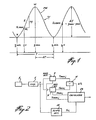
- Figure 1 is a graph useful in explaining the invention; and
- Figure 2 is a functional block diagram of an apparatus in accordance with the invention.
- Referring to Figure 1, PW is the blood volume pulse waveform as measured, for example, by a photoelectric plethysmograph as well known in the art. The X axis is in time units, and the Y axis is in electrical units such as volts.
- As is known, the blood volume variation is cyclical in nature so that PW is a cyclic curve having an instantaneous cycle rate (period), a maximum amplitude, a minimum amplitude, a time interval between the maximum and minimum, and a variable slope. YiMIN is the minimum amplitude of Y in the ith cycle, and YiMAX is the maximum amplitude of Y in the ith cycle. ΔY is defined as YMAX - YMIN, Si is the slope at any point in the ith cycle. Δ Ti is defined as the time interval between the maximum and minimum amplitudes of Y in the ith cycle, and Ti is the instantaneous cycle rate (period), i.e., the cycle rate of the ith cycle or the time between the minimum of the ith cycle and the minimum of the (i +l)th cycle.
- It will, of course, be appreciated that Qi also expresses the ratio of the time interval between the occurrence of YiMIN and YiV over the time interval between the occurrence of YiMIN and YiMAX. Assuming that YlMIN occurs at tlMIN, YIV occurs at tIV, and YlMAX occurs at tIMAX, then

- Slope is determined by the well known procedure of measuring an increment Ay associated with a selected increment of time Δt. The value for the slope is then given by

- The amplitude of the signal at the point of maximum slope SiMAX is designated as YiV for the ith cycle. In cases where measurements indicate maximum slopes at a plurality of points, the amplitudes at these points are averaged to obtain a value for YiV. Thus, if n points are indicated as having the same maximum slope, YiV is given by

where Ppi = pulse pressure as determined by measurements in the ith cycle as discussed below. - The relationship between Ppi and Qi depends on elastic properties of the extensible tube (in this case, an artery). A particular function for such an extensible tube is
- Ppi= K(Qi/I-Qi) mm Hg (1) where
- K is a constant determined by calibration as discussed below.
- Thus, by determining the maximum slope, and by measuring the amplitude of Y at the point of maximum slope, and the maximum and minimum amplitudes of Y, it is possible, in accordance with the invention, to determine pulse pressure.
- It is also known that


- Ps = arterial systolic pressure;
- Pd = arterial diastolic pressure; and
- τ = an arterial timing constant. τ is given by:

- A particular function of AT which satisfies conditions for blood pressure measurements is (ΔTi/a)b.ΔTi so that

- τi is the average arterial time constant during the ith cycle; and
- a and b are constants. In a particular case, a = 0.1 and b = 0.19.
- In a second case,
- b = g Pp g = 0.003
- a = .05 Pp = Pulse pressure
- Arterial systolic pressure as determined from measurements in an ith cycle, is given by the expression:

- A particular function J'(ΔT) which is valid is
- Po = mm Hg
- Po' = 40 mm Hg
- T = constant = 1 sec.
- Using equations 1 and 3 after obtaining the magnitude of ΔT, it is possible to obtain values for both systolic and diastolic pressure.
- It is also known that instantaneous heart rate, using data obtained in the ith cycle, may be calculated using the equation:
- HRi = 60/Ti beats per min.
- Average arterial pressure during a cycle is defined as

- Pm' = effective average arterial pressure during a cycle.
- Average Total Periopheral Resistance during the ith cycle is


- The average arterial compliance during the ith cycle is

- The average cardiac output during the ith cycle is

- The average stroke volume during the ith cycle is

- The method of determining heart related parameters in accordance with the invention, consists of the following steps:
- The calibration constant K must first be determined. As this constant need be determined only once, it does not constitute one of the steps generally involved, and the method of determining K will be more fully discussed below in the discussion of apparatus for carrying out the invention.
- In any ith cycle, YiMAX, YiMINΔTi, Ti' SiMAX and YiV are measured. Heart related fuctions are then calculated with the above expressions and equations. The calculations may be performed manually, mechanically or electronically. In the electronic option, data may be fed to an appropriately programmed general purpose computer or, as per a preferred embodiment of the invention, a microcomputer may be designed to both determine slope and maximum slope, and to perform the requisite calculations.
- As will be appreciated, each cycle of the signal PW constitutes a separate heart beat. Preferably, the values for the parameters are determined by taking measurements in a plurality of heart beats, obtaining values for each heart beat, and then obtaining average values. The selected heart beats may be either consecutive beats, alternating beats, or randomly selected beats.
- Turning now to Figure 2, 1 is a transducer for detecting blood volume in a patient and for providing an electrical signal representative of the blood volume at the output, such as, for example, a photoelectric plethysmograph. 5 is an amplifier which amplifies the output of 1 to provide at its output the varying magnitude Y. This output is fed to
MAX detector 7 and MIN detector 9 which detect the maximum and minimum, respectively, of Y, and the times of occurrence thereof. The times are fed tosubtractor 11 and the amplitudes are fed tocalculator 13. The output of 11 is also fed to 13. It will be appreciated that the inputs to 11 could be fed directly to 13 which could perform the subtraction function. - The output of 5 is also fed to a slope detector 15 which detects the maximum slope of PW and the amplitude of Y (YiV) associated with the maximum slope. This amplitude is also fed to 13.
- The function blocks 7 to 15 may be implemented either by electronic hardware or by software in a computer or microcomputer, or a combination of both. Preferably, all of the blocks 5 to 15 are made up as a single unit including a microcomputer for the
blocks 7 to 15. The single unit has an input terminal to receive an output terminal of the transducer 1, and an output means for connection to a display device. Alternatively, the display device can constitute a part of the single unit. - To calibrate the unit, Pp, is determined by an alternate method (using, for example, the cuff apparatus employed by physicians in examining their patients). Measurements of maximum and minimum signal amplitudes, as well as amplitude at maximum slope, are then taken, and these amplitudes, and the value of P are used to determine the value of K from expression (1) above. As long as the bandwidth of the amplifier 5 remains constant, the apparatus does not have to be recalibrated under normal conditions.
- The unit may need to be recalibrated for a particular patient if that patient suffers from atherosclerosis or other obstructive circulatory condition. The calibration needs to be done only once during a period of time during which the energy loss due to atherosclerosis does not change substantially.
- If the unit includes an automatic calculator, e.g., a microcomputer, it can be programmed to automatically perform the calibration step.
where
Claims (11)
Ti = time interval (period) of said selected cycle of variation.


Priority Applications (1)
| Application Number | Priority Date | Filing Date | Title |
|---|---|---|---|
| AT82301158T ATE16240T1 (en) | 1981-03-11 | 1982-03-08 | DEVICE FOR MEASURING CIRCUIT PARAMETERS. |
Applications Claiming Priority (2)
| Application Number | Priority Date | Filing Date | Title |
|---|---|---|---|
| US242568 | 1981-03-11 | ||
| US06/242,568 US4418700A (en) | 1981-03-11 | 1981-03-11 | Method and apparatus for measurement of heart-related parameters |
Publications (2)
| Publication Number | Publication Date |
|---|---|
| EP0060116A1 true EP0060116A1 (en) | 1982-09-15 |
| EP0060116B1 EP0060116B1 (en) | 1985-10-30 |
Family
ID=22915320
Family Applications (1)
| Application Number | Title | Priority Date | Filing Date |
|---|---|---|---|
| EP82301158A Expired EP0060116B1 (en) | 1981-03-11 | 1982-03-08 | Apparatus for measurement of heart-related parameters |
Country Status (5)
| Country | Link |
|---|---|
| US (1) | US4418700A (en) |
| EP (1) | EP0060116B1 (en) |
| AT (1) | ATE16240T1 (en) |
| CA (1) | CA1183904A (en) |
| DE (1) | DE3267091D1 (en) |
Cited By (6)
| Publication number | Priority date | Publication date | Assignee | Title |
|---|---|---|---|---|
| WO1985000279A1 (en) * | 1983-06-30 | 1985-01-31 | Sri International | Method and apparatus for diagnosis of coronary artery disease |
| EP0160994A2 (en) * | 1984-05-10 | 1985-11-13 | Warner, Sylvia | Heart-related parameters monitoring apparatus |
| EP0393228A1 (en) * | 1989-04-21 | 1990-10-24 | Glenfield Warner | Heart-related parameters monitoring apparatus |
| EP0434399A1 (en) * | 1989-12-20 | 1991-06-26 | Critikon, Inc. | Peripheral arterial monitoring instruments |
| US5865758A (en) * | 1997-01-24 | 1999-02-02 | Nite Q Ltd | System for obtaining hemodynamic information |
| WO2017222732A1 (en) * | 2016-06-24 | 2017-12-28 | Qualcomm Incorporated | Dynamic calibration of a blood pressure measurement device |
Families Citing this family (33)
| Publication number | Priority date | Publication date | Assignee | Title |
|---|---|---|---|---|
| US4718428A (en) * | 1984-02-17 | 1988-01-12 | Cortronic Corporation | Method for determining diastolic arterial blood pressure in a subject |
| US4718427A (en) * | 1984-02-17 | 1988-01-12 | Cortronic Corporation | Method for determining systolic arterial blood pressure in a subject |
| US4669485A (en) * | 1984-02-17 | 1987-06-02 | Cortronic Corporation | Apparatus and method for continuous non-invasive cardiovascular monitoring |
| US4718426A (en) * | 1984-02-17 | 1988-01-12 | Cortronic Corporation | Method for determining diastolic arterial blood pressure in a subject |
| EP0154995B1 (en) * | 1984-03-13 | 1990-09-19 | Omron Tateisi Electronics Co. | Device for measuring blood pressure |
| US4649928A (en) * | 1985-10-21 | 1987-03-17 | Gms Engineering Corporation | Noise-immune blood pressure measurement technique and system |
| JPS62233142A (en) * | 1986-04-03 | 1987-10-13 | テルモ株式会社 | Blood pressure measuring device |
| US4858618A (en) * | 1986-05-23 | 1989-08-22 | Baxter Travenol Laboratories, Inc. | Thermodilution method and apparatus for determining right ventricular ejection fraction |
| US4727884A (en) * | 1986-05-28 | 1988-03-01 | Link William T | Technique for obtaining the mean blood pressure constant for an individual's blood pressure |
| DE68908225T2 (en) * | 1988-03-15 | 1994-04-07 | Omron Tateisi Electronics Co | Electronic blood pressure monitor. |
| US4940059A (en) * | 1988-03-21 | 1990-07-10 | Lafayette Instrument Co., Inc. | Polygraph with improved cardiac monitoring |
| US5178151A (en) * | 1988-04-20 | 1993-01-12 | Sackner Marvin A | System for non-invasive detection of changes of cardiac volumes and aortic pulses |
| CA1327631C (en) * | 1989-03-20 | 1994-03-08 | Non-Invasive Monitoring Systems, Inc. | System for non-invasive detection of changes of cardiac volumes and aortic pulses |
| US5299120A (en) * | 1989-09-15 | 1994-03-29 | Hewlett-Packard Company | Method for digitally processing signals containing information regarding arterial blood flow |
| US5140990A (en) * | 1990-09-06 | 1992-08-25 | Spacelabs, Inc. | Method of measuring blood pressure with a photoplethysmograph |
| US5720292A (en) * | 1996-07-31 | 1998-02-24 | Medwave, Inc. | Beat onset detector |
| US5865755A (en) * | 1996-10-11 | 1999-02-02 | Dxtek, Inc. | Method and apparatus for non-invasive, cuffless, continuous blood pressure determination |
| US6986744B1 (en) | 1999-02-02 | 2006-01-17 | Transonic Systems, Inc. | Method and apparatus for determining blood flow during a vascular corrective procedure |
| US6616613B1 (en) | 2000-04-27 | 2003-09-09 | Vitalsines International, Inc. | Physiological signal monitoring system |
| US20050075542A1 (en) * | 2000-12-27 | 2005-04-07 | Rami Goldreich | System and method for automatic monitoring of the health of a user |
| EP1379167A1 (en) * | 2001-04-06 | 2004-01-14 | Medic4all Inc. | A physiological monitoring system for a computational device of a human subject |
| US20030107487A1 (en) | 2001-12-10 | 2003-06-12 | Ronen Korman | Method and device for measuring physiological parameters at the wrist |
| JP3872371B2 (en) * | 2002-03-29 | 2007-01-24 | セイコーインスツル株式会社 | Portable biological information collecting apparatus, biological information collecting system, and biological information collecting method |
| US7738935B1 (en) | 2002-07-09 | 2010-06-15 | Pacesetter, Inc. | Methods and devices for reduction of motion-induced noise in pulse oximetry |
| US6997879B1 (en) | 2002-07-09 | 2006-02-14 | Pacesetter, Inc. | Methods and devices for reduction of motion-induced noise in optical vascular plethysmography |
| WO2005018446A1 (en) * | 2003-08-13 | 2005-03-03 | Zakrytoe Aktsionernoe Obschestvo 'technologicheskie Resheniya E.M.' | Method for volumetric compression oscillometry for determining blood circulatory system parameters |
| US20060047214A1 (en) * | 2004-08-24 | 2006-03-02 | Jacob Fraden | Wireless medical probe |
| US7544168B2 (en) * | 2004-09-30 | 2009-06-09 | Jerusalem College Of Technology | Measuring systolic blood pressure by photoplethysmography |
| US8328728B2 (en) * | 2008-08-22 | 2012-12-11 | Pacesetter, Inc. | Implantable hemodynamic monitor and methods for use therewith |
| ES2336997B1 (en) | 2008-10-16 | 2011-06-13 | Sabirmedical,S.L. | SYSTEM AND APPARATUS FOR NON-INVASIVE MEASUREMENT OF BLOOD PRESSURE. |
| FR2940039B1 (en) * | 2008-12-19 | 2011-11-25 | Ass Enseignement Tech Superieur Groupe Esaip | METHOD FOR MEASURING AN INDEX OF THE LOCAL RIGIDITY OF THE WALL OF A CONDUCTION ARTERY AND CORRESPONDING INSTALLATION |
| CN102613964B (en) * | 2012-03-12 | 2013-12-25 | 深圳市视聆科技开发有限公司 | Method and system for acquiring physiological signal cycle |
| WO2016065469A1 (en) | 2014-10-27 | 2016-05-06 | Jesse Goodman | System and method for monitoring aortic pulse wave velocity and blood pressure |
Citations (1)
| Publication number | Priority date | Publication date | Assignee | Title |
|---|---|---|---|---|
| US4245648A (en) * | 1978-09-20 | 1981-01-20 | Trimmer Gordon A | Method and apparatus for measuring blood pressure and pulse rate |
Family Cites Families (6)
| Publication number | Priority date | Publication date | Assignee | Title |
|---|---|---|---|---|
| US3908639A (en) * | 1971-04-02 | 1975-09-30 | Kevin M Mcintyre | Detecting impaired heart mechanical performance |
| JPS5033676A (en) * | 1973-07-30 | 1975-03-31 | ||
| US4030485A (en) * | 1974-11-12 | 1977-06-21 | Glenfield Warner | Method and apparatus for continuously monitoring systolic blood pressure |
| US4137910A (en) * | 1976-09-30 | 1979-02-06 | Murphy Donald H | Method and means for measuring cardiac pumping performance of left ventricle |
| SU728833A1 (en) * | 1977-09-05 | 1980-04-25 | Предприятие П/Я А-3361 | Apparatus for measuring blood-flow time-interval |
| US4203451A (en) * | 1978-03-17 | 1980-05-20 | Panico Joseph J | Cardiovascular analysis, method and apparatus |
-
1981
- 1981-03-11 US US06/242,568 patent/US4418700A/en not_active Expired - Lifetime
-
1982
- 1982-02-10 CA CA000395969A patent/CA1183904A/en not_active Expired
- 1982-03-08 EP EP82301158A patent/EP0060116B1/en not_active Expired
- 1982-03-08 AT AT82301158T patent/ATE16240T1/en not_active IP Right Cessation
- 1982-03-08 DE DE8282301158T patent/DE3267091D1/en not_active Expired
Patent Citations (1)
| Publication number | Priority date | Publication date | Assignee | Title |
|---|---|---|---|---|
| US4245648A (en) * | 1978-09-20 | 1981-01-20 | Trimmer Gordon A | Method and apparatus for measuring blood pressure and pulse rate |
Non-Patent Citations (2)
| Title |
|---|
| PROCEEDINGS OF THE IEEE, vol. 65, no. 5, May 1977, pages 696-702, New York (USA); * |
| WESCON TECHNICAL PAPERS, vol. 16, part 12/1, 1972, pages 1-7, Los Angeles (USA); * |
Cited By (8)
| Publication number | Priority date | Publication date | Assignee | Title |
|---|---|---|---|---|
| WO1985000279A1 (en) * | 1983-06-30 | 1985-01-31 | Sri International | Method and apparatus for diagnosis of coronary artery disease |
| EP0160994A2 (en) * | 1984-05-10 | 1985-11-13 | Warner, Sylvia | Heart-related parameters monitoring apparatus |
| EP0160994A3 (en) * | 1984-05-10 | 1987-02-04 | Warner, Sylvia | Heart-related parameters monitoring apparatus |
| EP0393228A1 (en) * | 1989-04-21 | 1990-10-24 | Glenfield Warner | Heart-related parameters monitoring apparatus |
| EP0434399A1 (en) * | 1989-12-20 | 1991-06-26 | Critikon, Inc. | Peripheral arterial monitoring instruments |
| US5865758A (en) * | 1997-01-24 | 1999-02-02 | Nite Q Ltd | System for obtaining hemodynamic information |
| WO2017222732A1 (en) * | 2016-06-24 | 2017-12-28 | Qualcomm Incorporated | Dynamic calibration of a blood pressure measurement device |
| US11337657B2 (en) | 2016-06-24 | 2022-05-24 | Philips Healthcare Informatics, Inc. | Dynamic calibration of a blood pressure measurement device |
Also Published As
| Publication number | Publication date |
|---|---|
| CA1183904A (en) | 1985-03-12 |
| EP0060116B1 (en) | 1985-10-30 |
| DE3267091D1 (en) | 1985-12-05 |
| ATE16240T1 (en) | 1985-11-15 |
| US4418700A (en) | 1983-12-06 |
Similar Documents
| Publication | Publication Date | Title |
|---|---|---|
| EP0060116B1 (en) | Apparatus for measurement of heart-related parameters | |
| US4907596A (en) | Blood pressure measuring appliance | |
| USRE37852E1 (en) | Blood pressure monitoring system | |
| US5241966A (en) | Method and apparatus for measuring cardiac output | |
| CN100528073C (en) | Arterial pressure-based, automatic determination of a cardiovascular parameter | |
| CA1334211C (en) | Method and apparatus for continuously and non-invasively measuring the blood pressure of a patient | |
| EP0498885B1 (en) | A method of measuring blood pressure with a photoplethysmograph | |
| US4245648A (en) | Method and apparatus for measuring blood pressure and pulse rate | |
| Nabeel et al. | Arterial blood pressure estimation from local pulse wave velocity using dual-element photoplethysmograph probe | |
| US5873834A (en) | Blood pressure detecting device | |
| US6083171A (en) | Blood pressure monitoring apparatus | |
| US4676253A (en) | Method and apparatus for noninvasive determination of cardiac output | |
| US7137955B2 (en) | Methods and systems for distal recording of phonocardiographic signals | |
| US6266558B1 (en) | Apparatus and method for nerve conduction measurements with automatic setting of stimulus intensity | |
| US6929610B2 (en) | Non-invasive measurement of blood pressure | |
| US6623434B2 (en) | Method and instrument to measure vascular impedance | |
| US4834107A (en) | Heart-related parameters monitoring apparatus | |
| US8679025B2 (en) | Method for determination of cardiac output | |
| US20020151805A1 (en) | Blood flow volume measurement method and vital sign monitoring apparatus | |
| US6348038B1 (en) | Method and apparatus for the measurement of cardiac output | |
| JPH0462737B2 (en) | ||
| US6517495B1 (en) | Automatic indirect non-invasive apparatus and method for determining diastolic blood pressure by calibrating an oscillation waveform | |
| EP0698370B1 (en) | Blood-pressure monitor apparatus | |
| WO1992006633A1 (en) | Method and apparatus for measuring cardiac output | |
| US20200178816A1 (en) | System for determining coronary pulse wave velocity |
Legal Events
| Date | Code | Title | Description |
|---|---|---|---|
| PUAI | Public reference made under article 153(3) epc to a published international application that has entered the european phase |
Free format text: ORIGINAL CODE: 0009012 |
|
| AK | Designated contracting states |
Designated state(s): AT BE CH DE FR GB IT LU NL SE |
|
| 17P | Request for examination filed |
Effective date: 19830309 |
|
| GRAA | (expected) grant |
Free format text: ORIGINAL CODE: 0009210 |
|
| AK | Designated contracting states |
Designated state(s): AT BE CH DE FR GB IT LI LU NL SE |
|
| PG25 | Lapsed in a contracting state [announced via postgrant information from national office to epo] |
Ref country code: SE Effective date: 19851030 Ref country code: NL Effective date: 19851030 Ref country code: LI Effective date: 19851030 Ref country code: IT Free format text: LAPSE BECAUSE OF FAILURE TO SUBMIT A TRANSLATION OF THE DESCRIPTION OR TO PAY THE FEE WITHIN THE PRESCRIBED TIME-LIMIT;WARNING: LAPSES OF ITALIAN PATENTS WITH EFFECTIVE DATE BEFORE 2007 MAY HAVE OCCURRED AT ANY TIME BEFORE 2007. THE CORRECT EFFECTIVE DATE MAY BE DIFFERENT FROM THE ONE RECORDED. Effective date: 19851030 Ref country code: FR Free format text: THE PATENT HAS BEEN ANNULLED BY A DECISION OF A NATIONAL AUTHORITY Effective date: 19851030 Ref country code: CH Effective date: 19851030 Ref country code: BE Effective date: 19851030 Ref country code: AT Effective date: 19851030 |
|
| REF | Corresponds to: |
Ref document number: 16240 Country of ref document: AT Date of ref document: 19851115 Kind code of ref document: T |
|
| REF | Corresponds to: |
Ref document number: 3267091 Country of ref document: DE Date of ref document: 19851205 |
|
| REG | Reference to a national code |
Ref country code: CH Ref legal event code: PL |
|
| EN | Fr: translation not filed | ||
| PG25 | Lapsed in a contracting state [announced via postgrant information from national office to epo] |
Ref country code: LU Free format text: LAPSE BECAUSE OF NON-PAYMENT OF DUE FEES Effective date: 19860331 |
|
| NLV1 | Nl: lapsed or annulled due to failure to fulfill the requirements of art. 29p and 29m of the patents act | ||
| PLBE | No opposition filed within time limit |
Free format text: ORIGINAL CODE: 0009261 |
|
| STAA | Information on the status of an ep patent application or granted ep patent |
Free format text: STATUS: NO OPPOSITION FILED WITHIN TIME LIMIT |
|
| 26N | No opposition filed | ||
| PGFP | Annual fee paid to national office [announced via postgrant information from national office to epo] |
Ref country code: GB Payment date: 19950227 Year of fee payment: 14 |
|
| PGFP | Annual fee paid to national office [announced via postgrant information from national office to epo] |
Ref country code: DE Payment date: 19950309 Year of fee payment: 14 |
|
| PG25 | Lapsed in a contracting state [announced via postgrant information from national office to epo] |
Ref country code: GB Effective date: 19960308 |
|
| GBPC | Gb: european patent ceased through non-payment of renewal fee |
Effective date: 19960308 |
|
| PG25 | Lapsed in a contracting state [announced via postgrant information from national office to epo] |
Ref country code: DE Effective date: 19961203 |