EP0060069B1 - A probe and a system for detecting wear of refractory wall - Google Patents
A probe and a system for detecting wear of refractory wall Download PDFInfo
- Publication number
- EP0060069B1 EP0060069B1 EP82301045A EP82301045A EP0060069B1 EP 0060069 B1 EP0060069 B1 EP 0060069B1 EP 82301045 A EP82301045 A EP 82301045A EP 82301045 A EP82301045 A EP 82301045A EP 0060069 B1 EP0060069 B1 EP 0060069B1
- Authority
- EP
- European Patent Office
- Prior art keywords
- probe
- circuit
- elements
- refractory wall
- probe elements
- Prior art date
- Legal status (The legal status is an assumption and is not a legal conclusion. Google has not performed a legal analysis and makes no representation as to the accuracy of the status listed.)
- Expired
Links
- 239000000523 sample Substances 0.000 title claims description 163
- 238000001514 detection method Methods 0.000 claims description 43
- 239000002184 metal Substances 0.000 claims description 28
- 229910052751 metal Inorganic materials 0.000 claims description 28
- 238000002844 melting Methods 0.000 claims description 20
- 230000008018 melting Effects 0.000 claims description 20
- 238000007664 blowing Methods 0.000 claims description 19
- 239000000463 material Substances 0.000 claims description 19
- 238000012545 processing Methods 0.000 claims description 7
- 239000007789 gas Substances 0.000 description 23
- 238000000034 method Methods 0.000 description 12
- 230000035945 sensitivity Effects 0.000 description 10
- 229910000831 Steel Inorganic materials 0.000 description 8
- 238000010586 diagram Methods 0.000 description 8
- 239000011819 refractory material Substances 0.000 description 8
- 239000010959 steel Substances 0.000 description 8
- 239000000945 filler Substances 0.000 description 7
- QVGXLLKOCUKJST-UHFFFAOYSA-N atomic oxygen Chemical compound [O] QVGXLLKOCUKJST-UHFFFAOYSA-N 0.000 description 6
- 239000001301 oxygen Substances 0.000 description 6
- 229910052760 oxygen Inorganic materials 0.000 description 6
- 230000000750 progressive effect Effects 0.000 description 6
- 230000002159 abnormal effect Effects 0.000 description 5
- CPLXHLVBOLITMK-UHFFFAOYSA-N Magnesium oxide Chemical compound [Mg]=O CPLXHLVBOLITMK-UHFFFAOYSA-N 0.000 description 4
- 230000001681 protective effect Effects 0.000 description 4
- 239000003990 capacitor Substances 0.000 description 3
- 230000008021 deposition Effects 0.000 description 3
- 238000012544 monitoring process Methods 0.000 description 3
- 230000008569 process Effects 0.000 description 3
- 238000012546 transfer Methods 0.000 description 3
- 239000000956 alloy Substances 0.000 description 2
- 230000008859 change Effects 0.000 description 2
- 238000006243 chemical reaction Methods 0.000 description 2
- 238000010276 construction Methods 0.000 description 2
- 230000000694 effects Effects 0.000 description 2
- 238000005286 illumination Methods 0.000 description 2
- 239000011810 insulating material Substances 0.000 description 2
- 239000000395 magnesium oxide Substances 0.000 description 2
- 239000000155 melt Substances 0.000 description 2
- 239000000203 mixture Substances 0.000 description 2
- 238000012986 modification Methods 0.000 description 2
- 230000004048 modification Effects 0.000 description 2
- 230000008439 repair process Effects 0.000 description 2
- 239000002893 slag Substances 0.000 description 2
- 238000002791 soaking Methods 0.000 description 2
- 239000000126 substance Substances 0.000 description 2
- 229910000809 Alumel Inorganic materials 0.000 description 1
- 229910001006 Constantan Inorganic materials 0.000 description 1
- 229910000805 Pig iron Inorganic materials 0.000 description 1
- 238000007792 addition Methods 0.000 description 1
- 229910045601 alloy Inorganic materials 0.000 description 1
- 230000004075 alteration Effects 0.000 description 1
- 230000003321 amplification Effects 0.000 description 1
- 238000004458 analytical method Methods 0.000 description 1
- 238000000429 assembly Methods 0.000 description 1
- 230000000712 assembly Effects 0.000 description 1
- 239000011449 brick Substances 0.000 description 1
- 229910001179 chromel Inorganic materials 0.000 description 1
- 230000000295 complement effect Effects 0.000 description 1
- 239000004020 conductor Substances 0.000 description 1
- 238000001816 cooling Methods 0.000 description 1
- 125000004122 cyclic group Chemical group 0.000 description 1
- 230000007423 decrease Effects 0.000 description 1
- 230000000881 depressing effect Effects 0.000 description 1
- 230000003628 erosive effect Effects 0.000 description 1
- 238000002474 experimental method Methods 0.000 description 1
- 239000011261 inert gas Substances 0.000 description 1
- 238000005259 measurement Methods 0.000 description 1
- 238000003199 nucleic acid amplification method Methods 0.000 description 1
- 230000002688 persistence Effects 0.000 description 1
- 230000009467 reduction Effects 0.000 description 1
- 238000007670 refining Methods 0.000 description 1
- 230000004044 response Effects 0.000 description 1
- 230000002441 reversible effect Effects 0.000 description 1
- 230000000630 rising effect Effects 0.000 description 1
- 230000035939 shock Effects 0.000 description 1
Images





Classifications
-
- C—CHEMISTRY; METALLURGY
- C21—METALLURGY OF IRON
- C21B—MANUFACTURE OF IRON OR STEEL
- C21B7/00—Blast furnaces
- C21B7/04—Blast furnaces with special refractories
- C21B7/06—Linings for furnaces
-
- C—CHEMISTRY; METALLURGY
- C21—METALLURGY OF IRON
- C21B—MANUFACTURE OF IRON OR STEEL
- C21B7/00—Blast furnaces
- C21B7/24—Test rods or other checking devices
-
- C—CHEMISTRY; METALLURGY
- C21—METALLURGY OF IRON
- C21C—PROCESSING OF PIG-IRON, e.g. REFINING, MANUFACTURE OF WROUGHT-IRON OR STEEL; TREATMENT IN MOLTEN STATE OF FERROUS ALLOYS
- C21C5/00—Manufacture of carbon-steel, e.g. plain mild steel, medium carbon steel or cast steel or stainless steel
- C21C5/28—Manufacture of steel in the converter
- C21C5/42—Constructional features of converters
- C21C5/46—Details or accessories
- C21C5/4673—Measuring and sampling devices
-
- C—CHEMISTRY; METALLURGY
- C21—METALLURGY OF IRON
- C21C—PROCESSING OF PIG-IRON, e.g. REFINING, MANUFACTURE OF WROUGHT-IRON OR STEEL; TREATMENT IN MOLTEN STATE OF FERROUS ALLOYS
- C21C5/00—Manufacture of carbon-steel, e.g. plain mild steel, medium carbon steel or cast steel or stainless steel
- C21C5/28—Manufacture of steel in the converter
- C21C5/42—Constructional features of converters
- C21C5/46—Details or accessories
- C21C5/48—Bottoms or tuyéres of converters
-
- F—MECHANICAL ENGINEERING; LIGHTING; HEATING; WEAPONS; BLASTING
- F27—FURNACES; KILNS; OVENS; RETORTS
- F27D—DETAILS OR ACCESSORIES OF FURNACES, KILNS, OVENS OR RETORTS, IN SO FAR AS THEY ARE OF KINDS OCCURRING IN MORE THAN ONE KIND OF FURNACE
- F27D21/00—Arrangement of monitoring devices; Arrangement of safety devices
- F27D21/0021—Devices for monitoring linings for wear
Definitions
- This invention relates to a probe and a system for detecting wear of a refractory wall by the use of the probe.
- the bodies of blast furnaces, converters and ladles which constitute containers for holding hot molten metal or for conducting vigorous metallurgical reactions at a high temperature as well as the bodies of soaking pits which internally maintain high temperatures over a long time period, generally have a lining of refractory material on the inner side of a frame or housing formed by a shell or the like.
- the refractory lining layer is repeatedly subjected to thermal and/or mechanical shocks, and as a result it is gradually embrittled.
- a worn-out refractory wall will easily break off unless a temporary or more permanent repair is made. Therefore, from the standpoint of safe operation, it is essential to keep the condition of wear of the refractory material (orthe degree of persistence) constantly under strict supervision.
- a sensor which is embedded in a refractory wall If a sensor which is embedded in a refractory wall is broken by wear of the refractory wall, it produces an abnormal output signal which can be used for the detection of the critical condition of the refractory wall in a simple method of wear detection.
- the thermal sensor utilizes a sheath type thermocouple or sheath type resistance theremo- meter, its output signal is essentially a temperature signal. Therefore, it is not always easy to distinguish a signal variation due to a sudden change in the furnace temperature from a variation due to the breakage of the sensor. Consequently, it is possible to make an error so that there remains a problem with regard to the reliability of operation.
- Japanese Utility Model Publication No. 53-8370 discloses a sheath type multi-point temperature probe having a plurality of sheath type thermocouples or a plurality of sheath type resistance thermometers formed by connecting wires of predetermined lengths to the front ends of heat sensing points and which are accommodated in a protective tube with the respective heat sensing points located at different positions along the length of the protective tube, the outer diameter of the protective tube being reduced subsequently to form an integral probe assembly.
- This probe assembly differs from the above-mentioned sensor in that it uses no insulating material between the sheath and protective tube and the material which constitutes the thermocouples or resistance thermometers is not used at the heat sensing points.
- the present inventors furthered their studies in the search for simpler and more reliable means which is capable of accurately detecting the amount of wear of refractory walls, and as a result succeeded in developing a novel probe which will be described hereinafter, and a detection circuit which is suitable for use in combination with the probe.
- This detection circuit differs from ordinary electrical disconnection detecting means which are generally arranged to detect an abnormal state by means of a variation in the resistance across a detecting element in its shortcircuited and its disconnected states.
- means for detecting an abnormal state of a thermocouple are disclosed in Laid-Open Japanese Patent Application Nos. 55-60828 and 55-117982, Japanese Utility Model Publication No. 55-11456 and Laid Open Japanese Utility Model Application No. 54-102167.
- the present inventors endeavoured to develop a detection circuit which can detect even an instantaneous variation in resistance which may take place by occurrence of an abnormal state, and succeeding in obtaining a novel detection circuit of satisfactory performance characteristics.
- DE-OS 2,005,399 disclosing a device for monitoring wear of a refractory layer, which requires many holes to be bored in the refractory wall itself and it requires detection wires to be laid in the refractory bricks before building the wall, and there is also the problem of reliability arising from the limited number of circuit systems.
- the present invention contemplates to eliminate the above-mentioned difficulties and problems of the prior art, and has as its primary object the provision of a probe which can detect the degree of wear of a refractory wall in a simple and accurate manner.
- a probe for detecting the degree of wear of a refractory wall comprising a plurality of sheathed probe elements each consisting of a parallel pair of high melting point wires, (3a, 3b) the front ends of said wires forming a normally closed circuit or normally open circuit sensing point, and the remainder of the wires being insulated from each other, said probe being characterised by a sheath enclosure accommodating said probe elements such that the sensing points of the respective probe elements are located at different positions along the length of said sheath enclosure, said sheath enclosure holding said probe elements in parallel relation and out of contact with each other, and dummy elements formed of a material similar to said probe elements and extending from the front ends of the shorter probe elements.
- a refractory wall wear detecting apparatus comprising a probe to be embedded in a refractory wall and a detecting circuit characterised by a probe of the type set out in the preceding paragraph and a power source for supplying current to said probe elements; a circuit for detecting the amount of current flowing to said probe elements; a circuit for detecting the voltage across said probe elements; a divider adapted to produce an output voltage indicative of the ratio of the detected amount of current to said voltage, across said probe elements, a comparator adapted to compare said output voltage of said divider with a predetermined reference voltage; and an indicator circuit operated by the output signal of said comparator.
- a refractory wall wear detection circuit for detecting the degree of wear of a refractory wall by means of a probe of the type set out in the second previous paragraph embedded therein, said circuit being characterised by a stabilised constant current power source for supplying constant current to said probe element; a circuit for detecting the voltage across said probe element; a comparator adapted to compare said voltage across the probe with a predetermined reference voltage; and an indicator circuit operated by an output signal from said comparator.
- the invention also provides a molten metal processing apparatus having a gas blowing nozzle at the bottom or in the wall of a furnace characterised by a refractory wall wear detection probe embedded in a refractory wall in the vicinity of said gas blowing nozzle and having a plurality of sheathed probe elements each consisting of a pair of parallelly disposed high melting point wires insulated from each other except at least at the front end of said wires forming a sensing point to detect a variation in electric current caused by disconnection by melting thereof, a sheath enclosure accommodating said probe elements such that the sensing points of the respective probe elements are located at different positions along the length of said sheath enclosure, said sheath enclosure holding said probe elements in parallel relation and out of contact with each other, and a number of dummy elements formed of a material similar to said probe elements and extending from the front ends of the shorter probe elements.
- a probe of the present invention comprises a pair of high melting point wires which are received in a sheathing in parallel relation with each other, the wires forming either a normally closed or a normally open sensing point at their tip ends.
- Another feature of the probe resides in the use of a plurality of these sheathed probe elements of different lengths which are arranged in a single sheath enclosure such that the sensing points of the respective probe elements are located at different positions along the length of the outer sheath enclosure.
- dummy elements comprising a material similar to the probe elements themselves and extending from the tip ends of the respective probe elements towards the end of the probe itself so that, in each case, the combined lengths of the probe elements and their respective dummy elements is the same.
- Figure 1 diagrammatically illustrates a probe (in which the dummy elements are omitted for reasons of clarity) which illustrates the mode of operation of one type of probe of the invention, with a non-contacting or normally "open circuit” sensing point P, which illustrates the operating principles of the invention.
- Figure 2 (in which the dummy elements are also omitted) illustrates a probe element similar to the probe element of Figure 1 but having a contacting or normally "closed circuit” sensing point P.
- a pair of high melting point wires 3a and 3b are embedded in a refractory material 1 and insulated from one another. Where the refractory wall is not worn as indicated at A, the sensing point P of the probe element is spaced from molten metal 2.
- the sensing point P undergoes no change and no electric current flows between the wires 3a and 3b even if an electric potential is applied to the wires 3a and 3b, confirming that the refractory wall is in normal state.
- the refractory wall 1 wears to the stage indicated at A', the tip ends of the wires 3a and 3b are melted and shortcircuited (i.e. become connected) when the sensing point P is exposed to the molten metal 2.
- the normally "closed circuit" probe of Figure 2 operates essentially on the same principles as in the "open circuit” probe of Figure 1. More particularly, when the refractory wall 1 is in a sound state as shown at A of Figure 2, current flows through the sensing point P. However, the sensing point P is affected by the heat of the approaching molten metal 2 and is finally melted, breaking the current flow through the sensing point P. Therefore, it can be assumed that the wear of the refractory wall 1 has proceeded to the stage of A'should the value of current flow across the wires 3a and 3b abruptly drop or go to zero. If the wear proceeds a little more as shown at A", the situation is similar to that at A' of Figure 1 and thus current is conducted again.
- the probe element of the present invention is applicable not only to molten metal containers such as blast furnaces, converters and the like, but also to furnaces in general which contain a high temperature atmosphere such as soaking pits. In the case of molten metal containers, the temperature of the molten metal varies considerably depending upon the kind of metal.
- the furnace temperature in other high temperature containers also varies depending upon the purpose and conditions of the operation and upon the position of measurement. Therefore, the wires 3a, 3b to be used in the present invention should have a high melting point to ensure that they are melted only when they are exposed in a furnace and the material of the wires 3a, 3b, should be selected by consideration of the conditions of the furnace and the mounting position.
- the wires 3a, 3b are defined in the present invention as having a high melting point, materials of different melting points may be used according to the purposes for which they are intended to serve.
- FIG. 3 shows a partly cutaway side view of a probe element of the invention
- wires 3a and 3b which satisfy the above-mentioned conditions are disposed in a sheathing.
- These wires 3a, 3b are of an alloy material with a high melting point and a high electrical resistance, for example, of chromel, alumel or constantan which have properties and chemical composition as shown in Table I.
- the wires 3a and 3b are insulated from each other by a refractory insulating material 5 like magnesia which also suppresses heat transfer in the longitudinal direction of the probe element.
- the paired wires 3a and 3b which are either held in or out of contact with each other at the sensing point P are connected at their respective rear ends to lead wires 6a and 6b which are connected to a power source through an ammeter or other suitable measuring instrument.
- Figure 4 shows a probe assembly having a plurality of sheathed probe elements which are mounted in parallel relation with each other in a sheath enclosure 8 of the same material as the sheathing 4 of each probe element.
- the sheath- ings 4 of the respective probe elements are insulated from each other by a suitable refractory material like magnesia which fills the sheath enclosure 8 although the filler refractory material is not shown in Figure 4 for the convenience of illustration.
- the probe assembly is embedded in a refractory wall of a furnace with its sensing end, (the upper right-hand end in Figure 4) towards the inner surface of the refractory wall.
- the front ends of the respective probe elements are disposed towards the sensing end of the probe assembly but the sensing points P of individual probe elements are positioned at different points along the length of the probe assembly as shown in Figure 4.
- the sensing points P of different probe elements are positioned at regular intervals along the length of the probe assembly in the particular example shown, they may be located at arbitrary positions or, of course, at random positions if desired.
- the sensing points P are preferred to be arranged in a predetermined pattern because the positions of the respective sensing points P in the refractory wall in which the probe assembly is embedded should be exactly known.
- Dummy elements 4' which are made of the same material as the probe elements 4 extend between the front end of the sheath enclosure 8 and the sensing points P of the shorter probe elements 4, the dummy elements 4' being provided to create uniform measuring conditions along the length of the respective probe elements.
- the dummy elements 4 may or may not contain wires but, if they do, the wires are not connected to the wires 3a and 3b of the probe elements 4.
- the reference numeral 7 denotes a connection of a probe element 4 and a respective dummy element 4', which connection 7 can be dispensed with in the case where the sheathed probe elements are formed so as to be the same length and each consists of wired portions extending to sensing points at different positions and complementary dummy portions.
- one of the six probe elements extends through the entire length of the sheath enclosure 8 with its sensing point P located at the front end of the sheath enclosure 8 and does not have an associated dummy element, so that the sensing point P is disposed at a position close to the inner surface of the refractory wall.
- the probe elements may be accommodated in a sheath enclosure of a greater length than the probe elements so that dummy elements will extend between all of the sensing points P and the outer end of the probe assembly.
- the probe assembly of the above-described construction indicates the degree of wear simply by electric on-off signals or abrupt changes in electrical resistance or current, without relying on temperature signals or complicated calculations and analysis by a computer, so that the detection of wear of the refractory wall is greatly facilitated.
- the probe assembly can be readily used on various molten metal containers or on thermal processing systems and can indicate the progressive wear of a refractory wall with high precision.
- the probe assembly When the above-described probe assembly is used for detecting wear of a refractory wall, the probe assembly is connected to a detection circuit which comprises a power source for supplying current to a probe element, a circuit for detecting the amount of current flowing to the probe element, a divider for calculating the ratio of the detected amount of current to a voltage across the ends of the probe element, a comparator for comparing the output voltage of the divider with a predetermined reference voltage, and an indicator circuit operated by the output voltage of the comparator.
- a detection circuit which comprises a power source for supplying current to a probe element, a circuit for detecting the amount of current flowing to the probe element, a divider for calculating the ratio of the detected amount of current to a voltage across the ends of the probe element, a comparator for comparing the output voltage of the divider with a predetermined reference voltage, and an indicator circuit operated by the output voltage of the comparator.
- the detection circuit can omit the current detecting circuit and divider, and can be operated simply by providing a circuit for detecting the voltage across the sensing element, a comparator for comparing the detected voltage with a predetermined reference voltage, and an indicator circuit operated by the output voltage of the comparator.
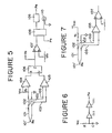
- FIG. 5 there is shown a detection circuit which is adapted to illuminate an indicator lamp and actuate an alarm upon detection of an instantaneous increase in resistance of a probe element 101 when its initially "closed circuit" sensing point 101' (in the normal or non-sensing state) is melted due to wear of the refractory wall.
- indicated at 102 are current lead wires, at 103 voltage lead wires, at 104 and 105 differential amplifiers, at 106, a divider, at 107 a voltage comparator, at 108 a flip-flop, at 109 a mono-stable multivibrator, and at 110 an indicator lamp.
- the voltage Vcc rises and a current i is supplied to the probe element 101 through R1.
- the voltage across the resistance R1 is amplified by the differential amplifier 104 with a gain Gi and supplied to the divider 106 as input X.
- the voltage Vx at the input X which is expressed by the following equation (1) is proportional to the amount of current flowing through the probe element 101.
- the voltage V2 is, after being amplified by the differential amplifier 105 with a gain Gv, supplied to the divider as input Y. Therefore, the voltage Vy at the input Y is expressed by the following equation (3).
- the divider 6 On the basis of the voltages at the input S, X and Y, the divider 6 operates in accordance with the following equation (4) to give an output voltage Vo.
- the output voltage Vo of the divider 106 is proportional to the resistance Rs of the sensing point 101'.
- the output Vo of the divider is fed to voltage comparator 107 for comparison with a predetermined reference voltage Vs which is determined by a variable resistor Vr1. If the output Vo of the divider 106 is smaller than the reference voltage Vs, that is to say, when the resistance Rs of the sensing point 101' is small, the output of the voltage comparator 107 is maintained at a high level.
- a reset pulse PR is fed to the flip-flop 108 as soon as the power switch is turned on as will be described hereinafter, thereby resetting flip-flop 108.
- FIG 6 which shows an example of a reset pulse generator circuit
- the voltage Vcc rises upon turning on the power switch and capacitor C starts charging through resistance R, so that the voltage across capacitor C rises with a delay time constant RC.
- the output PR of two Schmit trigger inverters 111 is maintained at a low level.
- the output PR turns to high level.
- flip-flop 108 is reset by the low level signal which appears at the output terminal of the Schmit trigger inverters 111.
- the indicator lamp 110 which is lit and the mono-stable multivibrator 109 which is operated by the output signal of flip-flop 108 are in the "off" state when the power switch is turned on.
- the sensing point 101' of the probe element 101 which is embedded in the refractory wall is exposed due to wear of the refractory wall, the initially shortcircuited sensing point 101' is melted away and is in an "open circuit” state but it is not completely in an “open circuit” state due to slag deposition and thus exhibits a certain limited resistance. Consequently, current flow through the probe element 101 is reduced, increasing the voltage across the sensing point 101'.
- FIG. 7 is a circuit diagram incorporating a conventional voltage detection circuit, in which the supply voltage differential amplifier 104 and divider 106 of Figure 5 are omitted, applying to comparator 107 only the current which is received through lead wires 103 after amplification to detect variations in voltage of the sensing point 101'.
- the input voltage Vvi of the differential amplifier 105 is expressed by the following equation (5).
- the output sensitivity against variations in resistance of the sensing point 101' can be obtained by differentiating equation (6) with the resistance Rs, as expressed by the following equation (7).
- the detection sensitivity in the conventional overlap voltage method varies with the supply voltage Vcc.
- the sensitivity is lowered markedly as the resistance of the sensing point Rs is increased. Consequently, it becomes necessary to set the resistances at predetermined values which sacrifices the possibility of interchanging the probe element.
- the detection circuit of the present invention is arranged to delete the influence of the supply voltage by the arithmetic operation which is performed by the divider 106 on the basis of the X- and Y-inputs. Therefore, fluctuations in the supply voltage do not appear in the output of the divider 106.
- equation (8) which expresses the output sensitivity relative to the resistance Rs of the sensing point, differentiating equations (4) and (6) with the resistance Rs, the output sensitivity is influenced only by the resistance R1 which is in the power supply line and not by the resistance Rs in any way whatsoever.
- the detection circuit of the invention is applicable to various kinds of probe elements and constantly ensures a high detection sensitivity irrespective of changes in resistance of the probe element.
- the detection circuit of Figure 5 operates in the manner as described below.
- the sensing point 101' When the sensing point 101' is of the normally "shortcircuited" type, it has a small resistance Rs and the output Vo of the divider 106 is maintained at a substantially constant small value. However, if the sensing point 101' is melted by wear of the refractory wall, its resistance Rs is increased and accordingly the output Vo of the divider 106 is also increased. Therefore, its relation to the constant reference voltage Vs is opposite to that before so that instead of increasing the output of comparator 107 it decreases the output of the comparator 107 to a low level. As a result, the flip-flop 108 which is set by the inverted signal produces an inverted output so that the indicator lamp is illuminated while actuating the mono-stable multivibrator 109 to produce a single low pulse PB.
- the output of the voltage comparator 107 is at a high level substantially the same as in the original shortcircuited state (before the sensing point 101' melts) but the indicator lamp 110 remains on since the output of flip-flop 108 is not inverted until it receives a reset signal PR.
- the detection circuit of the present invention operates to detect only the variation in resistance Rs which takes place in the initial stage of the disconnection by melting of the sensing point 101', and thereafter the indicator lamp 110 is kept on even if there are variations in the resistance of the sensing point due to deposition of molten steel or the like. Consequently, the wear of a refractory wall at a particular position where a probe element is embedded is known from the illuminated indicator lamp.
- Progressive wear of a refractory wall can be monitored by providing a plurality of the probe element and detection circuit of Figure 5, embedding the probe elements so that their sensing points are in different positions across the width of the refractory wall and arranging the corresponding indicator lamps in the same order. If a plurality of detection circuits are connected to a wired OR circuit as shown in Figure 8, an alarm is actuated when the indicator lamp of each circuit is illuminated. More specifically, in the circuit arrangement of Figure 8, the single low pulse output PB of each channel is connected to a wired OR circuit so that a flip-flop 112 is set to actuate an alarm 114 whenever any one of channels (1) to (n) produces a single low pulse output.
- the flip-flop 112 is reset by an output PR of a reset circuit as shown in Figure 6 upon connection to the power source, so that the alarm 114 is not actuated until the output PB is fed to the flip-flop 112.
- the flip-flop 112 is reset by depressing a switch 113.
- the flip-flop 112 Upon receipt of the next output PB, the flip-flop 112 is reset to actuate the alarm 114, and these operations are repeated to actuate the alarm 114 simultaneously with illumination of the respective indicator lamps 110.
- Figure 11 illustrates a detection circuit which uses a stabilized constant current power source 116 for a probe element 101.
- the current supply to the probe element 101 is constant, there is no need to take into account the fluctuations in the supply current, that is to say, no need to provide a divider as shown at 106 of Figure 5, and only a variation of the resistance of the sensing point 101' is amplified and applied to one input terminal of the voltage comparator 107.
- the detection circuit operates in the same manner as in Figure 5 to indicate the disconnection by melting of the sensing point 101'.
- the stabilized constant current power source 116 has an output current
- the output Vvi of the differential amplifier 105 is expressed by the following equation (9)
- the output Vvi of the differential amplifier 105 is also proportional to the resistance Rs of the sensing point 101', and the output sensitivity relative to variations in the resistance Rs of the sensing point (which is obtained by differentiating the output with the resistance Rs) is constant, as expressed by the following equation (10).
- the degree of wear of a refractory wall can be detected with the same high accuracy as the detection circuit shown in Figure 5.
- a number of circuits of Figure 11 may also be connected to a wired OR circuit as described hereinbefore with reference to Figure 8, thereby to monitor the progressive wear of a refractory wall, and producing an alarm when each stage of wear is reached. Where an open contact type probe element is used, the circuit arrangement is altered as shown in Figures 9 and 10.
- the present invention employs a method of detecting a voltage drop by a voltmeter-ammeter system.
- the value of resistance is obtained from a ratio of a current flowing into a resistance to a voltage across a component so that it is sufficient to measure the voltage alone if the current is constant or alternatively one may measure the current flow while maintaining the voltage constant. Either way, it is possible to secure a sufficiently high precision by a relatively simple circuit arrangement.
- the resistance charges to over 300 ohms at the time of disconnection by melting and a resistance smaller than 100 ohms when the probe wires are shortcircuited by contact with molten steel.
- the detection circuit arrangement according to the present invention can detect even a slight variation in the resistance of the sensing point of a probe element, which is reflected by a variation in voltage, reliably with a high sensitivity, allowing one to monitor accurately the progressive wear of a refractory wall.
- Figure 12 illustrates, as an example of the molten metal processing apparatus to which the present invention is applicable, a converter which is provided with a bottom blowing gas nozzle at the bottom thereof.
- Figures 13 to 15 show the nozzle portion of the converter in an enlarged section.
- the top blowing oxygen processes which have thus far been most popular in the art of refining molten metal A in a converter 201 may now be replaced by a bottom blown oxygen process which blows in oxygen through a gas nozzle 202 provided at the bottom of the converter or most probably by a top and bottom blown process which additionally blows in oxygen through a lance 203.
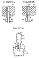
- the gas blowing nozzle 202 there are known in the art a single-tube nozzle as shown in Figure 13 and a double-tube nozzle as shown in Figure 14.
- an annular gas blowing nozzle the inner tube of which is packed with a refractory material 204 so that the gas is blown through the outer tube alone (as shown particularly in Figure 15) gives better results.
- No matter which nozzle is used it is necessary to blow in a gas under a pressure greater than that of the molten metal A so that the molten metal A in the vicinity of the nozzle is vigorously agitated, causing back- attacks against up-blows. Consequently, the refractory walls in the neighbourhood of the gas blowing nozzle wear considerably more quickly than other areas.
- FIG 16 shows an RH vacuum melter 205 with a riser pipe 206 and a downpipe 207 at the bottom thereof immersed in molten metal A in a ladle 208.
- An inert gas is blown in through a nozzle 202 which is provided on the riser pipe 206 to lift up the molten metal A into the RH vacuum melter 205 by means of the rising gas for treatment therein, the treated molten metal returning to the ladle 208 through the down pipe 207.
- the molten metal A is degassed and, if necessary, alloy elements are added by feeding through a hopper 209 at the top end of the melter to adjust the chemical composition.
- a hopper 209 at the top end of the melter to adjust the chemical composition.
- the probe assembly according to the present invention is particularly useful for accurately detecting from outside the degree of wear of the refractory wall around the gas blowing nozzle in these metal processing operations.
- a probe assembly 210 is embedded in a refractory wall in the vicinity of a gas blowing nozzle 202 across the width of the refractory wall.
- a probe assembly is embedded in the packed refractory material within the gas blowing nozzle as shown in Figure 19 (in which the dummy elements are not specifically illustrated).
- the dummy elements 4' and refractory filler material are eroded substantially at the same rates as the refractory material, and the wires 3a and 3b at the sensing point P are brought into contact with the molten metal from each successive probe element, producing a signal by the melting shortcircuiting of the sensing point P in the case of a normally "open circuit” probe element ( Figure 1) or in a melting disconnection in the case of a normally "closed circuit” probe element ( Figure 2).
- the detection circuit illuminates a corresponding indicator lamp to indicate exactly the current stage of progressive wear of the refractory wall in which the probe assembly is embedded.
- the dummy elements which are connected to the front ends of the respective probe elements serve to uniformalize the condition and speed of heat transfer to the heat sensing point of the individual probe elements, while preventing molten metal from attacking the probe assembly prematurely before wear of the refractory wall to thereby reduce detection errors to a minimum.
- the above-described wear detection probe assembly is embedded either in a refractory filler material at the centre of a gas blowing nozzle 202 or in a refractory wall portion in the vicinity of a gas blowing nozzle, as shown in Figures 17 to 19.
- the probe assembly is located too close to the nozzle 202, there is the possibility of reducing its detection sensitivity due to the cooling effect of the gas blown in. Therefore, it is preferred to embed the probe assembly at a distance of about 4-10 cm from a nozzle 202.
- the invention is illustrated more particularly by the following example.
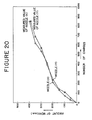
- a pair of nozzles (X, Y) were provided at the bottom of a top and bottom blown converter as shown in Figure 19, and a wear detection probe assembly was embedded in the refractory filler material packed in the inner tube of each nozzle.
- the probe assembly had eight normally "open-circuit" type probe elements with a spacing of 50 mm between the respective sensing points which were located in different positions along the length of a sheath enclosure as shown in Figure 1. After charging molten steel into the converter, oxygen was blown in from the top through a lance while Ar gas was blown in through the bottom nozzles at a flow rate of 0.02-0.10 N . m/min . per ton of steel.
- the experiment was interrupted at the 845th charge when the 8th probe element of the probe in the nozzle Y had not yet melted.
- the nozzles were extracted from the bottom of the converter and the thickness of the refractory wall was measured to confirm the extent of actual wear, which was 408 mm.
- the extent of wear detected by the probe was 400 mm with an error as small as 2% [(408-400)/ 400x100].
- the probe proved to be able to detect the wear with a high accuracy.
Landscapes
- Engineering & Computer Science (AREA)
- Chemical & Material Sciences (AREA)
- Manufacturing & Machinery (AREA)
- Materials Engineering (AREA)
- Metallurgy (AREA)
- Organic Chemistry (AREA)
- Mechanical Engineering (AREA)
- General Engineering & Computer Science (AREA)
- Measurement Of Length, Angles, Or The Like Using Electric Or Magnetic Means (AREA)
- Waste-Gas Treatment And Other Accessory Devices For Furnaces (AREA)
Description
- This invention relates to a probe and a system for detecting wear of a refractory wall by the use of the probe.
- The bodies of blast furnaces, converters and ladles which constitute containers for holding hot molten metal or for conducting vigorous metallurgical reactions at a high temperature as well as the bodies of soaking pits which internally maintain high temperatures over a long time period, generally have a lining of refractory material on the inner side of a frame or housing formed by a shell or the like. The refractory lining layer is repeatedly subjected to thermal and/or mechanical shocks, and as a result it is gradually embrittled. A worn-out refractory wall will easily break off unless a temporary or more permanent repair is made. Therefore, from the standpoint of safe operation, it is essential to keep the condition of wear of the refractory material (orthe degree of persistence) constantly under strict supervision.
- In this connection, the most popular method has been to estimate the condition of the refractory layer from the appearance or temperature of the outer shell, which provides an estimate which is not very accurate. Therefore, the present inventors proposed in their Laid-Open Japanese Utility Specification No. 55-105140 a temperature distribution sensor which is capable of detecting the condition of the inner refractory wall surface, with a relatively high accuracy when applied by the refractory wall wear monitoring method disclosed in Laid-Open Japanese Patent Specification No. 55-119114. However, this method which depends on arithmetic operations by a computer is difficult to apply readily to different kinds of refractory walls and thus lacks versatility. If a sensor which is embedded in a refractory wall is broken by wear of the refractory wall, it produces an abnormal output signal which can be used for the detection of the critical condition of the refractory wall in a simple method of wear detection. However, as the above mentioned thermal sensor utilizes a sheath type thermocouple or sheath type resistance theremo- meter, its output signal is essentially a temperature signal. Therefore, it is not always easy to distinguish a signal variation due to a sudden change in the furnace temperature from a variation due to the breakage of the sensor. Consequently, it is possible to make an error so that there remains a problem with regard to the reliability of operation.
- Further, Japanese Utility Model Publication No. 53-8370 discloses a sheath type multi-point temperature probe having a plurality of sheath type thermocouples or a plurality of sheath type resistance thermometers formed by connecting wires of predetermined lengths to the front ends of heat sensing points and which are accommodated in a protective tube with the respective heat sensing points located at different positions along the length of the protective tube, the outer diameter of the protective tube being reduced subsequently to form an integral probe assembly. This probe assembly differs from the above-mentioned sensor in that it uses no insulating material between the sheath and protective tube and the material which constitutes the thermocouples or resistance thermometers is not used at the heat sensing points.
- Under these circumstances, the present inventors furthered their studies in the search for simpler and more reliable means which is capable of accurately detecting the amount of wear of refractory walls, and as a result succeeded in developing a novel probe which will be described hereinafter, and a detection circuit which is suitable for use in combination with the probe. This detection circuit differs from ordinary electrical disconnection detecting means which are generally arranged to detect an abnormal state by means of a variation in the resistance across a detecting element in its shortcircuited and its disconnected states. For example, means for detecting an abnormal state of a thermocouple are disclosed in Laid-Open Japanese Patent Application Nos. 55-60828 and 55-117982, Japanese Utility Model Publication No. 55-11456 and Laid Open Japanese Utility Model Application No. 54-102167. However, if these known detecting means are applied to a molten metal processing system such as a blast furnace or converter, the abnormal state is often overlooked because the variation in resistance is very small even in the event of a wire breakage, due to slag deposition at the end of the detecting element, or because the molten pig iron or molten steel which contacts the end of the detecting element creates a shortcircuit despite the wire breakage.
- In view of these problems, the present inventors endeavoured to develop a detection circuit which can detect even an instantaneous variation in resistance which may take place by occurrence of an abnormal state, and succeeding in obtaining a novel detection circuit of satisfactory performance characteristics.
- In this connection, a mention may be made of DE-OS 2,005,399 disclosing a device for monitoring wear of a refractory layer, which requires many holes to be bored in the refractory wall itself and it requires detection wires to be laid in the refractory bricks before building the wall, and there is also the problem of reliability arising from the limited number of circuit systems.
- The present invention contemplates to eliminate the above-mentioned difficulties and problems of the prior art, and has as its primary object the provision of a probe which can detect the degree of wear of a refractory wall in a simple and accurate manner.
- It is another object of a preferred arrangement of the present invention to provide a system for monitoring the wear of a refractory wall, which employs a novel refractory wall wear detection circuit in combination with the probe.
- According to one aspect of the present invention there is provided a probe for detecting the degree of wear of a refractory wall, comprising a plurality of sheathed probe elements each consisting of a parallel pair of high melting point wires, (3a, 3b) the front ends of said wires forming a normally closed circuit or normally open circuit sensing point, and the remainder of the wires being insulated from each other, said probe being characterised by a sheath enclosure accommodating said probe elements such that the sensing points of the respective probe elements are located at different positions along the length of said sheath enclosure, said sheath enclosure holding said probe elements in parallel relation and out of contact with each other, and dummy elements formed of a material similar to said probe elements and extending from the front ends of the shorter probe elements.
- According to another aspect of the invention, there is provided a refractory wall wear detecting apparatus comprising a probe to be embedded in a refractory wall and a detecting circuit characterised by a probe of the type set out in the preceding paragraph and a power source for supplying current to said probe elements; a circuit for detecting the amount of current flowing to said probe elements; a circuit for detecting the voltage across said probe elements; a divider adapted to produce an output voltage indicative of the ratio of the detected amount of current to said voltage, across said probe elements, a comparator adapted to compare said output voltage of said divider with a predetermined reference voltage; and an indicator circuit operated by the output signal of said comparator.
- According to another aspect of the invention there is provided a refractory wall wear detection circuit for detecting the degree of wear of a refractory wall by means of a probe of the type set out in the second previous paragraph embedded therein, said circuit being characterised by a stabilised constant current power source for supplying constant current to said probe element; a circuit for detecting the voltage across said probe element; a comparator adapted to compare said voltage across the probe with a predetermined reference voltage; and an indicator circuit operated by an output signal from said comparator.
- The invention also provides a molten metal processing apparatus having a gas blowing nozzle at the bottom or in the wall of a furnace characterised by a refractory wall wear detection probe embedded in a refractory wall in the vicinity of said gas blowing nozzle and having a plurality of sheathed probe elements each consisting of a pair of parallelly disposed high melting point wires insulated from each other except at least at the front end of said wires forming a sensing point to detect a variation in electric current caused by disconnection by melting thereof, a sheath enclosure accommodating said probe elements such that the sensing points of the respective probe elements are located at different positions along the length of said sheath enclosure, said sheath enclosure holding said probe elements in parallel relation and out of contact with each other, and a number of dummy elements formed of a material similar to said probe elements and extending from the front ends of the shorter probe elements.
- The above and other objects, features and advantages of the present invention will become apparent from the following description and appended claims, read in conjunction with the accompanying drawings which show by way of example preferred embodiments of the present invention.
- In the accompanying drawings:
- Figures 1 and 2 are diagrammatic views of two different probes showing how probes of the type according to the invention operate;
- Figure 3 is a partly cutaway side view of a probe element according to the invention;
- Figure 4 is a partly cutaway perspective view of a probe according to the invention;
- Figure 5 is a diagram of a detection circuit for use with a probe according to the present invention;
- Figure 6 is a diagram of a flip-flop reset circuit;
- Figure 7 is a circuit diagram showing a conventional disconnection detecting circuit;
- Figure 8 is a circuit diagram exemplifying the detection circuit for use with a probe of the invention as connected to a wired OR circuit;
- Figures 9 and 10 are fragmentary circuit diagrams showing modifications using a normally open detecting element;
- Figure 11 is a diagram of another embodiment of a detection circuit;
- Figure 12 is a diagrammatic vertical section of a top and bottom blown converter;
- Figures 13 to 15 are fragmentary diagrammatic sections showing examples of a gas blowing nozzle;
- Figure 16 is a diagrammatic view of a RH vacuum melter;
- Figures 17 to 19 are fragmentary sectional views of a gas blowing nozzle portion including probes of the invention; and
- Figure 20 is a graphic illustration of experimental data.
- A probe of the present invention comprises a pair of high melting point wires which are received in a sheathing in parallel relation with each other, the wires forming either a normally closed or a normally open sensing point at their tip ends. Another feature of the probe resides in the use of a plurality of these sheathed probe elements of different lengths which are arranged in a single sheath enclosure such that the sensing points of the respective probe elements are located at different positions along the length of the outer sheath enclosure. There are also provided, for each probe element which does not extend to the end of the probe itself, dummy elements comprising a material similar to the probe elements themselves and extending from the tip ends of the respective probe elements towards the end of the probe itself so that, in each case, the combined lengths of the probe elements and their respective dummy elements is the same.
- Figure 1 diagrammatically illustrates a probe (in which the dummy elements are omitted for reasons of clarity) which illustrates the mode of operation of one type of probe of the invention, with a non-contacting or normally "open circuit" sensing point P, which illustrates the operating principles of the invention. Figure 2 (in which the dummy elements are also omitted) illustrates a probe element similar to the probe element of Figure 1 but having a contacting or normally "closed circuit" sensing point P. Referring first to Figure 1, a pair of high
melting point wires molten metal 2. Consequently, the sensing point P undergoes no change and no electric current flows between thewires wires wires molten metal 2. Therefore, when this happens there is immediate conduction of current if a potential is applied to the two wires, and it can be deduced from the generation or increase of current between thewires molten metal 2 as shown at B of Figure 1, the shortcircuiting of the sensing point P' takes place when the refractory wall 1 is worn down to the position indicated by broken line b. It follows that, if a number of probe elements are embedded with their respective sensing points at different positions across the width of the refractory wall 1, the melting shortcircuiting occurs in successive probe elements depending on the position of the positions of their sensing points, making it possible to know exactly the extent of wear of the refractory wall 1. - The normally "closed circuit" probe of Figure 2 operates essentially on the same principles as in the "open circuit" probe of Figure 1. More particularly, when the refractory wall 1 is in a sound state as shown at A of Figure 2, current flows through the sensing point P. However, the sensing point P is affected by the heat of the approaching
molten metal 2 and is finally melted, breaking the current flow through the sensing point P. Therefore, it can be assumed that the wear of the refractory wall 1 has proceeded to the stage of A'should the value of current flow across thewires - In the case of Figure 2, therefore, it is possible to determine that the wear of the refractory wall has proceeded to the stage A' of A" by detecting a current drop or zero current flow between the conducting stages A and A", which current drop is of an extremely short time period (or is instantaneous in most cases). The broken lines B and b indicate the same conditions as in Figure 1.
- The foregoing description assumes that there is
molten metal 2 within the refractory wall 1. However, where thewires wires wires wires wires wires - The construction of a probe according to the present invention will now be described in greater detail. Referring to Figure 3 which shows a partly cutaway side view of a probe element of the invention, a parallel pair of
wires wires 
- The
wires material 5 like magnesia which also suppresses heat transfer in the longitudinal direction of the probe element. The pairedwires wires - Figure 4 shows a probe assembly having a plurality of sheathed probe elements which are mounted in parallel relation with each other in a
sheath enclosure 8 of the same material as thesheathing 4 of each probe element. The sheath-ings 4 of the respective probe elements are insulated from each other by a suitable refractory material like magnesia which fills thesheath enclosure 8 although the filler refractory material is not shown in Figure 4 for the convenience of illustration. The probe assembly is embedded in a refractory wall of a furnace with its sensing end, (the upper right-hand end in Figure 4) towards the inner surface of the refractory wall. Accordingly, the front ends of the respective probe elements are disposed towards the sensing end of the probe assembly but the sensing points P of individual probe elements are positioned at different points along the length of the probe assembly as shown in Figure 4. Although the sensing points P of different probe elements are positioned at regular intervals along the length of the probe assembly in the particular example shown, they may be located at arbitrary positions or, of course, at random positions if desired. However, the sensing points P are preferred to be arranged in a predetermined pattern because the positions of the respective sensing points P in the refractory wall in which the probe assembly is embedded should be exactly known. Dummy elements 4' which are made of the same material as theprobe elements 4 extend between the front end of thesheath enclosure 8 and the sensing points P of theshorter probe elements 4, the dummy elements 4' being provided to create uniform measuring conditions along the length of the respective probe elements. Thedummy elements 4 may or may not contain wires but, if they do, the wires are not connected to thewires probe elements 4. In Figure 4, thereference numeral 7 denotes a connection of aprobe element 4 and a respective dummy element 4', whichconnection 7 can be dispensed with in the case where the sheathed probe elements are formed so as to be the same length and each consists of wired portions extending to sensing points at different positions and complementary dummy portions. In this instance, there is a possibility of the sensing point malfunctioning because of furnace heat which tends to propagate toward the sensing point through the sheathing when the dummy portion is exposed to the furnace due to wear of the refractory wall. In order to suppress such thermal propogation, it is necessary to increase the density of the insulating filler material in thesheathing 4. - In the embodiment shown in Figure 4, one of the six probe elements extends through the entire length of the
sheath enclosure 8 with its sensing point P located at the front end of thesheath enclosure 8 and does not have an associated dummy element, so that the sensing point P is disposed at a position close to the inner surface of the refractory wall. If desired, however, the probe elements may be accommodated in a sheath enclosure of a greater length than the probe elements so that dummy elements will extend between all of the sensing points P and the outer end of the probe assembly. - Since the degree of wear of the refractory wall is detected by way of an electric signal which is produced by disconnection or connection of the
wires sheathing 4 andsheath enclosure 8 should be suppressed to the maximum degree. For this purpose, it is necessary to increase the density of the refractory filler material as mentioned hereinbefore to reduce the quantity of residual air in the filler material. One method which can serve for this purpose is to subject the filled sheath to a drawing operation (i.e. reduction of diameter) to squeeze out the residual air. - The probe assembly of the above-described construction indicates the degree of wear simply by electric on-off signals or abrupt changes in electrical resistance or current, without relying on temperature signals or complicated calculations and analysis by a computer, so that the detection of wear of the refractory wall is greatly facilitated. The probe assembly can be readily used on various molten metal containers or on thermal processing systems and can indicate the progressive wear of a refractory wall with high precision.
- When the above-described probe assembly is used for detecting wear of a refractory wall, the probe assembly is connected to a detection circuit which comprises a power source for supplying current to a probe element, a circuit for detecting the amount of current flowing to the probe element, a divider for calculating the ratio of the detected amount of current to a voltage across the ends of the probe element, a comparator for comparing the output voltage of the divider with a predetermined reference voltage, and an indicator circuit operated by the output voltage of the comparator. In a case where the power source is a stabilized constant-current power source, the detection circuit can omit the current detecting circuit and divider, and can be operated simply by providing a circuit for detecting the voltage across the sensing element, a comparator for comparing the detected voltage with a predetermined reference voltage, and an indicator circuit operated by the output voltage of the comparator.
- The operation and resulting effects of preferred arrangements of the present invention are hereafter described using circuit diagrams, which however are not intended to limit the present invention in any way whatsoever, and it is to be understood that the present invention includes all the modifications and alterations or additions which may be made to the particular circuit arrangements shown by those skilled in the art in consideration of the foregoing and succeeding descriptions.
- Referring to Figure 5, there is shown a detection circuit which is adapted to illuminate an indicator lamp and actuate an alarm upon detection of an instantaneous increase in resistance of a
probe element 101 when its initially "closed circuit" sensing point 101' (in the normal or non-sensing state) is melted due to wear of the refractory wall. In this figure, indicated at 102 are current lead wires, at 103 voltage lead wires, at 104 and 105 differential amplifiers, at 106, a divider, at 107 a voltage comparator, at 108 a flip-flop, at 109 a mono-stable multivibrator, and at 110 an indicator lamp. Upon turning on a power source, the voltage Vcc rises and a current i is supplied to theprobe element 101 through R1. The voltage across the resistance R1 is amplified by thedifferential amplifier 104 with a gain Gi and supplied to thedivider 106 as input X. The voltage Vx at the input X which is expressed by the following equation (1) is proportional to the amount of current flowing through theprobe element 101.
- If the resistance of sensing point 101' is represented by Rs, the voltage V2 across the
probe element 101 is expressed by the following equation (2).
- The voltage V2 is, after being amplified by the
differential amplifier 105 with a gain Gv, supplied to the divider as input Y. Therefore, the voltage Vy at the input Y is expressed by the following equation (3).
- On the basis of the voltages at the input S, X and Y, the divider 6 operates in accordance with the following equation (4) to give an output voltage Vo.

- As will be understood therefrom, the output voltage Vo of the
divider 106 is proportional to the resistance Rs of the sensing point 101'. - The output Vo of the divider is fed to
voltage comparator 107 for comparison with a predetermined reference voltage Vs which is determined by a variable resistor Vr1. If the output Vo of thedivider 106 is smaller than the reference voltage Vs, that is to say, when the resistance Rs of the sensing point 101' is small, the output of thevoltage comparator 107 is maintained at a high level. - Since it is unpredictable whether the output of the flip-
flop 108 is at high or low level upon connecting the power supply, a reset pulse PR is fed to the flip-flop 108 as soon as the power switch is turned on as will be described hereinafter, thereby resetting flip-flop 108. Referring to Figure 6 which shows an example of a reset pulse generator circuit, the voltage Vcc rises upon turning on the power switch and capacitor C starts charging through resistance R, so that the voltage across capacitor C rises with a delay time constant RC. In this instance, as the voltage across capacitor C remains low immediately after the rise of the supply voltage Vcc, the output PR of two Schmit trigger inverters 111 is maintained at a low level. After a lapse of time corresponding to the time constant RC, the output PR turns to high level. Thus, flip-flop 108 is reset by the low level signal which appears at the output terminal of the Schmit trigger inverters 111. - The
indicator lamp 110 which is lit and the mono-stable multivibrator 109 which is operated by the output signal of flip-flop 108 are in the "off" state when the power switch is turned on. - If the sensing point 101' of the
probe element 101 which is embedded in the refractory wall is exposed due to wear of the refractory wall, the initially shortcircuited sensing point 101' is melted away and is in an "open circuit" state but it is not completely in an "open circuit" state due to slag deposition and thus exhibits a certain limited resistance. Consequently, current flow through theprobe element 101 is reduced, increasing the voltage across the sensing point 101'. - It is difficult to detect accurately a slight variation in resistance by conventional disconnection detecting circuits which are arranged to detect only a variation in overlapped voltage. Besides, a serious problem is encountered in the conventional overlapping detection method in that the detection sensitivity is considerably lowered by an increase in resistance of the sensing point 101', coupled with a problem that the output is markedly varied by fluctuations in the supply voltage Vcc as will be explained hereafter. Figure 7 is a circuit diagram incorporating a conventional voltage detection circuit, in which the supply
voltage differential amplifier 104 anddivider 106 of Figure 5 are omitted, applying tocomparator 107 only the current which is received throughlead wires 103 after amplification to detect variations in voltage of the sensing point 101'. With this circuit arrangement, the input voltage Vvi of thedifferential amplifier 105 is expressed by the following equation (5).
- If it is amplified by the
differential amplifier 5 with a gain Gv, its output Vvo is expressed by the following equation (6).
- In this instance, the output sensitivity against variations in resistance of the sensing point 101' can be obtained by differentiating equation (6) with the resistance Rs, as expressed by the following equation (7).

- As is clear from equation (7), the detection sensitivity in the conventional overlap voltage method varies with the supply voltage Vcc. The sensitivity is lowered markedly as the resistance of the sensing point Rs is increased. Consequently, it becomes necessary to set the resistances at predetermined values which sacrifices the possibility of interchanging the probe element.
- In contrast, as is obvious from equation (4), the detection circuit of the present invention, which is shown in Figure 5, is arranged to delete the influence of the supply voltage by the arithmetic operation which is performed by the
divider 106 on the basis of the X- and Y-inputs. Therefore, fluctuations in the supply voltage do not appear in the output of thedivider 106. Besides, as is clear from the following equation (8) which expresses the output sensitivity relative to the resistance Rs of the sensing point, differentiating equations (4) and (6) with the resistance Rs,
- If the sensing point 101' of the
probe element 101 is melted, the detection circuit of Figure 5 operates in the manner as described below. - When the sensing point 101' is of the normally "shortcircuited" type, it has a small resistance Rs and the output Vo of the
divider 106 is maintained at a substantially constant small value. However, if the sensing point 101' is melted by wear of the refractory wall, its resistance Rs is increased and accordingly the output Vo of thedivider 106 is also increased. Therefore, its relation to the constant reference voltage Vs is opposite to that before so that instead of increasing the output ofcomparator 107 it decreases the output of thecomparator 107 to a low level. As a result, the flip-flop 108 which is set by the inverted signal produces an inverted output so that the indicator lamp is illuminated while actuating the mono-stable multivibrator 109 to produce a single low pulse PB. - If molten steel deposits on the melted sensing point 101', the output of the
voltage comparator 107 is at a high level substantially the same as in the original shortcircuited state (before the sensing point 101' melts) but theindicator lamp 110 remains on since the output of flip-flop 108 is not inverted until it receives a reset signal PR. - In this manner, the detection circuit of the present invention operates to detect only the variation in resistance Rs which takes place in the initial stage of the disconnection by melting of the sensing point 101', and thereafter the
indicator lamp 110 is kept on even if there are variations in the resistance of the sensing point due to deposition of molten steel or the like. Consequently, the wear of a refractory wall at a particular position where a probe element is embedded is known from the illuminated indicator lamp. - Progressive wear of a refractory wall can be monitored by providing a plurality of the probe element and detection circuit of Figure 5, embedding the probe elements so that their sensing points are in different positions across the width of the refractory wall and arranging the corresponding indicator lamps in the same order. If a plurality of detection circuits are connected to a wired OR circuit as shown in Figure 8, an alarm is actuated when the indicator lamp of each circuit is illuminated. More specifically, in the circuit arrangement of Figure 8, the single low pulse output PB of each channel is connected to a wired OR circuit so that a flip-
flop 112 is set to actuate analarm 114 whenever any one of channels (1) to (n) produces a single low pulse output. In this instance, the flip-flop 112 is reset by an output PR of a reset circuit as shown in Figure 6 upon connection to the power source, so that thealarm 114 is not actuated until the output PB is fed to the flip-flop 112. In order to stop thealarm 114, the flip-flop 112 is reset by depressing aswitch 113. Upon receipt of the next output PB, the flip-flop 112 is reset to actuate thealarm 114, and these operations are repeated to actuate thealarm 114 simultaneously with illumination of therespective indicator lamps 110. - Although the illumination of a lamp or indicator lamps is the simplest method of displaying the degree of wear, one may use an LED, a meter or a CRT display. Where an "open-circuit" type probe element (which is initially in the "open-circuit" state and is shortcircuited by contact with molten steel when it melts) is employed instead of the above-described "closed circuit" type probe element, the detection circuit of Figure 5 is altered in the following manner. Since the output of the
voltage comparator 107 is inverted when the "closed circuit" type probe element is replaced by an "open circuit" type, it is necessary either to reverse the connection to the input terminals of thecomparator 107 as shown in Figure 9 or to insert aninverter 115 between thecomparator 107 and flip-flop 108 as shown in Figure 10. - The description is now directed to another embodiment of detection circuit according to the present invention, which employs a stabilized constant current power source. More particularly, Figure 11 illustrates a detection circuit which uses a stabilized constant
current power source 116 for aprobe element 101. In this case, since the current supply to theprobe element 101 is constant, there is no need to take into account the fluctuations in the supply current, that is to say, no need to provide a divider as shown at 106 of Figure 5, and only a variation of the resistance of the sensing point 101' is amplified and applied to one input terminal of thevoltage comparator 107. In other respects, the detection circuit operates in the same manner as in Figure 5 to indicate the disconnection by melting of the sensing point 101'. In this embodiment, if the stabilized constantcurrent power source 116 has an output current the output Vvi of thedifferential amplifier 105 is expressed by the following equation (9)
- Thus, the output Vvi of the
differential amplifier 105 is also proportional to the resistance Rs of the sensing point 101', and the output sensitivity relative to variations in the resistance Rs of the sensing point (which is obtained by differentiating the output with the resistance Rs) is constant, as expressed by the following equation (10).
- Thus, the degree of wear of a refractory wall can be detected with the same high accuracy as the detection circuit shown in Figure 5. A number of circuits of Figure 11 may also be connected to a wired OR circuit as described hereinbefore with reference to Figure 8, thereby to monitor the progressive wear of a refractory wall, and producing an alarm when each stage of wear is reached. Where an open contact type probe element is used, the circuit arrangement is altered as shown in Figures 9 and 10.
- In detecting a variation in resistance of the sensing point, the present invention employs a method of detecting a voltage drop by a voltmeter-ammeter system. According to this method, the value of resistance is obtained from a ratio of a current flowing into a resistance to a voltage across a component so that it is sufficient to measure the voltage alone if the current is constant or alternatively one may measure the current flow while maintaining the voltage constant. Either way, it is possible to secure a sufficiently high precision by a relatively simple circuit arrangement. For example, in a case where the detection system incorporates a probe element with a resistance (before melting) of about 10-100 ohms, the resistance charges to over 300 ohms at the time of disconnection by melting and a resistance smaller than 100 ohms when the probe wires are shortcircuited by contact with molten steel.
- As will be understood from the foregoing description, the detection circuit arrangement according to the present invention can detect even a slight variation in the resistance of the sensing point of a probe element, which is reflected by a variation in voltage, reliably with a high sensitivity, allowing one to monitor accurately the progressive wear of a refractory wall.
- Figure 12 illustrates, as an example of the molten metal processing apparatus to which the present invention is applicable, a converter which is provided with a bottom blowing gas nozzle at the bottom thereof. Figures 13 to 15 show the nozzle portion of the converter in an enlarged section. The top blowing oxygen processes which have thus far been most popular in the art of refining molten metal A in a
converter 201 may now be replaced by a bottom blown oxygen process which blows in oxygen through agas nozzle 202 provided at the bottom of the converter or most probably by a top and bottom blown process which additionally blows in oxygen through alance 203. With regard to thegas blowing nozzle 202, there are known in the art a single-tube nozzle as shown in Figure 13 and a double-tube nozzle as shown in Figure 14. As far as we know, an annular gas blowing nozzle, the inner tube of which is packed with arefractory material 204 so that the gas is blown through the outer tube alone (as shown particularly in Figure 15), gives better results. No matter which nozzle is used, it is necessary to blow in a gas under a pressure greater than that of the molten metal A so that the molten metal A in the vicinity of the nozzle is vigorously agitated, causing back- attacks against up-blows. Consequently, the refractory walls in the neighbourhood of the gas blowing nozzle wear considerably more quickly than other areas. Especially in a case where oxygen or similar gas is blown in through thenozzle 202, the metallurgical reactions take place most vigorously in an area around thenozzle 202, accelerating the wear of the refractory wall in that area. Figure 16 shows anRH vacuum melter 205 with ariser pipe 206 and adownpipe 207 at the bottom thereof immersed in molten metal A in aladle 208. An inert gas is blown in through anozzle 202 which is provided on theriser pipe 206 to lift up the molten metal A into theRH vacuum melter 205 by means of the rising gas for treatment therein, the treated molten metal returning to theladle 208 through thedown pipe 207. During the cyclic operation, the molten metal A is degassed and, if necessary, alloy elements are added by feeding through ahopper 209 at the top end of the melter to adjust the chemical composition. In this case, an area around thegas blowing nozzle 202, especially an area immediately above thenozzle 202, also is subject to accelerated wear. The probe assembly according to the present invention is particularly useful for accurately detecting from outside the degree of wear of the refractory wall around the gas blowing nozzle in these metal processing operations. - As illustrated particularly in Figures 17 and 18 (in which the dummy elements are not specifically illustrated), a
probe assembly 210 is embedded in a refractory wall in the vicinity of agas blowing nozzle 202 across the width of the refractory wall. Alternatively, a probe assembly is embedded in the packed refractory material within the gas blowing nozzle as shown in Figure 19 (in which the dummy elements are not specifically illustrated). The dummy elements 4' and refractory filler material are eroded substantially at the same rates as the refractory material, and thewires - The above-described wear detection probe assembly is embedded either in a refractory filler material at the centre of a
gas blowing nozzle 202 or in a refractory wall portion in the vicinity of a gas blowing nozzle, as shown in Figures 17 to 19. However, if the probe assembly is located too close to thenozzle 202, there is the possibility of reducing its detection sensitivity due to the cooling effect of the gas blown in. Therefore, it is preferred to embed the probe assembly at a distance of about 4-10 cm from anozzle 202. - Thus, according to the present invention, it becomes possible to detect exactly from outside the degree of wear of a refractory wall portion in the neighbourhood of a gas blowing nozzle where erosion takes place to a maximum degree in a molten metal processing system. Consequently, a temporary or more permanent repair can be made in time to prevent leakage of molten metal or other accidents and to guarantee safe operations.
- The invention is illustrated more particularly by the following example.
- A pair of nozzles (X, Y) were provided at the bottom of a top and bottom blown converter as shown in Figure 19, and a wear detection probe assembly was embedded in the refractory filler material packed in the inner tube of each nozzle. The probe assembly had eight normally "open-circuit" type probe elements with a spacing of 50 mm between the respective sensing points which were located in different positions along the length of a sheath enclosure as shown in Figure 1. After charging molten steel into the converter, oxygen was blown in from the top through a lance while Ar gas was blown in through the bottom nozzles at a flow rate of 0.02-0.10 N . m/min . per ton of steel. The same operation was repeated to refine 845 charges of molten steel, while checking the wear of the refractory wall in the vicinity of the gas blowing nozzles by the probe assemblies. The progressive wear of the refractory wall detected by the respective probes are shown in Figure 20.
- The experiment was interrupted at the 845th charge when the 8th probe element of the probe in the nozzle Y had not yet melted. The nozzles were extracted from the bottom of the converter and the thickness of the refractory wall was measured to confirm the extent of actual wear, which was 408 mm. As is clearfrom Figure 20, the extent of wear detected by the probe was 400 mm with an error as small as 2% [(408-400)/ 400x100]. Thus, the probe proved to be able to detect the wear with a high accuracy.
Claims (4)
Applications Claiming Priority (6)
| Application Number | Priority Date | Filing Date | Title |
|---|---|---|---|
| JP29330/81 | 1981-03-02 | ||
| JP1981029330U JPS5930399Y2 (en) | 1981-03-02 | 1981-03-02 | Refractory wall erosion detection sensor |
| JP32721/81 | 1981-03-06 | ||
| JP3272181A JPS57148181A (en) | 1981-03-06 | 1981-03-06 | Errosion level detector for refractory wall |
| JP3473881A JPS57149436A (en) | 1981-03-11 | 1981-03-11 | Treating device for molten metal |
| JP34738/81 | 1981-03-11 |
Publications (2)
| Publication Number | Publication Date |
|---|---|
| EP0060069A1 EP0060069A1 (en) | 1982-09-15 |
| EP0060069B1 true EP0060069B1 (en) | 1985-08-28 |
Family
ID=27286520
Family Applications (1)
| Application Number | Title | Priority Date | Filing Date |
|---|---|---|---|
| EP82301045A Expired EP0060069B1 (en) | 1981-03-02 | 1982-03-02 | A probe and a system for detecting wear of refractory wall |
Country Status (5)
| Country | Link |
|---|---|
| US (1) | US4442706A (en) |
| EP (1) | EP0060069B1 (en) |
| AU (1) | AU531814B2 (en) |
| CA (1) | CA1197289A (en) |
| DE (1) | DE3265712D1 (en) |
Families Citing this family (23)
| Publication number | Priority date | Publication date | Assignee | Title |
|---|---|---|---|---|
| AT386072B (en) * | 1983-07-18 | 1988-06-27 | Radex Deutschland Ag | FIREPROOF STONE, ESPECIALLY GAS PULSE STONE |
| DE3503221A1 (en) * | 1985-01-31 | 1986-08-14 | Didier-Werke Ag, 6200 Wiesbaden | Refractory gas-permeable brick |
| US4655077A (en) * | 1985-05-31 | 1987-04-07 | Purvis Howard A | Wear sensor system |
| FR2590974B1 (en) * | 1985-12-03 | 1991-01-25 | Detalle Pol | DEVICE FOR DETECTING THE WEAR OF FLUID INSUFFLATION BRICKS IN LIQUID METALS |
| DE4131756A1 (en) * | 1991-09-24 | 1993-04-01 | Plibrico Gmbh | GASSPUELSTEIN |
| US5740863A (en) * | 1996-05-21 | 1998-04-21 | Fmc Corporation | Subsea wellhead mechanical erosion detector |
| AP9901557A0 (en) * | 1996-12-10 | 1999-06-30 | Namakwa Sands Ltd | Arc furnace protection. |
| US5890805A (en) * | 1997-09-26 | 1999-04-06 | Usx Corporation | Method for monitoring the wear and extending the life of blast furnace refractory lining |
| GB2340226A (en) * | 1998-08-05 | 2000-02-16 | British Steel Plc | Refractory brick comprising condition measuring device |
| RU2156452C1 (en) * | 1999-06-16 | 2000-09-20 | Шатирян Сурик Назарович | Method of test of destruction rate of concrete and ferroconcrete structures by corrosion |
| US6525334B1 (en) * | 1999-11-19 | 2003-02-25 | Fleetguard, Inc. | System and method for detecting erosion caused by particles in a fluid |
| US7277822B2 (en) * | 2000-09-28 | 2007-10-02 | Blemel Kenneth G | Embedded system for diagnostics and prognostics of conduits |
| RU2211247C2 (en) * | 2001-09-03 | 2003-08-27 | Общество с ограниченной ответственностью Фирма "Дата-Центр" | Method for determination of blast-furnace hearth and bottom erosion with the aid of the mirror-shadow method of supersonic detection |
| US20040020278A1 (en) * | 2002-07-31 | 2004-02-05 | Mcgarvey Gordon Bryce | Erosion monitoring of ceramic insulation or shield with wide area electrical grids |
| US7413592B2 (en) * | 2004-03-31 | 2008-08-19 | Nu-Iron Technology, Llc | Linear hearth furnace system and methods regarding same |
| KR100624944B1 (en) * | 2004-11-29 | 2006-09-18 | 삼성에스디아이 주식회사 | Battery pack protection circuit |
| RU2326320C1 (en) * | 2007-05-28 | 2008-06-10 | Александр Анатольевич Шпонько | Method of determining topography of metallurgical facility lining layers |
| DE102015116355A1 (en) * | 2015-09-28 | 2017-03-30 | Endress+Hauser Conducta Gmbh+Co. Kg | Container with sensor arrangement |
| GB2553585A (en) * | 2016-09-13 | 2018-03-14 | Statoil Asa | Wear detection |
| CN110199168B (en) * | 2017-02-01 | 2022-01-14 | 朴成宰 | Heated part integrated management system and control method thereof |
| CN107164602B (en) * | 2017-07-19 | 2018-12-11 | 钢铁研究总院 | A kind of converter bottom measurer for thickness and method |
| LU100516B1 (en) * | 2017-11-13 | 2019-05-27 | Wurth Paul Sa | Shaft furnace condition monitoring |
| CA3267454A1 (en) | 2022-09-19 | 2024-03-28 | Paneratech, Inc. | System and method for determining the thickness of a material in manufacturing vessels |
Family Cites Families (14)
| Publication number | Priority date | Publication date | Assignee | Title |
|---|---|---|---|---|
| US3367175A (en) * | 1958-12-31 | 1968-02-06 | Avco Mfg Corp | Ablation sensor |
| US3236096A (en) * | 1962-03-06 | 1966-02-22 | Nanmac Corp | Electrical gauge for sensing the amount of erosion of a solid material |
| NL302992A (en) * | 1963-01-08 | |||
| US3307401A (en) * | 1965-05-24 | 1967-03-07 | George S Bachman | Element for measurement of furnace wall thickness and temperature |
| US3357237A (en) * | 1965-06-17 | 1967-12-12 | Bel Peter J Le | Ablation sensor |
| US3532797A (en) * | 1967-08-07 | 1970-10-06 | Hermann K Lunig | Apparatus for monitoring thickness of wall lining of electric arc furnace |
| US3553577A (en) * | 1968-01-23 | 1971-01-05 | Us Air Force | Active propellant grain regression rate monitor for rocket engines |
| FR2033308A1 (en) * | 1969-02-07 | 1970-12-04 | Italsider Spa | Fire-proof constructional element control- - ling wear in fire-proof masonry |
| US3610601A (en) * | 1969-10-01 | 1971-10-05 | Allegheny Ludlum Steel | Apparatus for positioning a consumable lance |
| US3898366A (en) * | 1974-05-08 | 1975-08-05 | Youngstown Sheet And Tube Co | Metallurgical heating system with refractory wear indicia |
| DE2449707A1 (en) * | 1974-10-18 | 1976-04-29 | Messmetallurgie Gmbh | Lining thickness measurement in metallurgical furnaces - using ultrasonic echo from bar inserted in, and wearing with the lining |
| US4158806A (en) * | 1977-04-20 | 1979-06-19 | Kotylev Alexandr M | Method of checking the state of the lining of a melting unit and device for effecting same |
| JPS54115603A (en) * | 1978-02-28 | 1979-09-08 | Sumitomo Metal Ind Ltd | Method and apparatus for detecting loss of repairing material for blast furnace inner wall |
| SE445258B (en) * | 1980-08-28 | 1986-06-09 | Kobe Steel Ltd | VIEW TO MONITOR THE DRAINAGE OF ELFABLE WALLS IN A MASTER OVEN |
-
1982
- 1982-03-01 US US06/353,101 patent/US4442706A/en not_active Expired - Lifetime
- 1982-03-02 AU AU80995/82A patent/AU531814B2/en not_active Ceased
- 1982-03-02 CA CA000397444A patent/CA1197289A/en not_active Expired
- 1982-03-02 EP EP82301045A patent/EP0060069B1/en not_active Expired
- 1982-03-02 DE DE8282301045T patent/DE3265712D1/en not_active Expired
Also Published As
| Publication number | Publication date |
|---|---|
| DE3265712D1 (en) | 1985-10-03 |
| CA1197289A (en) | 1985-11-26 |
| AU8099582A (en) | 1982-10-21 |
| US4442706A (en) | 1984-04-17 |
| EP0060069A1 (en) | 1982-09-15 |
| AU531814B2 (en) | 1983-09-08 |
Similar Documents
| Publication | Publication Date | Title |
|---|---|---|
| US4442706A (en) | Probe and a system for detecting wear of refractory wall | |
| US4269397A (en) | Method for measuring the thickness of a refractory in a metallurgical apparatus | |
| JPH11316106A (en) | Method and apparatus for continuous wear measurement of metallurgical vessel wall | |
| US4248809A (en) | Method and apparatus for detecting damage of blast furnace inside wall repairing materials | |
| JP2025004261A (en) | Method and system for determining the temperature value of a molten metal bath - Patents.com | |
| US6309442B1 (en) | Refractory material sensor for determining level of molten metal and slag and method of using | |
| JP4760013B2 (en) | Method and apparatus for measuring melt level in blast furnace | |
| KR100399238B1 (en) | Sub lance combinations probe and thereof measuring method for converter | |
| US5650117A (en) | Slag detecting apparatus and method | |
| JP2008266669A (en) | Method and apparatus for measuring melt level in vertical furnace | |
| US4378993A (en) | Method and apparatus for measuring height level of melting zone in blast furnace | |
| JPH09243470A (en) | Method and apparatus for measuring molten metal level of molten metal container | |
| JPS5930399Y2 (en) | Refractory wall erosion detection sensor | |
| JP3990560B2 (en) | Blast furnace bottom potential difference measuring apparatus and soot level evaluation method in blast furnace | |
| CN220507939U (en) | measuring gun | |
| JPS6367505A (en) | Sensor for wear quantity of refractory body | |
| EP0065583B1 (en) | Method and device for measuring the thickness of a refractory in a metallurgical apparatus | |
| US20250257946A1 (en) | Systems and methods to measure oxidation losses of furnace electrodes | |
| JPH01230711A (en) | Method for measuring residual thickness of brick in steelmaking furnace | |
| JPH0743283B2 (en) | Refractory erosion position measuring device | |
| JPH10176945A (en) | Measurement method of slag temperature or slag level position in melting furnace | |
| SU831802A1 (en) | Device for continuous measuring of liquid steel temperature | |
| JPS61210113A (en) | Detection of slag level in converter | |
| JPH0348441B2 (en) | ||
| UA49344C2 (en) | A method of a heating station burning through determination |
Legal Events
| Date | Code | Title | Description |
|---|---|---|---|
| PUAI | Public reference made under article 153(3) epc to a published international application that has entered the european phase |
Free format text: ORIGINAL CODE: 0009012 |
|
| AK | Designated contracting states |
Designated state(s): DE FR GB |
|
| 17P | Request for examination filed |
Effective date: 19821005 |
|
| R17P | Request for examination filed (corrected) |
Effective date: 19820318 |
|
| GRAA | (expected) grant |
Free format text: ORIGINAL CODE: 0009210 |
|
| AK | Designated contracting states |
Designated state(s): DE FR GB |
|
| REF | Corresponds to: |
Ref document number: 3265712 Country of ref document: DE Date of ref document: 19851003 |
|
| ET | Fr: translation filed | ||
| PLBE | No opposition filed within time limit |
Free format text: ORIGINAL CODE: 0009261 |
|
| STAA | Information on the status of an ep patent application or granted ep patent |
Free format text: STATUS: NO OPPOSITION FILED WITHIN TIME LIMIT |
|
| 26N | No opposition filed | ||
| PGFP | Annual fee paid to national office [announced via postgrant information from national office to epo] |
Ref country code: FR Payment date: 19911223 Year of fee payment: 11 |
|
| PGFP | Annual fee paid to national office [announced via postgrant information from national office to epo] |
Ref country code: GB Payment date: 19920221 Year of fee payment: 11 |
|
| PGFP | Annual fee paid to national office [announced via postgrant information from national office to epo] |
Ref country code: DE Payment date: 19920331 Year of fee payment: 11 |
|
| PG25 | Lapsed in a contracting state [announced via postgrant information from national office to epo] |
Ref country code: GB Effective date: 19930302 |
|
| GBPC | Gb: european patent ceased through non-payment of renewal fee |
Effective date: 19930302 |
|
| PG25 | Lapsed in a contracting state [announced via postgrant information from national office to epo] |
Ref country code: FR Effective date: 19931130 |
|
| PG25 | Lapsed in a contracting state [announced via postgrant information from national office to epo] |
Ref country code: DE Effective date: 19931201 |
|
| REG | Reference to a national code |
Ref country code: FR Ref legal event code: ST |