EP0059709B1 - Torque and high pressure limiting control for variable displacement pumps - Google Patents
Torque and high pressure limiting control for variable displacement pumps Download PDFInfo
- Publication number
- EP0059709B1 EP0059709B1 EP81901178A EP81901178A EP0059709B1 EP 0059709 B1 EP0059709 B1 EP 0059709B1 EP 81901178 A EP81901178 A EP 81901178A EP 81901178 A EP81901178 A EP 81901178A EP 0059709 B1 EP0059709 B1 EP 0059709B1
- Authority
- EP
- European Patent Office
- Prior art keywords
- spool
- valve
- pressure signal
- pump
- modulating
- Prior art date
- Legal status (The legal status is an assumption and is not a legal conclusion. Google has not performed a legal analysis and makes no representation as to the accuracy of the status listed.)
- Expired
Links
- 238000006073 displacement reaction Methods 0.000 title claims abstract description 42
- 239000012530 fluid Substances 0.000 claims abstract description 33
- 230000004044 response Effects 0.000 claims abstract description 13
- 238000013022 venting Methods 0.000 claims description 2
- 238000010276 construction Methods 0.000 description 10
- 230000006835 compression Effects 0.000 description 7
- 238000007906 compression Methods 0.000 description 7
- 230000009471 action Effects 0.000 description 2
- 239000000654 additive Substances 0.000 description 2
- 230000000996 additive effect Effects 0.000 description 2
- 238000002485 combustion reaction Methods 0.000 description 2
- 238000004891 communication Methods 0.000 description 2
- 230000000694 effects Effects 0.000 description 2
- 125000004122 cyclic group Chemical class 0.000 description 1
- 230000003247 decreasing effect Effects 0.000 description 1
- 238000005265 energy consumption Methods 0.000 description 1
- 230000003993 interaction Effects 0.000 description 1
- 230000007246 mechanism Effects 0.000 description 1
- 230000004048 modification Effects 0.000 description 1
- 238000012986 modification Methods 0.000 description 1
- 230000009467 reduction Effects 0.000 description 1
- 230000007704 transition Effects 0.000 description 1
- 238000011144 upstream manufacturing Methods 0.000 description 1
Images

Classifications
-
- F—MECHANICAL ENGINEERING; LIGHTING; HEATING; WEAPONS; BLASTING
- F04—POSITIVE - DISPLACEMENT MACHINES FOR LIQUIDS; PUMPS FOR LIQUIDS OR ELASTIC FLUIDS
- F04B—POSITIVE-DISPLACEMENT MACHINES FOR LIQUIDS; PUMPS
- F04B49/00—Control, e.g. of pump delivery, or pump pressure of, or safety measures for, machines, pumps, or pumping installations, not otherwise provided for, or of interest apart from, groups F04B1/00 - F04B47/00
- F04B49/08—Regulating by delivery pressure
-
- F—MECHANICAL ENGINEERING; LIGHTING; HEATING; WEAPONS; BLASTING
- F04—POSITIVE - DISPLACEMENT MACHINES FOR LIQUIDS; PUMPS FOR LIQUIDS OR ELASTIC FLUIDS
- F04B—POSITIVE-DISPLACEMENT MACHINES FOR LIQUIDS; PUMPS
- F04B1/00—Multi-cylinder machines or pumps characterised by number or arrangement of cylinders
- F04B1/12—Multi-cylinder machines or pumps characterised by number or arrangement of cylinders having cylinder axes coaxial with, or parallel or inclined to, main shaft axis
- F04B1/26—Control
- F04B1/30—Control of machines or pumps with rotary cylinder blocks
- F04B1/32—Control of machines or pumps with rotary cylinder blocks by varying the relative positions of a swash plate and a cylinder block
- F04B1/324—Control of machines or pumps with rotary cylinder blocks by varying the relative positions of a swash plate and a cylinder block by changing the inclination of the swash plate
Definitions
- This invention relates generally to a torque and high pressure limiting control for variable displacement pumps and more particularly to modulating means for continuously modulating a fluid pressure signal originating in a fluid actuator to vary the displacement of a variable displacement pump to prevent the system from exceeding a desired horsepower range and pressure level.
- the valve generally functions to maintain the discharge pressure of the pump above a minimum pressure level and also above a load pressure generated in a fluid actuator, such- as a double-acting hydraulic cylinder.
- a valve of this type is fully disclosed in U.S. Patent No. 4,116,587, issued on September 26, 1978 to Kenneth P. Liesener and assigned to the assignee of this application.
- the "load-plus” valve functions to sense a load pressure signal and to automatically actuate a swash plate of the pump in response to such signal to maintain a desired pump discharge pressure.
- the present invention is directed to overcoming one or more of the problems as set forth above.
- US ⁇ A ⁇ 4 034 564 teaches a fluid circuit having a fluid actuator, a variable displacement pump including a control member movable between first and second displacement positions, first biasing means for urging said control member toward its first displacement position, and second biasing means for urging said control member towards its second displacement position in opposition to said first biasing means and in response to a load pressure signal communicated thereto from said fluid actuator, wherein modulating means for modulating said load pressure signal in said second biasing means to vary the displacement of said pump in response to the magnitude of said load pressure signal.
- modulating means for modulating said load pressure signal in said second biasing means to vary the displacement of said pump in response to the magnitude of said load pressure signal.
- US ⁇ A ⁇ 3 999 892 teaches modulating means which vary the displacement of a pump also in response to the position of a control member of said pump.
- a fluid circuit having the features set forth in the preamble of claim 1 is characterized by the features of the second part of claim 1.
- Preferred embodiments of the invention are disclosed in the subclaims.
- the improved fluid circuit incorporating the modulating means therein, will thus provide maximum performance efficiency from the prime mover, such as an internal combustion engine, utilized to drive the pump.
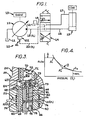
- the control circuit is torque limiting since the modulated load pressure signal is a function of both pump discharge pressure and pump displacement, i.e., the load pressure signal thus becomes a function of pump torque. This relationship is graphically illustrated in Figure 4 wherein curve A plots pump flow versus the load pressure signal and wherein curve B represents a horsepower curve for a particular engine.
- Figure 1 illustrates a fluid circuit 10 comprising a variable displacement pump 11 adapted to communicate pressurized fluid from a source 12 to a fluid actuator 13 under the control of a directional control valve 14.
- a prime mover 15 such as an internal combustion engine, is adapted to drive pump 11 which may take the form of a hydraulic pump of the type shown in Figure 2.
- actuator 13 constitutes a double-acting hydraulic cylinder adapted for use in construction vehicles and the like in a conventional manner.
- servo-system 22 includes a so-called "load-plus” valve 23 ( Figure 2) for maintaining pump discharge pressure P o in line 18 at a specified level above load pressure signal P L in line 20 and a modulating means or horsepower limiting valve 24 for modulating load pressure signal P L ,
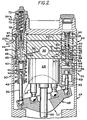
- pump 11 comprises a barrel 25 adapted to be driven by an output shaft 26 of engine 15, a plurality of reciprocal pistons 27 connected to a control member or swash plate 28, and a housing 29 enclosing the pump assembly.
- the displacement of pump 11 is determined by the rotational orientation of swash plate 28 which has opposite sides thereof connected to first and second biasing means 30 and 31 by rods 32 and 33, respectively.
- swash plate 28 will effect maximum pump displacement, whereas horizontal orientation of the swash plate in Figure 2 will effect zero or minimum displacement of the pump.
- Second biasing means 31 may be considered to include "load-plus" valve 23, which functions substantially identically to the corresponding valve disclosed in above-referenced U.S. Patent No. 4,116,587.
- pump discharge pressure P D in a main discharge passage 35 will communicate with branch passages 36 and 37, connected to first and second biasing means 30 and 31, respectively.
- Branch passage 36 communicates discharge pressure to an actuating chamber 38 of biasing means 30 via a port 39 formed in a tubular member 40 secured within housing 29.
- the force generated by fluid pressure in chamber 38 will tend to urge swash plate 28 counterclockwise in Figure 2, towards its maximum displacement position shown, by acting on a piston 41 and rod 32.
- Such force is additive to the force of a compression coil spring 42 which is mounted between member 40 and a retainer 43 mounted on a lower end of piston 41.
- Second branch passage 37 communicates pump discharge pressure to an annulus 44 to communicate such pressure to valve 23, via ports 45 and 46.
- Spool 34 of valve 23 has lands 47, 48, and 49 formed thereon to define annuluses 50 and 51 about the spool.
- Spool 34 is slidably mounted in a bore 52 defined in a tubular member 53 secured within housing 29 with the bore being blocked at the lower end of the spool by a plug 54.
- An actuating chamber 55 is thus between reciprocal spool 34 and plug 54 and another actuating chamber 56 is defined between the plug and a piston 57 attached to rod 33.
- pump discharge pressure communicated to branch passage 37 is communicated to actuating chamber 55 via port 46 and a longitudinal passage 58 formed in spool 34 to shift the spool upwardly in Figure 2 under certain operating conditions, against the opposed biasing force of a compression coil spring 59 and the fluid pressure prevalent in an actuating chamber 60.
- Chamber 60 is adapted to have load pressure signal P L communicated thereto via passage 20'.
- modulating means 24 for modulating load pressure signal P L in line 20' to continuously vary and automatically reset the displacement of pump 11.
- modulating means 24 includes a first spool 65 reciprocally mounted in a bore 66, defined in member 40, and a second spool 67 reciprocally mounted in a bore 68 defined in spool 65.
- a stop shown in the form of a cross pin 69, is secured within spool 65 to limit downward movement of spool 67, as shown in Figure 3.
- Spool 65 is urged downwardly in Figures 2 and 3 by a first compression coil spring 70 of a two-stage biasing means 71 which further includes a second compression coil spring 72.
- a lower end of spring 70 seats on a retainer 73 which receives an upper end of spool 67 therein.
- Load pressure signal P L communicated to modulating means 24 by line 20 will enter an annulus 74 and communicate to an actuating chamber 75 via a port 76 defined in member 40, an annulus 77 defined on spool 65, and a port 78 formed in the spool.
- pressurized fluid communicated to chamber 75 will act on the lower end of piston 67 to urge it upwardly against the opposed biasing force of spring 70 to initiate modulation of load pressure signal P L , as depicted at point A 1 in Figure 4.
- load pressure signal P L will be modulated through metering slots 79 defined on spool 67, which are in communication on their upstream side with chamber 75 via a passage 80 and ports 81 and on their downstream side with a drain passage 82 upon opening thereof.
- This modulation of fluid will cause a fluid flow through orifice 21, creating a pressure drop thereacross to cause load pressure signal P L to become less in passage 20' than in line 20.
- second spring 72 may be employed in cooperation with spring 70 to restage the modulation feature, as depicted at point A 2 in Figure 4.
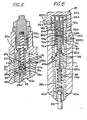
- Figure 5 illustrates a second horsepower limiting or modulating means embodiment 24a which functions similar to modulating means 24, described above.
- Identical numerals depict corresponding constructions and arrangements of the respective modulating means, with numerals depicting modified constructions in Figure 5 being accompanied by an "a”.
- load pressure signal P L communicated to modulating means 24a by line 20 will pass through fixed orifice 21 and communicate to passage 20'.
- Load pressure signal P L ' will also communicate with an actuating chamber 75a, via annulus 74, port 76, an annulus 77a formed on a sleeve-like spool 65a, and ports 78a formed in the spool proper and a plug 65a' thereof.
- Spool 65a is reciprocally mounted in a tubular member 40a, having rod 83 of the follow-up linkage reciprocally mounted therein in a manner similar to that shown in Figure 2.
- a poppet 67a is biased downwardly against a seat formed on plug 65a' and defining a variable orifice 84a thereat by a compresssion coil spring 70a of a biasing means 71a.
- Poppet 67a will thus control venting of load pressure signal P L from chamber 75a to drain passage 82 to thus control the operation of "load-plus” valve 23 ( Figure 2) via passage 20'.
- the maximum desired pressure for a given displacement setting of pump 11, which is communicated to chamber 75a will tend to open poppet valve 67a to vent the load pressure signal to reduce the displacement of the pump.
- a subsequent follow-up action will be effected by rod 83 moving upwardly to close poppet valve 67a at a position which has increased the force imposed on the poppet by spring 70a.
- poppet 67a and its seat on plug 65a', defining variable orifice 84a will function substantially in the manner described in respect to modulating means 24 whereby the feedback from the pivoting of swash plate 28 will vary the force of spring 70a to infinitely adjust the load pressure setting in proportion to the position of the swash plate, so that a pump displacement reduces, system pressure will become proportionately higher and still not overcome maximum available horsepower.
- Figure 6 illustrates a third horsepower limiting or modulating means embodiment 24b which functions similar to modulating means 24 and 24a with one of the differences being that modulation of load pressure signal P L is accomplished by a pair of variable orifices 21b and 84b in series rather than by a series of one fixed orifice 21 and a variable orifice 84 or 84a.
- Identical numerals appearing in Figure 6 also depict corresponding constructions with numerals depicting modified constructions being accompanied by a "b" in Figure 6.
- Load pressure signal P L communicated to modulating means 24b via line 20, is adapted to communicate with passage 20' leading to "load-plus” valve 23 ( Figure 2) after undergoing a pressure drop across variable orifice 21 b.
- the size of orifice 21 b will vary depending on the reciprocal position of a spool 65b.
- load pressure signal P L is communicated to passage 20' via passages 85 defined by a plurality of flat surfaces formed on the periphery of spool 65b, an annulus 66b, ports 76, and annulus 74. Simultaneously therewith, reduced load pressure signal P L will communicate from annulus 66b to an actuating chamber 75b, defined in spool 65b, via one or more ports 78b formed in spool 65b.
- a slug 67b has its upper end disposed in engagement with housing 29 and has its lower end seated on the exit end of chamber 75b to define a second variable orifice 84b thereat.
- a compression coil spring 70b of a biasing means 71 b has its lower end engaged on a retainer 87 which engages a rod 83b of a follow-up linkage.
- the follow-up linkage further includes a compression coil spring 42b disposed between a retainer 88 secured to a lower end of rod 83b and a piston 41 b, engaged with rod 32.
- branch passage 36 communicating with the pump discharge, further communicates with an actuating chamber 38b within the follow-up linkage via passages 39b.
- spool 65b is normally urged upwardly in Figure 6 by spring 70b to provide substantial open communication from line 20 to line 20'.
- Load pressure signal P L prevalent in actuating chamber 75b acts againstthe tower end of slug 67b to exert a downward force on spool 65b in opposition to spring 70b.
- spool 65b will move downwardly to create a variable orifice at 84b to vent load pressure signal P L to drain via drain passages 82b' and 82b, the periphery of retainer 73b being slotted for this purpose.
- Figure 7 illustrates a fourth horsepower limiting or modulating means embodiment 24c wherein identical numerals depict corresponding constructions, but wherein numerals depicting modified constructions are accompanied by a "c".
- Modulating means 24c functions similar to above-described modulating means 24, 24a, and 24b and is further associated with a hereinafter described override means 89 for selectively overriding the automatic function of modulating means 24c. It should become obvious to those skilled in the arts relating hereto that override means 89 could be also associated with modulating means 24, 24a, and 24b with minor modification to these systems.
- Load pressure signal P L communicates to modulating means 24c through line 20 and fixed orifice 21 in passage 20', connected to chamber 60 of "load-plus” valve 23 ( Figure 2).
- Load pressure signal P L communicates to an actuating chamber 75c, via annulus 74, port 76, an annulus 77c, and radial ports 78c formed in a rod 83c which is attached to a piston (not shown), similar to piston 41 in Figure 2.
- a piston or spool 67c is reciprocally mounted in rod 83c to selectively communicate chamber 74c with a drain passage 82c, through variable orifices 84c formed in the rod.
- Piston 67c is biased downwardly to cover orifices 84c by a compression coil spring 70c, having its lower end seated on a cup-shaped retainer 73c. It should be further noted that an upper end of piston 67c engages retainer 73c to act against spring 70c to provide the type of follow-up and resetting function described above.
- Override means 89 includes a piston 90 adapted to apply a counteracting and overriding force to rod 83c, additive to the force of spring 70c, upon the selective pressurization of an actuating chamber 91.
- Chamber 91 is connected to a control 92, such as the steering valve of a construction vehicle, whereby orifices 84c, when opened by upward movement of piston 67c, can be closed upon pressurization of the chamber which forces piston 90 downwardly.
- load-plus valve 23 will function as a conventional pressure compensated flow control valve operating in a normal manner throughout the working range of pump 11 to provide a load-sensitive control of pump discharge pressure P D in line 18, relative to load pressure signal P L by continuously providing a margin between these pressures, as described in above-referenced U.S. Patent No. 4,116,587.
- load pressure signal P L reaches the desired maximum for a given displacement setting of pump 11, representative of the usable horsepower available from the engine, the load pressure signal P L in actuating chamber 75 ( Figure 3) will initiate upward movement of spool 67 against the opposed biasing force of spring 70 until metering slots 79 open to form a variable orifice at 84.
- modulating means 24 This interaction within modulating means 24 will permit pump 11 to continue to operate at such a higher pressure setting without exceeding the horsepower limitations of the engine. Should the load carried by cylinder 13 demand an even greater pressure, the cycle will be repeated. It should be noted in Figure 4 that engagement of spring retainer 73 with second spring 72 of biasing means 71 will permit a restaging of the load pressure and pump displacement, as reflected at point A 2 on curve A. This cyclic action of modulating means 24 and interassociated biasing means 30 and 31 will continue throughout the working pressure range of pump 11 until spool 65 contacts shoulder 65' ( Figure 3), as reflected at point A3 on curve A in Figure 4. This establishes the maximum pressure obtained and further decreasing pump displacement will not increase maximum pressure obtained.
- control system thus provides an infinitely variable horsepower limiting mechanism which will closely follow horsepower curve B of the engine to provide maximum work efficiency with minimum energy consumption or specified hydraulic circuit condition of operation.
- Fixed orifice 21 will ensure that actuating chamber 60 of "load-plus” valve 23 can be bled-off at a sufficiently high rate to provide quick response of "load - plus” valve 23.
- modified modulating means 24a, 24b, and 24c will function similar to modulating means 24.
- override means 89 ( Figure 7) can be readily adapted for use with any one of the modulating means to selectively override the automatic functions thereof.
Landscapes
- Engineering & Computer Science (AREA)
- Mechanical Engineering (AREA)
- General Engineering & Computer Science (AREA)
- Control Of Positive-Displacement Pumps (AREA)
- Fluid-Pressure Circuits (AREA)
- Reciprocating Pumps (AREA)
- Control Of Fluid Gearings (AREA)
Applications Claiming Priority (1)
| Application Number | Priority Date | Filing Date | Title |
|---|---|---|---|
| PCT/US1980/001195 WO1982001047A1 (en) | 1980-09-12 | 1980-09-12 | Torque and high pressure limiting control for variable displacement pumps |
Publications (3)
| Publication Number | Publication Date |
|---|---|
| EP0059709A1 EP0059709A1 (en) | 1982-09-15 |
| EP0059709A4 EP0059709A4 (en) | 1984-04-27 |
| EP0059709B1 true EP0059709B1 (en) | 1987-07-29 |
Family
ID=22154543
Family Applications (1)
| Application Number | Title | Priority Date | Filing Date |
|---|---|---|---|
| EP81901178A Expired EP0059709B1 (en) | 1980-09-12 | 1980-09-12 | Torque and high pressure limiting control for variable displacement pumps |
Country Status (5)
| Country | Link |
|---|---|
| EP (1) | EP0059709B1 (OSRAM) |
| JP (1) | JPS57501393A (OSRAM) |
| BE (1) | BE888823A (OSRAM) |
| DE (1) | DE3071999D1 (OSRAM) |
| WO (1) | WO1982001047A1 (OSRAM) |
Families Citing this family (5)
| Publication number | Priority date | Publication date | Assignee | Title |
|---|---|---|---|---|
| US4854125A (en) * | 1987-02-20 | 1989-08-08 | Honda Giken Kogyo Kabushiki Kaisha | Hydrostatically operated continuously variable transmission |
| US4999020A (en) * | 1989-11-30 | 1991-03-12 | Lucas Aerospace Power Transmission Corp. | Variable displacement high pressure pump with internal power limiting arrangement |
| US5655463A (en) * | 1995-06-19 | 1997-08-12 | Douglas Nagel | Apparatus and method for burning waste material |
| GB2502824A (en) * | 2012-06-08 | 2013-12-11 | Water Hydraulics Company Ltd | Axial piston variable stroke hydraulic machine |
| WO2015048635A1 (en) | 2013-09-27 | 2015-04-02 | Duke University | Mper-liposome conjugates and uses thereof |
Family Cites Families (2)
| Publication number | Priority date | Publication date | Assignee | Title |
|---|---|---|---|---|
| US4034564A (en) * | 1976-01-23 | 1977-07-12 | Caterpillar Tractor Co. | Piston pump assembly having load responsive controls |
| US3999892A (en) * | 1976-02-09 | 1976-12-28 | Caterpillar Tractor Co. | Interconnected pump control means of a plurality of pumps |
-
1980
- 1980-09-12 EP EP81901178A patent/EP0059709B1/en not_active Expired
- 1980-09-12 DE DE8181901178T patent/DE3071999D1/de not_active Expired
- 1980-09-12 JP JP56501521A patent/JPS57501393A/ja active Pending
- 1980-09-12 WO PCT/US1980/001195 patent/WO1982001047A1/en not_active Ceased
-
1981
- 1981-05-15 BE BE0/204803A patent/BE888823A/fr not_active IP Right Cessation
Also Published As
| Publication number | Publication date |
|---|---|
| EP0059709A4 (en) | 1984-04-27 |
| WO1982001047A1 (en) | 1982-04-01 |
| JPS57501393A (OSRAM) | 1982-08-05 |
| DE3071999D1 (en) | 1987-09-03 |
| BE888823A (fr) | 1981-11-16 |
| EP0059709A1 (en) | 1982-09-15 |
Similar Documents
| Publication | Publication Date | Title |
|---|---|---|
| US4379389A (en) | Horsepower consumption control for variable displacement pumps | |
| US3797245A (en) | Dual range pressure dependent variable flow fluid delivery system | |
| US4293284A (en) | Power limiting control apparatus for pressure-flow compensated variable displacement pump assemblies | |
| US3726093A (en) | Pump control system | |
| US4381646A (en) | Torque and high pressure limiting control for variable displacement pumps | |
| US4355510A (en) | Unloading means for flow-pressure compensated valve | |
| EP0059709B1 (en) | Torque and high pressure limiting control for variable displacement pumps | |
| US4116587A (en) | Load plus differential pressure compensator pump control assembly | |
| US4034564A (en) | Piston pump assembly having load responsive controls | |
| US4381647A (en) | Load-plus valve for variable displacement pumps | |
| US3738111A (en) | Variable displacement pump control system | |
| US5454223A (en) | Hydraulic load sensing system with poppet valve having an orifice therein | |
| US4067193A (en) | Combined hydrostatic transmission implement system | |
| US4862691A (en) | Pump drive speed regulator with control-pressure-generating valve having spring biased by cam face on load directional control valve | |
| JPH07279906A (ja) | 油圧制御装置 | |
| US3996744A (en) | Automatic control for hydraulic power transmission | |
| US4332531A (en) | Variable displacement pump with torque limiting control | |
| EP0059710A4 (en) | MULTIPLE PUMP SYSTEM WITH POWER LIMIT CONTROL. | |
| US4336003A (en) | Crane swing control | |
| CA1176137A (en) | Multiple pump system with horsepower limiting control | |
| EP0060247A1 (en) | Unloading means for flow-pressure compensated valve | |
| EP0059712B1 (en) | Improved load-plus valve for variable displacement pumps | |
| CA1166934A (en) | Unloading means for flow-pressure compensated valve | |
| CA1151977A (en) | Flow pressure compensated control for variable displacement pumps | |
| SU1167282A1 (ru) | Гидропривод бульдозера |
Legal Events
| Date | Code | Title | Description |
|---|---|---|---|
| PUAI | Public reference made under article 153(3) epc to a published international application that has entered the european phase |
Free format text: ORIGINAL CODE: 0009012 |
|
| AK | Designated contracting states |
Kind code of ref document: A1 Designated state(s): DE FR GB |
|
| 17P | Request for examination filed |
Effective date: 19820331 |
|
| RBV | Designated contracting states (corrected) |
Designated state(s): DE FR GB |
|
| RAP1 | Party data changed (applicant data changed or rights of an application transferred) |
Owner name: CATERPILLAR INC. |
|
| GRAA | (expected) grant |
Free format text: ORIGINAL CODE: 0009210 |
|
| AK | Designated contracting states |
Kind code of ref document: B1 Designated state(s): DE FR GB |
|
| REF | Corresponds to: |
Ref document number: 3071999 Country of ref document: DE Date of ref document: 19870903 |
|
| ET | Fr: translation filed | ||
| PLBE | No opposition filed within time limit |
Free format text: ORIGINAL CODE: 0009261 |
|
| STAA | Information on the status of an ep patent application or granted ep patent |
Free format text: STATUS: NO OPPOSITION FILED WITHIN TIME LIMIT |
|
| 26N | No opposition filed | ||
| PGFP | Annual fee paid to national office [announced via postgrant information from national office to epo] |
Ref country code: FR Payment date: 19890809 Year of fee payment: 10 |
|
| PGFP | Annual fee paid to national office [announced via postgrant information from national office to epo] |
Ref country code: GB Payment date: 19890831 Year of fee payment: 10 |
|
| PGFP | Annual fee paid to national office [announced via postgrant information from national office to epo] |
Ref country code: DE Payment date: 19890912 Year of fee payment: 10 |
|
| PG25 | Lapsed in a contracting state [announced via postgrant information from national office to epo] |
Ref country code: GB Effective date: 19900912 |
|
| GBPC | Gb: european patent ceased through non-payment of renewal fee | ||
| PG25 | Lapsed in a contracting state [announced via postgrant information from national office to epo] |
Ref country code: FR Effective date: 19910530 |
|
| PG25 | Lapsed in a contracting state [announced via postgrant information from national office to epo] |
Ref country code: DE Effective date: 19910601 |
|
| REG | Reference to a national code |
Ref country code: FR Ref legal event code: ST |