EP0059552B1 - Elektronische Zündschaltung für Lampen - Google Patents
Elektronische Zündschaltung für Lampen Download PDFInfo
- Publication number
- EP0059552B1 EP0059552B1 EP82300786A EP82300786A EP0059552B1 EP 0059552 B1 EP0059552 B1 EP 0059552B1 EP 82300786 A EP82300786 A EP 82300786A EP 82300786 A EP82300786 A EP 82300786A EP 0059552 B1 EP0059552 B1 EP 0059552B1
- Authority
- EP
- European Patent Office
- Prior art keywords
- circuit
- starter
- ignitor
- progressive
- threshold
- Prior art date
- Legal status (The legal status is an assumption and is not a legal conclusion. Google has not performed a legal analysis and makes no representation as to the accuracy of the status listed.)
- Expired
Links
- 239000007858 starting material Substances 0.000 title claims description 29
- 230000000750 progressive effect Effects 0.000 claims description 17
- 230000003247 decreasing effect Effects 0.000 claims description 3
- 230000003993 interaction Effects 0.000 claims description 3
- 230000003467 diminishing effect Effects 0.000 claims description 2
- 230000000630 rising effect Effects 0.000 claims description 2
- 239000003990 capacitor Substances 0.000 description 7
- 230000000694 effects Effects 0.000 description 2
- 230000001960 triggered effect Effects 0.000 description 2
- 238000010438 heat treatment Methods 0.000 description 1
- 229910052743 krypton Inorganic materials 0.000 description 1
- DNNSSWSSYDEUBZ-UHFFFAOYSA-N krypton atom Chemical compound [Kr] DNNSSWSSYDEUBZ-UHFFFAOYSA-N 0.000 description 1
- 238000004519 manufacturing process Methods 0.000 description 1
- 230000010355 oscillation Effects 0.000 description 1
- 230000001502 supplementing effect Effects 0.000 description 1
Images
Classifications
-
- H—ELECTRICITY
- H05—ELECTRIC TECHNIQUES NOT OTHERWISE PROVIDED FOR
- H05B—ELECTRIC HEATING; ELECTRIC LIGHT SOURCES NOT OTHERWISE PROVIDED FOR; CIRCUIT ARRANGEMENTS FOR ELECTRIC LIGHT SOURCES, IN GENERAL
- H05B41/00—Circuit arrangements or apparatus for igniting or operating discharge lamps
- H05B41/02—Details
- H05B41/04—Starting switches
- H05B41/042—Starting switches using semiconductor devices
- H05B41/044—Starting switches using semiconductor devices for lamp provided with pre-heating electrodes
- H05B41/046—Starting switches using semiconductor devices for lamp provided with pre-heating electrodes using controlled semiconductor devices
Definitions
- This invention relates to electronic starter circuits for discharge lamps and it relates especially, though not exclusively, to such circuits for krypton filled fluorescent lamps.
- Some such lamps especially those which are slimmer than conventional fluorescent lamps (e.g. 25 mm diameter as opposed to 38 mm diameter), tend to be rather difficult to start and this invention provides an electonic starter circuit which is capable of overcoming that difficulty.
- a starter circuit which is used in practice for conventional fluorescent lamps is the progressive starter circuit such as that described and claimed in US-A-4165475 the disclosure of which is incorporated herein by reference.
- This circuit employs progressive triggering such that triggering pulses are generated in successive cycles or half cycles of mains voltage in response to the mains voltage exceeding a threshold level which increases steadily cycle by cycle. This progression continues until the threshold level reaches a predetermined value, preferably greater than the supply voltage.
- a predetermined value preferably greater than the supply voltage.
- cathode heating current flows until the predetermined value is reached at which time the starter is inactivated and attempts at starting cease.
- This invention consists in supplementing that circuit by connecting an ignitor circuit, in parallel therewith, across the lamp.
- the ignitor circuit is one in which the supply negative swing is rectified to charge a capacitor to around peak mains and on the positive swing a thyristor fires to complete an HF resonant series circuit (ballast and charged capacitor) which executes approximately one cycle and terminates with current attempting to reverse through the thyristor.
- the basic ignitor circuit is well known of itself and a reference to ignitors may be found in "Lamps and Lighting” (Second Edition 1972, Editors: S. T. Henderson and A. M. Marsden Pub. Arnold) Section 18.3.1, pp. 333-334. There is, however, a special and advantageous interaction between the two known circuits as will become clear hereinafter.
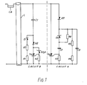
- a discharge lamp starter circuit having two starter input terminals for connection to the cathodes of a discharge lamp, for receiving a cyclically varying voltage supplied through the lamp cathodes and a choke ballast, the circuit comprising, connected in parallel between said terminals, a progressive starter circuit capable of providing to said cathodes a succession of preheat current pulses, of progressively diminishing magnitude in response to a progressively rising threshold and an ignitor circuit capable of providing to said lamp, high voltage ignition pulses in response to a fixed threshold, the arrangement in combination being such that the progressive starter circuit provides the progressively decreasing preheat current pulses until the threshold of the ignitor is exceeded, the ignitor initiates high voltage ignition pulses thereafter, the ignition pulses being terminated prematurely by interaction with the progressive starter circuit which provides substantially constant magnitude preheat pulses until the progressive threshold reaches a preset maximum value whereupon the ignitor circuit provides a full ignition pulse.
- circuit A the progressive starter circuit
- circuit B the ignitor circuit
- circuits A and B independently are well known and thus will not be further described herein. However, with the following component types and values incorporated by way of example, the two circuits interact in a particularly advantageous way, as will be described.
- circuits A and B in parallel with each other, and with the lamp L is effective initially (i.e. for the first few cycles of mains voltage applied to the lamp) so that circuit A only operates, circuit B being arranged to be energised only when the voltage applied thereto exceeds a fixed threshold level.
- the progressive threshold of circuit A (increasing with each cycle of mains voltage applied to the lamp) permits, in known manner, preheat current pulses of steadily decreasing magnitude to be applied to the lamp electrodes.
- circuit A is operative to perheat the lamp electrodes but circuit B not being energised at all due to its fixed operational threshold exceeding that of circuit A
- the variable threshold of circuit A has been increased to a level which exceeds the fixed threshold of circuit B.
- circuit B is energised and attempts, in the usual manner for such an ignitor circuit, to develop a high voltage ignition pulse for the lamp, the voltage consisting of a high freqency oscillation determined by a series resonant circuit governed by the capacitor C1 and the inductance of a lamp choke ballast LB.
- the circuit B develops the expected high frequency pulse which first swings negative, limiting at maximum negative mains voltage, and then attempts to swing to a substantially higher positive voltage.
- This attempt however is frustrated by the pulse triggering circuit A into operation, thus precluding the positive swing of the pulse generated by circuit B exceeding the threshold level of the circuit A for that cycle of mains operation.
- the triggering of circuit A provides another current pulse to the electrodes of the lamp. This state of affairs continues for several cycles of mains voltage, with the positive swing of the voltage pulse generated by circuit B being permitted to increase for each cycle by. the increasing threshold of circuit A.
- the threshold of circuit A has risen high enough for the positive swing of the pulse generated by circuit B to be able to reach its maximum positive value without triggering circuit A into operation. It is then able to ignite the lamp. Once ignition occurs, the low running voltage across the lamp is insufficient to trigger either of circuits A and B into operation and thus these circuits remain quiescent during normal running. It will be understood that preheating of the lamp electrodes ceases when the threshold of circuit A has increased sufficiently to allow the pulse generated by circuit B to attain its maximum positive value.
- circuit A the preheating current pulses generated by circuit A remain of substantially constant magnitude, despite the steadily increasing threshold value of circuit A, because of the fixed threshold of circuit B and the high frequency nature of the voltage pulses generated thereby, since these pulses determine the instant of energisation of circuit A during the successive cycles of mains voltage.
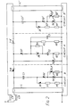
- the resistors R1 and R7 and the diode D2 can be omitted from the circuit.
- a resistor is connected from the junction of the capacitor and the diode thus added to the junction of D6, R4 and C2.
- the added components are effective to rectify the mains voltage to provide a bias current'to capacitor C2, which component established the progressive threshold of operation for circuit A.
- the bias current provides a non-linear progression of the threshold such that if the mains voltage is high, the ultimate cessation of production of current pulses by circuit A occurs sooner than it would have done if linear progression had been used, and vice-versa.
Landscapes
- Circuit Arrangements For Discharge Lamps (AREA)
Claims (3)
Applications Claiming Priority (2)
| Application Number | Priority Date | Filing Date | Title |
|---|---|---|---|
| GB8105901 | 1981-02-25 | ||
| GB8105901 | 1981-02-25 |
Publications (2)
| Publication Number | Publication Date |
|---|---|
| EP0059552A1 EP0059552A1 (de) | 1982-09-08 |
| EP0059552B1 true EP0059552B1 (de) | 1987-02-04 |
Family
ID=10519950
Family Applications (1)
| Application Number | Title | Priority Date | Filing Date |
|---|---|---|---|
| EP82300786A Expired EP0059552B1 (de) | 1981-02-25 | 1982-02-16 | Elektronische Zündschaltung für Lampen |
Country Status (2)
| Country | Link |
|---|---|
| EP (1) | EP0059552B1 (de) |
| DE (1) | DE3275429D1 (de) |
Family Cites Families (2)
| Publication number | Priority date | Publication date | Assignee | Title |
|---|---|---|---|---|
| CA1155170A (en) * | 1979-03-22 | 1983-10-11 | Isao Kaneda | Discharge lamp lighting device with a delayed-output oscillation circuit |
| FR2488095A1 (fr) * | 1980-08-01 | 1982-02-05 | Lampes Sa | Starter electronique pour lampe fluorescente |
-
1982
- 1982-02-16 DE DE8282300786T patent/DE3275429D1/de not_active Expired
- 1982-02-16 EP EP82300786A patent/EP0059552B1/de not_active Expired
Non-Patent Citations (1)
| Title |
|---|
| S. T. Henerson and A. M. Marsden "Lamps and Lighting", second edition, 1972, section 18.3.1, pp. 333-334 * |
Also Published As
| Publication number | Publication date |
|---|---|
| DE3275429D1 (en) | 1987-03-12 |
| EP0059552A1 (de) | 1982-09-08 |
Similar Documents
| Publication | Publication Date | Title |
|---|---|---|
| US5047694A (en) | Lamp starting circuit | |
| US4461980A (en) | Protection circuit for series resonant electronic ballasts | |
| US4766350A (en) | Electric circuit with transient voltage doubling for improved operation of a discharge lamp | |
| US5027032A (en) | Electronically controlled magnetic fluorescent lamp ballast | |
| US3643127A (en) | Electronic gas discharge tube starter having a semiconductor switch element controlled by a capacitive voltage divider | |
| US4209730A (en) | Starting circuit for gaseous discharge lamps | |
| US4464607A (en) | Lighting unit | |
| US4893059A (en) | Electronic ballast with safety feature | |
| US5059870A (en) | Electronic solid state starter for fluorescent lamps | |
| EP0158390B1 (de) | Gleich-/Wechselstrom-Wandler zum Starten und Speisen einer Gas- und/oder Dampf-Entladungslampe | |
| US4323824A (en) | Low voltage fluorescent operating circuit | |
| GB1533646A (en) | Starter switch for starting a discharge lamp | |
| US3771017A (en) | Phase controlled firing circuit | |
| EP0059552B1 (de) | Elektronische Zündschaltung für Lampen | |
| US4749909A (en) | Compact igniter for discharge lamps | |
| US4994716A (en) | Circuit arrangement for starting and operating gas discharge lamps | |
| US4358711A (en) | Circuit arrangement for starting and operating a gas- and/or vapor discharge lamp | |
| US4642521A (en) | Compact igniter for discharge lamps | |
| US4069442A (en) | Pulse circuit for gaseous discharge lamps | |
| US4092565A (en) | Pulse circuit for gaseous discharge lamps | |
| EP0011410B1 (de) | Elektronische Starterschaltungen für Entladungslampen | |
| EP0034401B1 (de) | Schaltung für Entladungslampen | |
| US20110050115A1 (en) | Method and igniter for igniting a gas discharge lamp | |
| US6603275B2 (en) | Electronic starter for fluorescent lamps | |
| US4926096A (en) | Shock-protected electronic ballast |
Legal Events
| Date | Code | Title | Description |
|---|---|---|---|
| PUAI | Public reference made under article 153(3) epc to a published international application that has entered the european phase |
Free format text: ORIGINAL CODE: 0009012 |
|
| AK | Designated contracting states |
Designated state(s): DE GB NL |
|
| 17P | Request for examination filed |
Effective date: 19830121 |
|
| GRAA | (expected) grant |
Free format text: ORIGINAL CODE: 0009210 |
|
| AK | Designated contracting states |
Kind code of ref document: B1 Designated state(s): DE GB NL |
|
| REF | Corresponds to: |
Ref document number: 3275429 Country of ref document: DE Date of ref document: 19870312 |
|
| PLBE | No opposition filed within time limit |
Free format text: ORIGINAL CODE: 0009261 |
|
| STAA | Information on the status of an ep patent application or granted ep patent |
Free format text: STATUS: NO OPPOSITION FILED WITHIN TIME LIMIT |
|
| 26N | No opposition filed | ||
| PGFP | Annual fee paid to national office [announced via postgrant information from national office to epo] |
Ref country code: DE Payment date: 19920416 Year of fee payment: 11 |
|
| PGFP | Annual fee paid to national office [announced via postgrant information from national office to epo] |
Ref country code: GB Payment date: 19930204 Year of fee payment: 12 |
|
| PGFP | Annual fee paid to national office [announced via postgrant information from national office to epo] |
Ref country code: NL Payment date: 19930228 Year of fee payment: 12 |
|
| PG25 | Lapsed in a contracting state [announced via postgrant information from national office to epo] |
Ref country code: DE Effective date: 19931103 |
|
| PG25 | Lapsed in a contracting state [announced via postgrant information from national office to epo] |
Ref country code: GB Effective date: 19940216 |
|
| PG25 | Lapsed in a contracting state [announced via postgrant information from national office to epo] |
Ref country code: NL Effective date: 19940901 |
|
| GBPC | Gb: european patent ceased through non-payment of renewal fee |
Effective date: 19940216 |
|
| NLV4 | Nl: lapsed or anulled due to non-payment of the annual fee |