EP0059127A1 - Dispositif de visée stabilisée à deux voies optiques - Google Patents
Dispositif de visée stabilisée à deux voies optiques Download PDFInfo
- Publication number
- EP0059127A1 EP0059127A1 EP82400185A EP82400185A EP0059127A1 EP 0059127 A1 EP0059127 A1 EP 0059127A1 EP 82400185 A EP82400185 A EP 82400185A EP 82400185 A EP82400185 A EP 82400185A EP 0059127 A1 EP0059127 A1 EP 0059127A1
- Authority
- EP
- European Patent Office
- Prior art keywords
- reflector
- rotation
- axis
- reflectors
- parallel
- Prior art date
- Legal status (The legal status is an assumption and is not a legal conclusion. Google has not performed a legal analysis and makes no representation as to the accuracy of the status listed.)
- Withdrawn
Links
Images
Classifications
-
- G—PHYSICS
- G02—OPTICS
- G02B—OPTICAL ELEMENTS, SYSTEMS OR APPARATUS
- G02B27/00—Optical systems or apparatus not provided for by any of the groups G02B1/00 - G02B26/00, G02B30/00
- G02B27/64—Imaging systems using optical elements for stabilisation of the lateral and angular position of the image
- G02B27/644—Imaging systems using optical elements for stabilisation of the lateral and angular position of the image compensating for large deviations, e.g. maintaining a fixed line of sight while a vehicle on which the system is mounted changes course
Definitions
- the present invention relates to a sighting device with two optical channels, in particular for a periscope.
- French Patent No. 2,273,291 shows an observation head for a periscope comprising two optical devices, one for daytime observation, the other for nighttime observation, these two optical devices being simultaneously orientable from so that the two light beams they receive are beams of the same direction therefore coming from the same place in space.
- the two reflectors intercepting the two optical channels are mounted on the same horizontal axis of rotation.
- this arrangement is inconvenient because it imposes on the observation head a width at least equal to the sum of the widths of the two reflectors.
- the present invention aims to overcome these two major drawbacks by providing a sighting device with two parallel optical paths comprising a first and a second reflector each intercepting an optical path, the first reflector being able to rotate around a first axis of rotation, the second reflector which can rotate about a second axis of rotation, these two axes of rotation being parallel, these reflectors being arranged at a certain distance from each other.
- a gyroscopic effect stabilizer is provided, the angular position of its outlet axis of which is maintained in a constant ratio with respect to the angular position of the first reflector, as well as a means for establishing a constant angular relationship between the angular positions of these two reflectors around their axis of rotation.
- the first reflector can rotate around an axis making an angle of 45 ° with its plane of reflection, that the axis of exit of the gyroscopic stabilizer is in the extension and is integral with the axis of rotation of the first reflector, that the second reflector can rotate around an axis parallel to its plane of reflection, and that it is established between the two axes of rotation of the two reflectors a constant angular relationship such that the ratio of the rotation of the second reflector to the rotation of the first is equal to half.
- This particular arrangement of the first reflector is in fact such that, according to a well-known optical principle, an alpha rotation of the incident ray moving in a plane perpendicular to the axis of rotation of the reflector implies for this reflector an identical rotation alpha for keep the same direction of the reflected ray.
- the inertial stabilizer can be directly coupled to the first reflector. This avoids an additional axis of rotation and an entire kinematic chain, hence a reduction in size, cost and an increase in - precision by eliminating certain clearances and friction.
- At least one mirror or prism is provided which intercepts the light beam coming from the first reflector and, by simple or double reflection, brings it back in a direction parallel to the light beam coming from the second reflector.
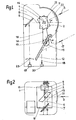
- Figure 1 shows schematically in side view a first embodiment of the sighting device according to the invention.
- FIG. 2 is a top view of the device shown in FIG. 1.
- a first reflector intercepting the first optical channel constituted in this embodiment by a mirror 2 rigidly fixed to a shaft 3 arranged in the box 1 so as to be able to turn on itself according to a horizontal axis of rotation 4.
- the reflection plane 2 of the first mirror makes an angle of 45 ° with its shaft 3 and therefore also with its axis of rotation 4.
- a first light beam 5 intended to be observed reaches the mirror 2 in a direction situated in a plane perpendicular to the axis of rotation 4.
- the beam 5 makes with the horizontal an angle alpha which is the site angel.
- the mirror 2 is then oriented relative to the light beam so that the beam has an incidence of 45 ° with this mirror.
- the mirror is in fact rotated by the value of the angle alpha corresponding to the angle of elevation.
- This first light beam. 5 then undergoes a first reflection to follow a path 6 which is in fact merged with the horizontal axis 4 of rotation of the mirror 2, this beam then strikes a mirror complementary 7 which is rigidly connected to the housing 1.
- the reflection plane of the mirror 7 is vertical and makes an angle of 45 ° with the axis 4.
- the light beam is then reflected on this mirror 7 and follows a horizontal path 8 which brings it to another mirror 9 which is rigidly connected to the housing 1 and which is in a plane located at 45 ° from the vertical so as to return the light beam coming from path 8 downwards in a direction vertical 10.
- the mirror 2 is mounted on the shaft 3 which can rotate in the housing 1 and which is in fact merged with the output shaft of the gyroscopic stabilizer.
- This stabilizer 11 is used to keep the inclination of the mirror 2 relative to the horizontal constant whatever the rotational movements around a horizontal axis that the box 1 may have.
- a second reflector intercepting the second optical path constituted in this embodiment by a mirror 12, is located substantially below the mirror 2, and is arranged in the housing 1 so as to be able to rotate around an axis 13 which is horizontal and parallel to the axis 4.
- This mirror 12 has a reflection plane which is parallel to its axis of rotation 13.
- a mechanical transmission essentially comprising two pulleys 14 and 15 and a belt 16 connects the shafts of rotation of the two mirrors 2 and 12 so as to establish a constant angular relationship between these two mirrors. This angular relationship is such that for an alpha rotation of the mirror 2 the mirror 12 undergoes a rotation equal to alpha over 2. This can be achieved for example by using a pulley 14 whose diameter is half the diameter of the pulley 15.
- This mirror 12 intercepts the second light beam 17 from the second optical channel.
- the mirror 12 is then placed at 45 ° so as to return the light beam vertically downwards following the path 18
- the ratio k between the rotation of the mirrors 2 and 12 causes a reflection of the two light beams 5 and 17 which follows paths 10 and 18 which remain well parallel to each other. in a fixed position relative to the housing.
- the two observation devices 19, 20 of optical channels arranged on paths 10 and 18 do indeed simultaneously give a stabilized image of the two parallel optical channels 5 and 17.
- the means establishing the constant angular relationship between the mirrors 2 and 12 produced mechanically can be made by any other method such as electrical copying, position control, etc.
- Certain secondary arrangements can be adapted to this device.
- One can for example have a spherical porthole 21 centered around the mirror 2.
- a corrective lens 22 it is also possible to mount between the mirror and the window, on the path of the beam, a corrective lens 22 to correct the optical deformations due to this window.
- the particular arrangement of the mirror 2 arranged at 45 ° relative to its axis of rotation and which rotates by the same angle alpha as the elevation angle means that the lens 22 can be mounted fixed relative to this mirror 2
- the lens 22 can be mounted fixed relative to this mirror 2
Landscapes
- Physics & Mathematics (AREA)
- General Physics & Mathematics (AREA)
- Optics & Photonics (AREA)
- Telescopes (AREA)
Applications Claiming Priority (2)
| Application Number | Priority Date | Filing Date | Title |
|---|---|---|---|
| FR8102384 | 1981-02-06 | ||
| FR8102384A FR2499724A1 (fr) | 1981-02-06 | 1981-02-06 | Dispositif de visee stabilisee a deux voies optiques |
Publications (1)
| Publication Number | Publication Date |
|---|---|
| EP0059127A1 true EP0059127A1 (fr) | 1982-09-01 |
Family
ID=9254929
Family Applications (1)
| Application Number | Title | Priority Date | Filing Date |
|---|---|---|---|
| EP82400185A Withdrawn EP0059127A1 (fr) | 1981-02-06 | 1982-02-04 | Dispositif de visée stabilisée à deux voies optiques |
Country Status (2)
| Country | Link |
|---|---|
| EP (1) | EP0059127A1 (en:Method) |
| FR (1) | FR2499724A1 (en:Method) |
Cited By (2)
| Publication number | Priority date | Publication date | Assignee | Title |
|---|---|---|---|---|
| FR2552893A1 (fr) * | 1983-10-04 | 1985-04-05 | France Etat | Perfectionnements aux appareils d'observation |
| US4695119A (en) * | 1982-01-14 | 1987-09-22 | Barr & Stroud Limited | Infrared optical system |
Citations (4)
| Publication number | Priority date | Publication date | Assignee | Title |
|---|---|---|---|---|
| FR2254037A1 (en) * | 1973-12-10 | 1975-07-04 | Sfim | Optical stabilisation element for viewing axis - concave mirror in objective image plane reflects light to gyroscope mirror |
| US4010365A (en) * | 1973-03-26 | 1977-03-01 | Hughes Aircraft Company | Self-stabilizing image scanner |
| FR2337326A1 (fr) * | 1975-12-29 | 1977-07-29 | Realisations Electronique Et | Appareil d'observation et de visee, notamment sur vehicule |
| FR2461230A1 (fr) * | 1979-07-04 | 1981-01-30 | Wegmann & Co | Dispositif pour la stabilisation de la ligne de visee d'un appareil de visee optique pour une arme |
-
1981
- 1981-02-06 FR FR8102384A patent/FR2499724A1/fr active Granted
-
1982
- 1982-02-04 EP EP82400185A patent/EP0059127A1/fr not_active Withdrawn
Patent Citations (4)
| Publication number | Priority date | Publication date | Assignee | Title |
|---|---|---|---|---|
| US4010365A (en) * | 1973-03-26 | 1977-03-01 | Hughes Aircraft Company | Self-stabilizing image scanner |
| FR2254037A1 (en) * | 1973-12-10 | 1975-07-04 | Sfim | Optical stabilisation element for viewing axis - concave mirror in objective image plane reflects light to gyroscope mirror |
| FR2337326A1 (fr) * | 1975-12-29 | 1977-07-29 | Realisations Electronique Et | Appareil d'observation et de visee, notamment sur vehicule |
| FR2461230A1 (fr) * | 1979-07-04 | 1981-01-30 | Wegmann & Co | Dispositif pour la stabilisation de la ligne de visee d'un appareil de visee optique pour une arme |
Cited By (2)
| Publication number | Priority date | Publication date | Assignee | Title |
|---|---|---|---|---|
| US4695119A (en) * | 1982-01-14 | 1987-09-22 | Barr & Stroud Limited | Infrared optical system |
| FR2552893A1 (fr) * | 1983-10-04 | 1985-04-05 | France Etat | Perfectionnements aux appareils d'observation |
Also Published As
| Publication number | Publication date |
|---|---|
| FR2499724B1 (en:Method) | 1984-08-10 |
| FR2499724A1 (fr) | 1982-08-13 |
Similar Documents
| Publication | Publication Date | Title |
|---|---|---|
| EP0202987B1 (fr) | Dispositif de transport et de combinaison d'images lumineuses, et son utilisation pour un viseur de casque | |
| EP0050539A1 (fr) | Dispositif à imagerie vidéo pour un autodirecteur | |
| BE1010513A4 (fr) | Plate-forme asservie et stabilisee perfectionnee. | |
| EP0487385A1 (fr) | Dispositif de visualisation collimaté à miroir sphérique hors d'axe pour simulateur | |
| EP0104987B1 (fr) | Viseur de pointage tête haute utilisable comme viseur de tir | |
| FR2634289A1 (fr) | Periscope panoramique | |
| FR2727214A1 (fr) | Dispositif de stereomicroscope a objectif commun et de chemins de rayons d'observation stereoscopique utilise dans le domaine de la microchirurgie en ophtalmologie | |
| EP0511346A1 (fr) | Dispositif de controle d'alignement et son application. | |
| FR2458824A1 (fr) | Mecanisme de reglage de l'ecartement interoculaire de jumelles | |
| FR3082690A1 (fr) | Dispositif de veille proximale | |
| FR2673731A1 (fr) | Interrupteur optique. | |
| EP0189217B1 (fr) | Analyseur optico-mécanique ayant un champ de télémétrie fixe | |
| FR2518763A1 (fr) | Ensemble de visee et de pointage jour-nuit | |
| EP0059127A1 (fr) | Dispositif de visée stabilisée à deux voies optiques | |
| EP0068932B1 (fr) | Têtes de visée d'installations périscopiques, notamment pour sous-marins | |
| FR2552893A1 (fr) | Perfectionnements aux appareils d'observation | |
| EP0104114B1 (fr) | Dispositif viseur à miroir holographique, et procédé de fabrication du miroir | |
| FR2530009A1 (fr) | Appareil de visee panoramique stabilisee comprenant un detecteur thermique | |
| FR2478829A1 (fr) | Jumelles optiques a mecanisme de mise au point automatique | |
| FR2548384A1 (fr) | Dispositif a imagerie video, notamment pour autodirecteur | |
| EP0100124A1 (fr) | Système optique d'autodirecteur à imagerie | |
| EP1079215B1 (fr) | Instrument de spectrométrie infrarouge à haute résolution | |
| EP0221606B1 (fr) | Dispositif optique de prise de vue ou de projection | |
| EP0343082B1 (fr) | Appareil pour réaliser le balayage d'un faisceau lumineux rigoureusment plan et parallèle à un axe donné | |
| FR2461230A1 (fr) | Dispositif pour la stabilisation de la ligne de visee d'un appareil de visee optique pour une arme |
Legal Events
| Date | Code | Title | Description |
|---|---|---|---|
| PUAI | Public reference made under article 153(3) epc to a published international application that has entered the european phase |
Free format text: ORIGINAL CODE: 0009012 |
|
| AK | Designated contracting states |
Designated state(s): AT BE CH DE FR GB IT LU NL SE |
|
| 17P | Request for examination filed |
Effective date: 19820909 |
|
| ITF | It: translation for a ep patent filed | ||
| STAA | Information on the status of an ep patent application or granted ep patent |
Free format text: STATUS: THE APPLICATION IS DEEMED TO BE WITHDRAWN |
|
| 18D | Application deemed to be withdrawn |
Effective date: 19850903 |
|
| EUG | Se: european patent has lapsed |
Ref document number: 82400185.3 Effective date: 19860411 |
|
| RIN1 | Information on inventor provided before grant (corrected) |
Inventor name: PREVOST, MARC Inventor name: MOIREZ, JACQUES Inventor name: RAGAIN, JACQUES |