EP0058790B1 - Circular knitting machine - Google Patents
Circular knitting machine Download PDFInfo
- Publication number
- EP0058790B1 EP0058790B1 EP81300764A EP81300764A EP0058790B1 EP 0058790 B1 EP0058790 B1 EP 0058790B1 EP 81300764 A EP81300764 A EP 81300764A EP 81300764 A EP81300764 A EP 81300764A EP 0058790 B1 EP0058790 B1 EP 0058790B1
- Authority
- EP
- European Patent Office
- Prior art keywords
- circular knitting
- knitting machine
- ring gear
- frame
- needle cylinder
- Prior art date
- Legal status (The legal status is an assumption and is not a legal conclusion. Google has not performed a legal analysis and makes no representation as to the accuracy of the status listed.)
- Expired
Links
- 238000009940 knitting Methods 0.000 title claims abstract description 26
- 230000005540 biological transmission Effects 0.000 claims abstract description 41
- 239000004744 fabric Substances 0.000 claims abstract description 32
- 238000013016 damping Methods 0.000 claims abstract description 5
- 239000007787 solid Substances 0.000 abstract 1
- 230000010355 oscillation Effects 0.000 description 8
- 230000033001 locomotion Effects 0.000 description 3
- 230000003292 diminished effect Effects 0.000 description 2
- 229910000831 Steel Inorganic materials 0.000 description 1
- 230000002238 attenuated effect Effects 0.000 description 1
- 230000002301 combined effect Effects 0.000 description 1
- 230000003247 decreasing effect Effects 0.000 description 1
- 230000000593 degrading effect Effects 0.000 description 1
- 230000001419 dependent effect Effects 0.000 description 1
- 230000009699 differential effect Effects 0.000 description 1
- 230000008030 elimination Effects 0.000 description 1
- 238000003379 elimination reaction Methods 0.000 description 1
- 230000001788 irregular Effects 0.000 description 1
- 239000010959 steel Substances 0.000 description 1
- 238000004804 winding Methods 0.000 description 1
Images



Classifications
-
- D—TEXTILES; PAPER
- D04—BRAIDING; LACE-MAKING; KNITTING; TRIMMINGS; NON-WOVEN FABRICS
- D04B—KNITTING
- D04B15/00—Details of, or auxiliary devices incorporated in, weft knitting machines, restricted to machines of this kind
- D04B15/94—Driving-gear not otherwise provided for
Definitions
- the present invention relates to circular knitting machines and more particularly to circular knitting machines of a novel type wherein the needle cylinder is not directly driven by a driving pinion and the distance of power transmission between the driving pinion and the needle cylinder is comparatively lengthened, and in which a vibration or oscillation damping means is provided whereby unbalanced vibration or oscillation occurring on each needle cylinder, which would bring about undesirable horizontal lines upon the knitted fabric during the operation of the knitting machine, is compensated and attenuated.
- undesirable horizontal lines are also caused by reasons other than the above mentioned vibration or oscillation, such as the uneven tension of yarns, the unadequate adjustment of cams, the uneven tension of fabric roll, and so forth. Nevertheless, these causes may easily be eliminated and controlled by adjusting the tension of yarns and fabric, and the correct positioning of cams. And the elimination of these causes cannot totally eliminate the undesirable horizontal lines; there are still lines appearing once on the knitted fabric for each rotation of the needle cylinder.
- a principal object of the invention is to provide an improved circular knitting machine with a new arrangement of driving mechanism for driving the needle cylinder so as to eliminate the undesirable horizontal lines appeared on the knitted fabric caused by the uneven vibrations of the needles point during the machine operation.
- Another object of the invention is to provide an improved circular knitting machine having centre shafts provided with the cylinder and dial to maintain an accurate centre whereby an even rotation of cylinder and dial can be obtained so as to diminish the undesirable horizontal lines on the fabric.
- Still another object of the invention is to provide an improved circular knitting machine having the distance between the direct power input point or the mesh point of driving gear and needle cylinder comparatively lengthened and a vibration dispersing means further provided whereby the undesirable horizontal lines on the knitted fabric is greatly decreased.
- a circular knitting machine comprising: a machine frame having a plurality of legs, a ringshaped supporting table and a base plate at the bottom of the frame, a needle cylinder secured onto a rotating member which is rotatably mounted on the supporting table, a ring gear rotatably mounted in said machine frame, characterised by a transmission device comprising transmission arms connected to said ring gear and for transmitting rotation to the needle cylinder and to a fabric takeup device, and a driving pinion driven by a drive means in mesh with said ring gear to drive said gear thereby to transmit the rotation from said drive means through the transmission device to the needle cylinder.
- a needle cylinder 20 is fixed onto a rotating disc 21 which has a downwardly extending hollow shaft 22 rotatably inserted in the bearings 19 housed within the hub 14.
- a rotating wheel 24 is fixed at the lower end of said shaft 22 by nuts 25 and a key.
- a vibration dispersing device 30 is provided below the supporting table 13 as shown in Figure 1 and Figure 2, in such a manner that one end is fixed on a supporting frame 16, which is separated from said machine frame 10 and provided for installing the motor M and driving means 80 therein.
- the other end of the device 30 is a ring shape free end 31 fixed to the outer periphery of said hub portion 14 by bolts.
- a ring gear 40 for driving said rotating wheel 24 through a transmission means is slidably, rotatably mounted on a rail portion 121 of said supporting ring 12.
- the gear 40 meshes with a driving pinion 41 rotatably supported on a driving shaft 43 at the mesh point 42 and is driven by the driving pinion 41 which is driven by the motor M mounted on said frame 16 through a suitable transmission means 80.
- Said take-up device 5 consists of a pair of brackets 51 having a pair of radial grooves 52 on their upper ends corresponding said transmission arms 45 for engaging with said pin ends 46.
- the downward pin-shaped free ends 46 of said transmission arms 45 are radial slidably inserted into the grooves 52 in the like manner as said pin ends 27 of the transmission arms 26 so as to rotate said roller means 5.
- the driving shaft 43 extends upwardly and passes through said vibration dispersing member 30 and supporting tables 13, 23 so as to drive an automatic yarn feeding device (not shown) and the dial means 6 (shown in dot lines) through suitable transmission gears (not shown). Said shaft 43 is driven by the motor M mounted on the bottom of said frame 16 via a suitable transmission gear 80.
- the hole 17 on the supporting table 13, through which said shaft 43 passes is a little larger in diameter than the shaft 43 to provide a clearance.
- Only the holes provided on the supporting ring 12 and vibration dispersing member 30 have bearings 18, 32 secured within them respectively so as to rotatably support said shaft 43.
- Figures 3 and 4 show a second embodiment of the invention.
- the machine frame 10A consists of a plurality of legs 11A, a supporting ring 12A and supporting tables 13A, 23A similar to those in the first embodiment.
- Both the rotating disc 21A having a needle cylinder 20A disposed thereon and the rotating plate 67A having a dial 60A disposed thereon are fixed on a common hollow shaft 22A which is rotatably supported between the centre hubs 14A of the upper supporting table 23A (shown in dot line) and the lower supporting table 13A by means of bearings 19A.
- said hollow shaft 22A rotates, both the rotating disc 21A and plate 67A rotate together with said shaft 22A.
- a cam device 68A with its lower surface against said dial 60A is mounted on a cam seat 69A which is secured onto the lower end of the downward extending central hub of the upper supporting table 23A.
- a cam device 28A mounted on a lower cam seat which is fixed onto said lower supporting table 13A.
- an upper and a lower distance adjusting rings 63A and 64A each having a plurality of supporting bars 61A and 62A fixed onto said disc 21A and onto said hollow shaft 22A respectively so as to support said rings 61A, 64A in horizontal planes as shown in Figure 4.
- the upper adjusting ring 63A is a circular ring and concentric with said hollow shaft 22A, while said lower adjusting ring 64A is a heart-shaped ring.
- a cutting knife 66A is provided between said plate 67A and said disc 21A and extends vertically downward whereby the knitted cylindrical fabric is longitudinally cut into a flat one so as to be collected in a bundle form and led into the fabric inlet 65A opened on the side of said hollow shaft 22A at the position opposite to said knife 66A and above said disc 21A.
- a vibration dispersing member 30A is provided below the table 13A with its free end 31A and root end fixed onto said hub 14A and the frame 16A respectively as in the first embodiment.
- the cylindrical knitted fabric is vertically cut at a position corresponding to the knife to become a flat one by said cutting knife 66A, and then collected at the cut end to form a bundle, and the bundle of fabric is led downward through said distance adjusting rings 63A, 64A to obtain an equal distance from any point on circumference of said adjusting ring 63A to said fabric inlet 65A, finally the bundle-like fabric is led out from the lower opening of said hollow shaft 22A and is spread to become a sheet-like fabric so as to be wound up by take-up device 5A.
- the gear driving means and transmission means below said hollow shaft 22A are the same with the former embodiment, i.e. the shaft 22A is rotatably supported in the bearings 19A disposed in the hub portion 14A of the table 13A; affixed onto the lower end of said shaft 22A is the rotating wheel 24A, on the opposite sides of the periphery of which is a pair of transmission arms 26A diametrically disposed.
- a ring gear 40A is also provided below said rotating wheel 24A and meshes with a driving pinion 41A rotatably mounted inside the groove of said supporting ring 12A via a driving shaft 43A.
- a pair of transmission arms 45A are disposed on the inside periphery of said ring gear 40A and consist of a pair of radial grooves 44A on their upper ends for engaging with the pin ends 27A of said arms 26A and a pair of pin shape free ends 46A at their lower ends.
- the fabric take-up device 5A provided with a pair of brackets 51A having a pair of grooves 52A on the upper ends for engaging with the pin ends 46A of said arms 45A.
- the gear driving and the transmission means is so constructed, when the ring gear 40A is driven to rotate along said supporting ring 12A by said pinion 41A, the rotating disc 21A with provision of the needle cylinder 20A thereon and the rotating plate 67A with provision of said dial 60A thereon rotates steadily through the transmission arms 45A and 26A, rotating wheel 24A and said hollow shaft 22A.
- both of the rotating disc 21A and rotating plate 67A are fixed onto a central shaft 22A instead of the two corresponding members 21 and 67 being fixed on two separate shafts as in the first embodiment, and that in order to enable the fabric to pass through the space between said disc 21A and plate 67A and to be led into the centre hole of said shaft 22A, there are the provision of the cutting knife 66A, the distance adjusting rings 63A, 64A and the fabric inlet 65A, all other elements are the same as the first embodiment.
- Figure 5 shows a third embodiment of the invention, which is an application of the driving and transmission means of the first embodiment to a conventional single or double side type circular knitting machine.
- this kind of machine there is no provision of a central shaft 22 and a vibration dispersing device 30 like the first embodiment described above, but the application of the driving and transmission mechanism of this invention to said machine can also obtain a stable and even motion. Therefore the vibration or oscillation can be relatively reduced.
- the cylinder member 21 B is integrally connected to the ring gear 40B, but in this embodiment, the ring gear 40B is separated from said cylinder 21 B.
- Said gear 40B is rotatably disposed on the supporting ring 12B of the frame 10B like the manner of the first embodiment and is driven by the driving pinion 41 B provided in the supporting ring 12B.
- the cylinder member 21 B is provided with a pair of transmission arms 26B extending downward and having a pair of pins 27B formed at their lower end.
- a transmission ring 47B which has a pair of radial grooves 44B provided on its upper surface for engaging with said pins 27B and a pair of transmission arms 45B extending downward therefrom with a pair of pins 46B provided on the free ends for inserting into the grooves 52B of the transmission brackets 51B, is attached to the ring gear 40B rotatably mounted on the supporting ring 12B.
- a driving pinion 41 B is fixed on the driving shaft 43B to rotate together with it and meshes with the ring gear 40B at the mesh point 42B. When the driving pinion 41B rotates with the shaft 43B, the ring gear 40B is driven to rotate on the supporting ring 12B by the pinion 41B.
- the rotating wheel 24C is formed as a gear wheel and meshes with a pinion 70 fixed on the shaft 43C.
- the shaft 43C functions as the extension of the driving shaft 43 in the first embodiment to drive the dial device and yarn feeding device provided on the upper supporting table 23C of the frame 10C.
- the gear 40C used in the fourth embodiment is omitted.
- the rotating gear wheel 24C which is originally a driving gear now becomes a driven gear, and is directly driven by the pinion 70 which is originally a driven pinion and now becomes a driving pinion and is driven by the motor M through a suitable transmission device 80C.
- both of the rotating disc 21 C provided the needle cylinder 20C thereon and the transmission arms 26C, 51 C for supporting the fabric take-up device 5C are driven by the gear 24C.
Landscapes
- Engineering & Computer Science (AREA)
- Textile Engineering (AREA)
- Knitting Machines (AREA)
Abstract
Description
- The present invention relates to circular knitting machines and more particularly to circular knitting machines of a novel type wherein the needle cylinder is not directly driven by a driving pinion and the distance of power transmission between the driving pinion and the needle cylinder is comparatively lengthened, and in which a vibration or oscillation damping means is provided whereby unbalanced vibration or oscillation occurring on each needle cylinder, which would bring about undesirable horizontal lines upon the knitted fabric during the operation of the knitting machine, is compensated and attenuated.
- Generally, a conventional circular knitting machine employs a driving pinion to engage with a large ring gear provided on the needle cylinder. There is no provision at the central portion of the ring gear, for any centre shaft or any other centre supporting means, and the gear is directly driven by the pinion to rotate supported by an annular guide or bearing groove provided on the machine frame. Since no centre shaft provided for either the gear or the guide groove and because of the clearance between the teeth of the pinion and the ring gear, vibrations occur and because of the difference of the distance from each needle to the mesh point or the power input point of the driving pinion and the driven ring gear, the vibrations or oscillations have a differential effect. During each revolution, when a given one of the cylinder needles rotates to the position where it is nearest the vibration source (i.e. the mesh point), the vibration or oscillation is strongest, and where it is furthest from the vibration source, the vibration or oscillation is weakest.
- Because of the great differences in the magnitudes of vibration occurred on needles, undesirable, irregular horizontal lines tend to appear on the knitted fabrics, degrading the quality of the fabrics.
- Of course, undesirable horizontal lines are also caused by reasons other than the above mentioned vibration or oscillation, such as the uneven tension of yarns, the unadequate adjustment of cams, the uneven tension of fabric roll, and so forth. Nevertheless, these causes may easily be eliminated and controlled by adjusting the tension of yarns and fabric, and the correct positioning of cams. And the elimination of these causes cannot totally eliminate the undesirable horizontal lines; there are still lines appearing once on the knitted fabric for each rotation of the needle cylinder.
- To prove that the undesirable horizontal lines occur from the uneven vibration, the inventor has taken a conventional double knit circular knitting machine of 30 gauge to make an experiment therewith. The inventor smeared some coloured ink on a yarn feed corresponding to the cam which is closest to the mesh point between the pinion and the ring gear so as to have the yarn through that feed dyed with colour ink. As a result, the knitted fabric reveals that there is the dyed track on the thick horizontal lines thereof. A similar experiment was also made on a conventional circular knitting machine which consists of a driving gear and two balance gears all in mesh with the ring gear at three equiangularly spaced positions. The inventor also found that the same number of dyed tracks appeared in the form of the undesirable horizontal lines on the knitted fabric at the positions corresponding the three mesh points, and that the lines appear more noticeable on the side of the driving pinion and less noticeable on the side of the balancing gears. To obtain a further proof thereof, the inventor removed the balancing gears and found that the horizontal lines on the knitted fabric in the sides of the balancing gears disappeared. This appears to verify that the undesirable result on knitted fabric is brought about by the vibration originated at the gear mesh points, and the farther the distance from the mesh point is, the weaker the undesirable horizontal lines.
- From the above discoveries, it is evident that the adjustments of the tension of yarns, fabric and the accuracy of the cam position, and so forth cannot thoroughly solve the problem; and only the improvements in the driving and the transmission mechanism of the machine can solve the problem. Due to the machine structure and the motion of driving mechanism in the conventional circular knitting machine, it is impossible to thoroughly exclude all the vibration or oscillation caused by the movement of the machine, but the vibration can be greatly diminished, if the distance between the power input point (i.e. mesh point) and the needle cylinder is lengthened or the vibration is evenly distributed on all over the needles, whereby the undesirable horizontal lines can be diminished.
- A principal object of the invention is to provide an improved circular knitting machine with a new arrangement of driving mechanism for driving the needle cylinder so as to eliminate the undesirable horizontal lines appeared on the knitted fabric caused by the uneven vibrations of the needles point during the machine operation.
- Another object of the invention is to provide an improved circular knitting machine having centre shafts provided with the cylinder and dial to maintain an accurate centre whereby an even rotation of cylinder and dial can be obtained so as to diminish the undesirable horizontal lines on the fabric.
- Still another object of the invention is to provide an improved circular knitting machine having the distance between the direct power input point or the mesh point of driving gear and needle cylinder comparatively lengthened and a vibration dispersing means further provided whereby the undesirable horizontal lines on the knitted fabric is greatly decreased.
- In accordance with the invention there is provided a circular knitting machine comprising: a machine frame having a plurality of legs, a ringshaped supporting table and a base plate at the bottom of the frame, a needle cylinder secured onto a rotating member which is rotatably mounted on the supporting table, a ring gear rotatably mounted in said machine frame, characterised by a transmission device comprising transmission arms connected to said ring gear and for transmitting rotation to the needle cylinder and to a fabric takeup device, and a driving pinion driven by a drive means in mesh with said ring gear to drive said gear thereby to transmit the rotation from said drive means through the transmission device to the needle cylinder.
- Other, preferred features of the invention are set forth in the accompanying dependent claims.
- The invention will be further described in various specific embodiments which are illustrated in the accompanying drawings, wherein:
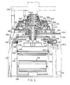
- Figure 1 is a longitudinal cross-sectional view of the main portion of a first embodiment of the invention;
- Figure 2 is a plan view showing a vibration dispersing means in the embodiment of Figure 1;
- Figure 3 is a longitudinal cross-sectional view of the main portion of a second embodiment of the invention;
- Figure 4 is a plan view showing the distance adjusting steel rings in the embodiment of Figure 3;
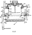
- Figure 5 is a longitudinal cross-sectional view of the main portion of a third embodiment of the invention;
- Figure 6 is a longitudinal cross-sectional view of the main portion of a fourth embodiment of the invention;
- As shown in Figure 1, a
machine frame 10 comprises, as in conventional machines three supportinglegs 11 and a supportingring 12 provided in the middle portion of theframe 10. It also comprises a supporting table 13 having ahub portion 14 withbearings 19 mounted in the centre thereof and abase plate 15 provided in the bottom of theframe 10. - A
needle cylinder 20 is fixed onto a rotatingdisc 21 which has a downwardly extendinghollow shaft 22 rotatably inserted in thebearings 19 housed within thehub 14. A rotatingwheel 24 is fixed at the lower end of saidshaft 22 bynuts 25 and a key. Avibration dispersing device 30 is provided below the supporting table 13 as shown in Figure 1 and Figure 2, in such a manner that one end is fixed on a supportingframe 16, which is separated from saidmachine frame 10 and provided for installing the motor M and driving means 80 therein. The other end of thedevice 30 is a ring shapefree end 31 fixed to the outer periphery of saidhub portion 14 by bolts. ` Aring gear 40 for driving said rotatingwheel 24 through a transmission means is slidably, rotatably mounted on a rail portion 121 of said supportingring 12. Thegear 40 meshes with a driving pinion 41 rotatably supported on adriving shaft 43 at themesh point 42 and is driven by the driving pinion 41 which is driven by the motor M mounted on saidframe 16 through a suitable transmission means 80. - At opposed locations on the inner side of said
gear 40, there are provided a pair oftransmission arms 45 having a pair ofradial grooves 44 on their upper surface and a pair of pin-shapedfree ends 46 on their lower ends. A pair ofupper transmission arms 26 is provided on opposite sides of the lower face of the rotatingwheel 24 and have their pin-shapedfree ends 27 radially slidably inserted into saidgrooves 44 but always contacting with the one side of wall of saidgrooves 44 in the rotating direction of thegear 40 so as to transmit the rotation of saidgear 40 to the rotatingwheel 24 as well as to accomplish a self centering alignment with respect to the centre of saidgear 40. - Beneath the
transmission arms 45 there is a knitted fabric take-updevice 5 provided for winding the knitted fabric into a roll. Said take-updevice 5 consists of a pair ofbrackets 51 having a pair ofradial grooves 52 on their upper ends corresponding saidtransmission arms 45 for engaging with saidpin ends 46. The downward pin-shapedfree ends 46 of saidtransmission arms 45 are radial slidably inserted into thegrooves 52 in the like manner as said pin ends 27 of thetransmission arms 26 so as to rotate said roller means 5. - The driving
shaft 43 extends upwardly and passes through saidvibration dispersing member 30 and supporting tables 13, 23 so as to drive an automatic yarn feeding device (not shown) and the dial means 6 (shown in dot lines) through suitable transmission gears (not shown). Saidshaft 43 is driven by the motor M mounted on the bottom of saidframe 16 via asuitable transmission gear 80. - In order to prevent the vibration of the
driving shaft 43 affecting said supporting table 13 provided with a cam set 28 thereon, thehole 17 on the supporting table 13, through which saidshaft 43 passes, is a little larger in diameter than theshaft 43 to provide a clearance. Only the holes provided on the supportingring 12 andvibration dispersing member 30 havebearings shaft 43. - Figures 3 and 4 show a second embodiment of the invention. In this embodiment, the
machine frame 10A consists of a plurality oflegs 11A, a supportingring 12A and supporting tables 13A, 23A similar to those in the first embodiment. Both the rotatingdisc 21A having aneedle cylinder 20A disposed thereon and the rotatingplate 67A having adial 60A disposed thereon are fixed on a commonhollow shaft 22A which is rotatably supported between thecentre hubs 14A of the upper supporting table 23A (shown in dot line) and the lower supporting table 13A by means ofbearings 19A. When saidhollow shaft 22A rotates, both the rotatingdisc 21A andplate 67A rotate together with saidshaft 22A. Upon the.plate 67A, acam device 68A with its lower surface against saiddial 60A is mounted on acam seat 69A which is secured onto the lower end of the downward extending central hub of the upper supporting table 23A. Surrounding saidneedle cylinder 20A there is acam device 28A mounted on a lower cam seat which is fixed onto said lower supporting table 13A. Between saidplate 67A and saiddisc 21A, there are an upper and a lower distance adjustingrings bars disc 21A and onto saidhollow shaft 22A respectively so as to support saidrings ring 63A is a circular ring and concentric with saidhollow shaft 22A, while said lower adjustingring 64A is a heart-shaped ring. A cutting knife 66A is provided between saidplate 67A and saiddisc 21A and extends vertically downward whereby the knitted cylindrical fabric is longitudinally cut into a flat one so as to be collected in a bundle form and led into thefabric inlet 65A opened on the side of saidhollow shaft 22A at the position opposite to said knife 66A and above saiddisc 21A. Avibration dispersing member 30A is provided below the table 13A with itsfree end 31A and root end fixed onto saidhub 14A and theframe 16A respectively as in the first embodiment. - To further clarify, as the arrows shown in Figure 3 and 4, the cylindrical knitted fabric is vertically cut at a position corresponding to the knife to become a flat one by said cutting knife 66A, and then collected at the cut end to form a bundle, and the bundle of fabric is led downward through said distance adjusting
rings ring 63A to saidfabric inlet 65A, finally the bundle-like fabric is led out from the lower opening of saidhollow shaft 22A and is spread to become a sheet-like fabric so as to be wound up by take-updevice 5A. - The gear driving means and transmission means below said
hollow shaft 22A are the same with the former embodiment, i.e. theshaft 22A is rotatably supported in thebearings 19A disposed in thehub portion 14A of the table 13A; affixed onto the lower end of saidshaft 22A is the rotatingwheel 24A, on the opposite sides of the periphery of which is a pair oftransmission arms 26A diametrically disposed. Aring gear 40A is also provided below said rotatingwheel 24A and meshes with a drivingpinion 41A rotatably mounted inside the groove of said supportingring 12A via adriving shaft 43A. A pair oftransmission arms 45A are disposed on the inside periphery of saidring gear 40A and consist of a pair ofradial grooves 44A on their upper ends for engaging with thepin ends 27A of saidarms 26A and a pair of pin shapefree ends 46A at their lower ends. Below thetransmission member 45A, there is the fabric take-updevice 5A provided with a pair ofbrackets 51A having a pair ofgrooves 52A on the upper ends for engaging with thepin ends 46A of saidarms 45A. The gear driving and the transmission means is so constructed, when thering gear 40A is driven to rotate along said supportingring 12A by saidpinion 41A, the rotatingdisc 21A with provision of theneedle cylinder 20A thereon and therotating plate 67A with provision of saiddial 60A thereon rotates steadily through thetransmission arms wheel 24A and saidhollow shaft 22A. - In this embodiment, except that both of the rotating
disc 21A and rotatingplate 67A are fixed onto acentral shaft 22A instead of the twocorresponding members 21 and 67 being fixed on two separate shafts as in the first embodiment, and that in order to enable the fabric to pass through the space between saiddisc 21A andplate 67A and to be led into the centre hole of saidshaft 22A, there are the provision of the cutting knife 66A, the distance adjustingrings fabric inlet 65A, all other elements are the same as the first embodiment. - Figure 5 shows a third embodiment of the invention, which is an application of the driving and transmission means of the first embodiment to a conventional single or double side type circular knitting machine. In this kind of machine, there is no provision of a
central shaft 22 and avibration dispersing device 30 like the first embodiment described above, but the application of the driving and transmission mechanism of this invention to said machine can also obtain a stable and even motion. Therefore the vibration or oscillation can be relatively reduced. - In the conventional circular knitting machine, the cylinder member 21 B is integrally connected to the ring gear 40B, but in this embodiment, the ring gear 40B is separated from said
cylinder 21 B. Said gear 40B is rotatably disposed on the supporting ring 12B of theframe 10B like the manner of the first embodiment and is driven by the drivingpinion 41 B provided in the supporting ring 12B. The cylinder member 21 B is provided with a pair oftransmission arms 26B extending downward and having a pair ofpins 27B formed at their lower end. Atransmission ring 47B, which has a pair ofradial grooves 44B provided on its upper surface for engaging with saidpins 27B and a pair oftransmission arms 45B extending downward therefrom with a pair ofpins 46B provided on the free ends for inserting into thegrooves 52B of thetransmission brackets 51B, is attached to the ring gear 40B rotatably mounted on the supporting ring 12B. A drivingpinion 41 B is fixed on the drivingshaft 43B to rotate together with it and meshes with the ring gear 40B at themesh point 42B. When the drivingpinion 41B rotates with theshaft 43B, the ring gear 40B is driven to rotate on the supporting ring 12B by thepinion 41B. Thus the rotation of the ring gear 40B is transmitted to the cylinder 21B and the fabric take-updevice 5B. The difference between this embodiment and the first embodiment is that the cylinder 21 B also functions as a rotating wheel, therefore, there is no separaterotating wheel 24 such as in the first embodiment. As regard to other parts and portions, they are structurally same as in a conventional machine, so they are omitted from the drawings and the description. - Figure 6 shows a fourth embodiment of this invention. In this embodiment, instead of the
ring gear 40 being mounted on the supporting ring as in the first embodiment, agear wheel 40C with abearing 46C in its centre is used and rotatably supported in the centre of thebase plate 15C at the bottom of themachine frame 10C. Thegear wheel 40C meshes with the drivingpinion 41C at themesh point 42C and is driven by the drivingpinion 41C. Arotating wheel 24C fixed to the lower end of thehollow shaft 22C is driven by thegear wheel 40C through a transmission member which consists of a pair of upper transmission arms 26C fixed on therotating wheel 24C and a pair of lower transmission arms 51 C fixed on thegear wheel 40C. These arms are connected to each other bypins 27C and grooves 52C at their connecting ends. Because the driving means consisting of a motor M, drivingpinion 41C andgear 40C are located on thebottom frame 15C, if the power is to be directly transmitted to the upper gear provided for driving the dial device and the automatic yarn feeding device, the transmission distance will be too long and the driving shaft also must be extended upward from the bottom of the frame and become ineffective from the point of dynamics. Therefore, therotating wheel 24C is formed as a gear wheel and meshes with apinion 70 fixed on theshaft 43C. Theshaft 43C functions as the extension of the drivingshaft 43 in the first embodiment to drive the dial device and yarn feeding device provided on the upper supporting table 23C of theframe 10C. - In another embodiment, the
gear 40C used in the fourth embodiment is omitted. To drive the rotating disc 21C, therotating gear wheel 24C, which is originally a driving gear now becomes a driven gear, and is directly driven by thepinion 70 which is originally a driven pinion and now becomes a driving pinion and is driven by the motor M through a suitable transmission device 80C. Thus both of the rotating disc 21 C provided the needle cylinder 20C thereon and the transmission arms 26C, 51 C for supporting the fabric take-updevice 5C are driven by thegear 24C. - The above description of various embodiments are most for the double knit type circular knitting machines. However the only difference between single knit type and double knit type is that the former comprises a needle cylinder and a dial device, while the latter comprises only a needle cylinder and no dial device and the related mechanism provided thereon. Therefore, this invention can be applied to both of single knit type and double knit type circular knitting machines.
- In this invention, because the mesh point of the gears is removed from near the needle cylinder to a much farther location, and the rotation of needle cylinder is stabilized by the rotating wheel and the self-centre-alignable transmission device, especially in the first and second embodiments, the rotating plate and disc supporting needle cylinders thereon have a central shaft supported in the centre of supporting tables, so that they are provided with steady support and also aligned on the same axis, enabling the knitting machine to diminish vibrations caused by the imbalance at the power input point, at the same time to disperse the vibration evenly to the needle points. The combined effects prevent the undesirable horizontal lines on the knitted fabrics, and upgrade quality and the value of the products.
Claims (8)
Priority Applications (3)
| Application Number | Priority Date | Filing Date | Title |
|---|---|---|---|
| EP81300764A EP0058790B1 (en) | 1981-02-24 | 1981-02-24 | Circular knitting machine |
| AT81300764T ATE17753T1 (en) | 1981-02-24 | 1981-02-24 | CIRCULAR KNITTING MACHINE. |
| DE8181300764T DE3173592D1 (en) | 1981-02-24 | 1981-02-24 | Circular knitting machine |
Applications Claiming Priority (1)
| Application Number | Priority Date | Filing Date | Title |
|---|---|---|---|
| EP81300764A EP0058790B1 (en) | 1981-02-24 | 1981-02-24 | Circular knitting machine |
Publications (2)
| Publication Number | Publication Date |
|---|---|
| EP0058790A1 EP0058790A1 (en) | 1982-09-01 |
| EP0058790B1 true EP0058790B1 (en) | 1986-01-29 |
Family
ID=8188223
Family Applications (1)
| Application Number | Title | Priority Date | Filing Date |
|---|---|---|---|
| EP81300764A Expired EP0058790B1 (en) | 1981-02-24 | 1981-02-24 | Circular knitting machine |
Country Status (3)
| Country | Link |
|---|---|
| EP (1) | EP0058790B1 (en) |
| AT (1) | ATE17753T1 (en) |
| DE (1) | DE3173592D1 (en) |
Cited By (1)
| Publication number | Priority date | Publication date | Assignee | Title |
|---|---|---|---|---|
| CN103710836A (en) * | 2013-12-26 | 2014-04-09 | 宁波裕人数控科技有限公司 | Machine head front-placed locating device for circular knitting machine |
Families Citing this family (6)
| Publication number | Priority date | Publication date | Assignee | Title |
|---|---|---|---|---|
| GB2305190B (en) * | 1995-04-28 | 1999-03-31 | Lin Chin Yung | A synchronous cloth-rolling apparatus of a knitting machine |
| CN109941802B (en) * | 2019-05-06 | 2024-01-30 | 常州纳捷机电科技有限公司 | Elastic cloth vibration feeding mechanism and method |
| CN112981689B (en) * | 2021-02-02 | 2025-04-25 | 泉州全能智控机械研究所有限公司 | Center-shaft-less driving mechanism of double-sided circular knitting machine and double-sided circular knitting machine |
| CN113174692B (en) * | 2021-05-26 | 2024-11-01 | 诸暨市尤工机械有限公司 | Vamp machine of easy maintenance adjustment |
| CN118957862B (en) * | 2024-10-15 | 2025-03-04 | 泉州恒毅机械有限公司 | Double-sided plush knitting machine |
| CN119265786A (en) * | 2024-11-07 | 2025-01-07 | 桐乡观华纺织有限公司 | Adjustable transmission mechanism for circular knitting machine |
Family Cites Families (5)
| Publication number | Priority date | Publication date | Assignee | Title |
|---|---|---|---|---|
| US3256714A (en) * | 1966-06-21 | Dial drive for knitting machines | ||
| FR1394455A (en) * | 1963-05-06 | 1965-04-02 | Singer Co | Device for driving the needle holder dial of a knitting machine and machine with application |
| US3222889A (en) * | 1963-05-06 | 1965-12-14 | Singer Co | Dial drive for knitting machines |
| GB1287645A (en) * | 1970-04-01 | 1972-09-06 | M L G Comber Ltd | Improvements in knitting machines |
| DE2316303A1 (en) * | 1973-03-31 | 1974-10-10 | Mayer & Cie Maschinenfabrik | Multi system circular knitting machine - with hollow needle cylinder cooperating with radially outer annular lock ring |
-
1981
- 1981-02-24 AT AT81300764T patent/ATE17753T1/en not_active IP Right Cessation
- 1981-02-24 DE DE8181300764T patent/DE3173592D1/en not_active Expired
- 1981-02-24 EP EP81300764A patent/EP0058790B1/en not_active Expired
Cited By (1)
| Publication number | Priority date | Publication date | Assignee | Title |
|---|---|---|---|---|
| CN103710836A (en) * | 2013-12-26 | 2014-04-09 | 宁波裕人数控科技有限公司 | Machine head front-placed locating device for circular knitting machine |
Also Published As
| Publication number | Publication date |
|---|---|
| EP0058790A1 (en) | 1982-09-01 |
| DE3173592D1 (en) | 1986-03-13 |
| ATE17753T1 (en) | 1986-02-15 |
Similar Documents
| Publication | Publication Date | Title |
|---|---|---|
| EP0058790A1 (en) | Circular knitting machine | |
| EP0652314B1 (en) | Method and apparatus for adjusting the stitch length on a circular knitting machine | |
| GB2181163A (en) | High speed tufting machine | |
| US6131417A (en) | Circular knitting machine with an exchangeable needle cylinder | |
| US2823530A (en) | Intermediate connecting and supporting means for rotational sectional beams and the like | |
| CN108360140B (en) | Spacer yarn constant tension control mechanism of ultra-large gauge warp knitting machine | |
| US3222889A (en) | Dial drive for knitting machines | |
| US4512373A (en) | Feeding and guiding means for triaxial fabric forming machine | |
| CN108716592A (en) | A kind of weaving loom damping base easy to remove | |
| US4261187A (en) | Oscillation damping and counterpoising circular knitting machine | |
| US4228563A (en) | Drive apparatus of a can for depositing textile fibre slivers | |
| US3491556A (en) | Dial support for a cylinder and dial knitting machine | |
| KR950003316Y1 (en) | Circular knitting machine | |
| US5141170A (en) | Friction thread feed device | |
| KR850000292B1 (en) | Circular knitting machine | |
| US4222221A (en) | Winding machine with multitwist spindle | |
| US1629366A (en) | Ring-spinning frame | |
| US3181312A (en) | Knitting machine | |
| US2030495A (en) | Embroiering machine | |
| CN210621099U (en) | Tricot machine yarn dividing mechanism convenient to adjustment yarn angle | |
| US4580418A (en) | Oscillation damping and counterpoising circular knitting machine | |
| US3076616A (en) | Warp beam mounting for knitting machines | |
| US885304A (en) | Dial knitting-machine. | |
| SU544719A1 (en) | Support ring ring textile machines | |
| GB523232A (en) | Improvements in or relating to circular knitting machines |
Legal Events
| Date | Code | Title | Description |
|---|---|---|---|
| PUAI | Public reference made under article 153(3) epc to a published international application that has entered the european phase |
Free format text: ORIGINAL CODE: 0009012 |
|
| AK | Designated contracting states |
Designated state(s): AT BE CH DE FR GB IT NL SE |
|
| 17P | Request for examination filed |
Effective date: 19830217 |
|
| GRAA | (expected) grant |
Free format text: ORIGINAL CODE: 0009210 |
|
| AK | Designated contracting states |
Designated state(s): AT BE CH DE FR GB IT LI NL SE |
|
| PG25 | Lapsed in a contracting state [announced via postgrant information from national office to epo] |
Ref country code: NL Effective date: 19860129 Ref country code: LI Effective date: 19860129 Ref country code: IT Free format text: LAPSE BECAUSE OF FAILURE TO SUBMIT A TRANSLATION OF THE DESCRIPTION OR TO PAY THE FEE WITHIN THE PRESCRIBED TIME-LIMIT;WARNING: LAPSES OF ITALIAN PATENTS WITH EFFECTIVE DATE BEFORE 2007 MAY HAVE OCCURRED AT ANY TIME BEFORE 2007. THE CORRECT EFFECTIVE DATE MAY BE DIFFERENT FROM THE ONE RECORDED. Effective date: 19860129 Ref country code: FR Free format text: THE PATENT HAS BEEN ANNULLED BY A DECISION OF A NATIONAL AUTHORITY Effective date: 19860129 Ref country code: CH Effective date: 19860129 Ref country code: BE Effective date: 19860129 Ref country code: AT Effective date: 19860129 |
|
| REF | Corresponds to: |
Ref document number: 17753 Country of ref document: AT Date of ref document: 19860215 Kind code of ref document: T |
|
| PG25 | Lapsed in a contracting state [announced via postgrant information from national office to epo] |
Ref country code: SE Effective date: 19860131 |
|
| REF | Corresponds to: |
Ref document number: 3173592 Country of ref document: DE Date of ref document: 19860313 |
|
| REG | Reference to a national code |
Ref country code: CH Ref legal event code: PL |
|
| EN | Fr: translation not filed | ||
| NLV1 | Nl: lapsed or annulled due to failure to fulfill the requirements of art. 29p and 29m of the patents act | ||
| PLBE | No opposition filed within time limit |
Free format text: ORIGINAL CODE: 0009261 |
|
| STAA | Information on the status of an ep patent application or granted ep patent |
Free format text: STATUS: NO OPPOSITION FILED WITHIN TIME LIMIT |
|
| 26N | No opposition filed | ||
| PG25 | Lapsed in a contracting state [announced via postgrant information from national office to epo] |
Ref country code: GB Effective date: 19890224 |
|
| GBPC | Gb: european patent ceased through non-payment of renewal fee | ||
| PG25 | Lapsed in a contracting state [announced via postgrant information from national office to epo] |
Ref country code: DE Effective date: 19891101 |