EP0058754A2 - Arrangement for injecting digital signals into a line system - Google Patents
Arrangement for injecting digital signals into a line system Download PDFInfo
- Publication number
- EP0058754A2 EP0058754A2 EP81108638A EP81108638A EP0058754A2 EP 0058754 A2 EP0058754 A2 EP 0058754A2 EP 81108638 A EP81108638 A EP 81108638A EP 81108638 A EP81108638 A EP 81108638A EP 0058754 A2 EP0058754 A2 EP 0058754A2
- Authority
- EP
- European Patent Office
- Prior art keywords
- digital signals
- line system
- output
- transformer
- frequency
- Prior art date
- Legal status (The legal status is an assumption and is not a legal conclusion. Google has not performed a legal analysis and makes no representation as to the accuracy of the status listed.)
- Granted
Links
Images
Classifications
-
- H—ELECTRICITY
- H04—ELECTRIC COMMUNICATION TECHNIQUE
- H04B—TRANSMISSION
- H04B3/00—Line transmission systems
- H04B3/54—Systems for transmission via power distribution lines
- H04B3/56—Circuits for coupling, blocking, or by-passing of signals
-
- H—ELECTRICITY
- H04—ELECTRIC COMMUNICATION TECHNIQUE
- H04L—TRANSMISSION OF DIGITAL INFORMATION, e.g. TELEGRAPHIC COMMUNICATION
- H04L27/00—Modulated-carrier systems
- H04L27/02—Amplitude-modulated carrier systems, e.g. using on-off keying; Single sideband or vestigial sideband modulation
- H04L27/04—Modulator circuits; Transmitter circuits
-
- H—ELECTRICITY
- H04—ELECTRIC COMMUNICATION TECHNIQUE
- H04B—TRANSMISSION
- H04B2203/00—Indexing scheme relating to line transmission systems
- H04B2203/54—Aspects of powerline communications not already covered by H04B3/54 and its subgroups
- H04B2203/5404—Methods of transmitting or receiving signals via power distribution lines
- H04B2203/5416—Methods of transmitting or receiving signals via power distribution lines by adding signals to the wave form of the power source
-
- H—ELECTRICITY
- H04—ELECTRIC COMMUNICATION TECHNIQUE
- H04B—TRANSMISSION
- H04B2203/00—Indexing scheme relating to line transmission systems
- H04B2203/54—Aspects of powerline communications not already covered by H04B3/54 and its subgroups
- H04B2203/5429—Applications for powerline communications
- H04B2203/5458—Monitor sensor; Alarm systems
-
- H—ELECTRICITY
- H04—ELECTRIC COMMUNICATION TECHNIQUE
- H04B—TRANSMISSION
- H04B2203/00—Indexing scheme relating to line transmission systems
- H04B2203/54—Aspects of powerline communications not already covered by H04B3/54 and its subgroups
- H04B2203/5462—Systems for power line communications
- H04B2203/5483—Systems for power line communications using coupling circuits
Landscapes
- Engineering & Computer Science (AREA)
- Computer Networks & Wireless Communication (AREA)
- Signal Processing (AREA)
- Power Engineering (AREA)
- Dc Digital Transmission (AREA)
- Digital Transmission Methods That Use Modulated Carrier Waves (AREA)
- Cable Transmission Systems, Equalization Of Radio And Reduction Of Echo (AREA)
Abstract
Description
Die Erfindung betrifft eine Einrichtung zur Einspeisung von digitalen Signalen in ein Leitungssystem in Form einer amplitudenmodulierten Wechselspannung.The invention relates to a device for feeding digital signals into a line system in the form of an amplitude-modulated AC voltage.
Derartige Einrichtungen finden beispielsweise im Rahmen von Rundsteuersystemen Anwendung. Hierbei werden die ein Impulstelegramm darstellenden digitalen Signale mit einer tonfrequenten Wechselspannung als Träger in das öffentliche Stromversorgungsnetz als Leitungssystem eingespeist. Zur Amplitudenmodulation der tonfrequenten Wechselspannung zwischen einem festen Amplitudenwert und Amplitudenwert Null dienen aufwendige Wechselrichter, vorzugsweise Impulswechselrichter. Dieser Aufwand ist bei der Rundsteuertechnik gerechtfertigt, da die digitalen Signale eine erhebliche Reichweite besitzen müssen, um weit auseinanderliegende Rundsteuerempfänger zu erreichen. Für kleine Übertragungsreichweiten ist jedoch ein derartiger Aufwand nicht gerechtfertigt.Devices of this type are used, for example, in the context of ripple control systems. The digital signals representing a pulse telegram are fed into the public power supply network as a line system with a sound-frequency alternating voltage as a carrier. Elaborate inverters, preferably pulse inverters, are used for amplitude modulation of the audio frequency alternating voltage between a fixed amplitude value and zero amplitude value. This expense is justified in ripple control technology, since the digital signals must have a considerable range in order to reach ripple control receivers that are far apart. Such an effort is not justified for small transmission ranges.
Der Erfindung liegt die Aufgabe zugrunde, eine Einrichtung der eingangs genannten Art anzugeben, die bei Beschränkung auf eine kleine Reichweite mit geringem Aufwand kostengünstig herstellbar ist. Unter dem Begriff "kleine Reichweite" wird in diesem Zusammenhang eine Reichweite verstanden, die das Ansprechen von Empfängern innerhalb eines Gebäudes oder innerhalb mehrerer benachbarter Gebäude gestattet.The invention has for its object to provide a device of the type mentioned, which can be produced inexpensively with little effort when limited to a small range. In this context, the term “short range” is understood to mean a range that allows receivers to be addressed within a building or within several neighboring buildings.
Die Aufgabe wird erfindungsgemäß dadurch gelöst, daß die digitalen Signale an den einen Eingang eines Exclusiv-ODER-Gatters geführt sind, dessen zweiter Eingang an den Ausgang eines Frequenzgenerators angeschlossen ist, dessen periodisches Ausgangssignal unipolar und von höherer Frequenz ist als die maximale Wiederholungsfrequenz der digitalen Signale, daß die Primärwicklung eines Übertragers einerseits an den Ausgang des Frequenzgenerators, andererseits an den Ausgang des Exclusiv-ODER-Gatters angeschlossen ist und daß die Sekundärwicklung des Übertragers an zwei Leitungen des Leitungssystems angeschlossen ist.The object is achieved in that the digital signals are led to one input of an exclusive-OR gate, the second input of which is connected to the output of a frequency generator, the periodic output signal of which is unipolar and of a higher frequency than the maximum repetition frequency of the digital signals that the primary winding of a transmitter is on the one hand the output of the Fre q uenzgenerators, on the other hand connected to the output of the exclusive-OR gate and in that the secondary winding of the transformer on two lines of the line system is connected.
Damit kann die erfindungsgemäße Einrichtung aus kostengünstigen handelsüblichen Bauelementen aufgebaut werden. Durch den Frequenzgenerator wird die Trägerfrequenz für die digitalen Signale geliefert. Die Höhe der Trägerfrequenz richtet sich nach den Gegebenheiten des Leitungssystems sowie nach Frequenz- und Formerfordernissen der digitalen Signale. Die Form der Ausgangssignale des Frequenzgenerators ist in weiten Grenzen beliebig, sie können also beispielsweise sinusförmig, dreieckförmig, rechteckförmig oder trapezförmig sein. Wesentlich ist, daß diese Ausgangssignale unipolar sind, d.h., daß sie nur auf einer Seite der Spannungsnullinie liegen und vorzugsweise zwischen einen positiven Spannungswert und dem Spannungswert Null oszillieren.The device according to the invention can thus be constructed from inexpensive commercially available components. The carrier frequency for the digital signals is supplied by the frequency generator. The level of the carrier frequency depends on the conditions of the line system and the frequency and shape requirements of the digital signals. The shape of the output signals of the frequency generator is arbitrary within wide limits, so they can be, for example, sinusoidal, triangular, rectangular or trapezoidal. It is essential that these output signals are unipolar, i.e. that they are only on one side of the voltage zero line and preferably oscillate between a positive voltage value and the voltage value zero.
In einer bevorzugten Ausführungsform ist als Übertrager ein Übertrager mit einem Ferritkern eingesetzt. Ein solcher Übertrager gestattet eine relativ verzerrungsfreie Übertragung der Eingangssignale.In a preferred embodiment, a transformer with a ferrite core is used as the transformer. Such a transmitter allows a relatively distortion-free transmission of the input signals.
Wenn als Leitungssystem die netzspannungsführenden Leitungen dienen, ist es vorteilhaft, wenn die Sekundärwicklung des Übertragers über mindestens einen Kondensator an das Leitungssystem angeschlossen ist. Durch geeignete Dimensionierung des Kondensators wird einerseits eine hohe Durchlässigkeit für die amplitudenmodulierte Wechselspannung, andererseits eine gute Sperrwirkung gegen Rückwirkungen durch die Netzfrequenz erreicht.If the mains voltage-carrying lines serve as the line system, it is advantageous if the secondary winding of the transformer is connected to the line system via at least one capacitor. By suitable dimensioning of the capacitor, on the one hand a high permeability for the amplitude-modulated alternating voltage, on the other hand a good blocking effect against effects caused by the mains frequency.
Es ist vorteilhaft, wenn ein Frequenzgenerator eingesetzt ist, dessen Ausgangssignal ein aus Rechteckimpulsen bestehender Impulszug ist. Als solcher Frequenzgenerator kann beispielsweise als besonders kostengünstiges Funktionselement ein astabiler Multiyibrator eingesetzt sein.It is advantageous if a frequency generator is used, the output signal of which is a pulse train consisting of rectangular pulses. An astable multi-vibrator can be used as such a frequency generator, for example, as a particularly inexpensive functional element.
Die Erfindung wird im folgenden anhand eines Ausführungsbeispiels in den Fig., 1 und 2 näher erläutert. Dabei zeigt:
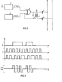
- Fig. 1 ein Schaltbild der erfindungsgemäßen Einrichtung und
- Fig. 2 Impulsdiagramme zur Erläuterung der Arbeitsweise der in Fig. 1 dargestellten Einrichtung.
- Fig. 1 is a circuit diagram of the device according to the invention and
- Fig. 2 pulse diagrams to explain the operation of the device shown in Fig. 1.
In Fig. 1 ist mit dem Bezugszeichen 1 ein Codierer belegt, der ausgangsseitig als digitales Signal eine als Impulszug kodierte Information liefert, die an seiner Eingangsklemme 2 beispielsweise als Analogsignal ansteht. Solche Analogsignale können beispielsweise an eine andere Stelle eines Gebäudes zu übertrangende Temperaturwerte eines Heizungssystems, eine BCD-kodierte Uhrzeit oder einfach Ein- bzw. Ausschaltbefehle für in einem Haus verteilte Beleuchtungskörper sein. Das Ausgangssignal des Codierers 1 ist an den Eingang A eines Exclusiv-ODER-Gatters 3 geführt.In Fig. 1, the reference numeral 1 denotes an encoder which on the output side supplies as a digital signal information coded as a pulse train which is present at its input terminal 2, for example as an analog signal. Such analog signals can be, for example, temperature values of a heating system to be transmitted to another location in a building, a BCD-coded time of day or simply switch-on or switch-off commands for lighting fixtures distributed in a house. The output signal of encoder 1 is fed to input A of an exclusive OR gate 3.
Der zweite Eingang B des Exclusiv-ODER-Gatters 3 ist mit dem Ausgang eines Frequenzgenerators 4 verbunden. Der Frequenzgenerator 4 liefert ein periodisches Ausgangssignal, dessen Frequenz - wie bei der Amplitudenmodulation üblich - erheblich höher sein muß als die maximale Wiederholungsfrequenz der digitalen Signale des Codierers 1, da das Ausgangssignal des Frequenzgenerators 4 die Trägerfrequenz für die Übertragung der digitalen Signale darstellt. Im Ausführungsbeispiel ist der Frequenzgenerator 4 als Rechteckgenerator ausgebildet, dessen Ausgangssignal eine positive Rechteckspannung ohne weiteren Gleichspannungsanteil darstelllt.The second input B of the exclusive OR gate 3 is connected to the output of a frequency generator 4. The frequency generator 4 supplies a periodic output signal, the frequency of which - as is customary in the case of amplitude modulation - must be considerably higher than the maximum repetition frequency of the digital signals of the encoder 1, since the output signal of the frequency generator 4 represents the carrier frequency for the transmission of the digital signals. In the exemplary embodiment, the frequency generator 4 is designed as a square-wave generator, the output signal of which represents a positive square-wave voltage without a further DC voltage component.
Die Primärwicklung 5 eines Übertragers 6 ist einerseits an den Ausgang C des Exclusiv-ODER-Gatters 3, andererseits an den Ausgang des Frequenzgenerators 4 angeschlossen. An dieser Primärwicklung 5 steht somit die Spannung U1 an, die der Differenz der momentanen Spannungswerte der am Eingang B bzw. dem Ausgang C des Exclusiv-ODER-Gatters 3 anstehenden Signale entspricht.The primary winding 5 of a transformer 6 is connected on the one hand to the output C of the exclusive OR gate 3 and on the other hand to the output of the frequency generator 4. The voltage U1, which corresponds to the difference between the instantaneous voltage values of the signals present at input B and output C of the exclusive OR gate 3, is thus present at this primary winding 5.
Die Sekundärwicklung 7 des im Ausführungsbeispiel mit einem Ferritkern ausgestatteten Übertragers 6 ist einerseits über den Kondensator 8 mit dem Phasenleiter R und andererseits über den Kondensator 9 mit dem Nulleiter, der als Leitungssystem dienenden Netzleitungen innerhalb einer Wohnung oder eines Gebäudes verbunden. Die Kondensatoren 8 und 9 sperren den Rückfluß von netzfrequenten Signalen in den Übertrager 6, lassen jedoch andererseits aufgrund ihrer Dimensionierung die ins Leitungssystem einzuspeisenden Signale von gegenüber der Netzfrequenz erheblich höherer Frequenz in das Leitungssystem zu.The secondary winding 7 of the transformer 6, which in the exemplary embodiment is equipped with a ferrite core, is connected on the one hand via the capacitor 8 to the phase conductor R and, on the other hand, via the
In Fig. 2 ist in der ersten Zeile das die zu übertragende Information beinhaltende codierte Signal am Eingang A des Exclusiv-ODER-Gatters 3 dargestellt. In der darunter liegenden zweiten Zeile ist das unipolare periodische Ausgangssignal des Frequenzgenerators 4 dargestellt, das am Eingang B des Exclusiv-ODER-Gatters ansteht. Dieses rechteckförmige Signal weist ein Tastverhältnis von 1:1 auf und schwankt zwischen den beiden festen Pegeln L und Null. In -derr dritten Zeile der Fig. 2 ist das am Ausgang C des Exclusiv-ODER-Gatters zustande gekommene Signal darstellt. In der vierten und letzten Zeile der Fig. 2 ist schließlich das an der Primärwicklung 5 des Übertragers 6 anstehende Signal U1 = B - C dargestellt. Liegt der Eingang A des Exclusiv-ODER-Gatters 3 auf dem Pegel Null, dann erscheint am Ausgang C des Exclusiv-ODER-Gatters 3 zu jedem Zeitpunkt ein Signal übereinstimmender Amplituden- und Phasenlage, so daß die Spannung U1 an der Primärwicklung 5 stets den Wert Null aufweist. Liegt dagegen der Eingang A des Exclusiv-ODER-Gatters 3 auf dem Signalpegel L, dann sind die Signale am Eingang B und am Ausgang C des Exclusiv-ODER-Gatters 3 antivalent. Damit kommt jeweils für die Zeitspanne, für die am Eingang A der Signalpegel L vorhanden ist, an der Primärwicklung 5 des Übertragers 6 eine um die Nullinie oszillierende Rechteckwechselspannung ohne Gleichspannungsanteil zustande, die über die Sekundärwicklung 7 des Übertragers 6 in das Leitungssystem R-0 eingespeist wird. Jeweils für die Dauer, die das Signal am Eingang A auf L-Pegel ist, entsteht damit eine Rechteckwechselspannung zwischen den Spannungspegeln +L und -L, wohingegen in den Zeitspannen, in denen der Signalpegel am Eingang A den Wert 0 aufweist, die Spannung U1 einen konstanten Wert auf dem Pegel Null aufweist.2, the coded signal at the input A of the exclusive OR gate 3, which contains the information to be transmitted, is shown in the first line. The second line below shows the unipolar periodic output signal of the frequency generator 4, which is present at the input B of the exclusive OR gate. This rectangular signal has a duty cycle of 1: 1 and fluctuates between the two fixed levels L and zero. In the third line of FIG. 2 is the signal that is generated at output C of the exclusive OR gate represents. Finally, the fourth and last line of FIG. 2 shows the signal U1 = BC present at the primary winding 5 of the transformer 6. If the input A of the exclusive OR gate 3 is at the zero level, then a signal of matching amplitude and phase position appears at the output C of the exclusive OR gate 3, so that the voltage U1 on the primary winding 5 always Value is zero. If, however, input A of exclusive OR gate 3 is at signal level L, then the signals at input B and output C of exclusive OR gate 3 are equivalent. For the period of time for which the signal level L is present at input A, a square-wave alternating voltage without DC component oscillating around the zero line is produced at the primary winding 5 of the transformer 6 and is fed into the line system R-0 via the secondary winding 7 of the transformer 6 becomes. For the duration that the signal at input A is at the L level, a square-wave alternating voltage arises between the voltage levels + L and -L, whereas in the periods in which the signal level at input A has the value 0, the voltage U1 has a constant value at zero level.
Damit ist durch die erfindungsgemäße Einrichtung die Einspeisung von in Form digitaler Signale kodierter Informationen mit kleiner Leistung zur Übertragung über kurze Entfernungen mit geringem Aufwand ermöglicht.This enables the device according to the invention to feed information coded in the form of digital signals with low power for transmission over short distances with little effort.
Claims (4)
Applications Claiming Priority (2)
| Application Number | Priority Date | Filing Date | Title |
|---|---|---|---|
| DE19813106669 DE3106669A1 (en) | 1981-02-23 | 1981-02-23 | DEVICE FOR INPUTING DIGITAL SIGNALS INTO A LINE SYSTEM |
| DE3106669 | 1981-02-23 |
Publications (3)
| Publication Number | Publication Date |
|---|---|
| EP0058754A2 true EP0058754A2 (en) | 1982-09-01 |
| EP0058754A3 EP0058754A3 (en) | 1983-08-17 |
| EP0058754B1 EP0058754B1 (en) | 1985-06-26 |
Family
ID=6125524
Family Applications (1)
| Application Number | Title | Priority Date | Filing Date |
|---|---|---|---|
| EP81108638A Expired EP0058754B1 (en) | 1981-02-23 | 1981-10-21 | Arrangement for injecting digital signals into a line system |
Country Status (4)
| Country | Link |
|---|---|
| EP (1) | EP0058754B1 (en) |
| JP (1) | JPS57154963A (en) |
| DE (2) | DE3106669A1 (en) |
| ES (1) | ES509797A0 (en) |
Cited By (4)
| Publication number | Priority date | Publication date | Assignee | Title |
|---|---|---|---|---|
| EP0156557A2 (en) * | 1984-03-06 | 1985-10-02 | Controlonics Corporation | Transceiver for multi-drop local area networks |
| FR2567341A1 (en) * | 1984-07-03 | 1986-01-10 | Charbonnages De France | METHOD AND EQUIPMENT FOR TRANSFERRING SIGNALS RELATING TO AN ELECTRIC MACHINE PROVIDED WITH A THREE-PHASE POWER CABLE |
| WO2001069776A1 (en) * | 2000-03-14 | 2001-09-20 | Gemplus | Amplitude modulation device, in particular for contact-free reader, and device therefor |
| FR2891070A1 (en) * | 2005-09-16 | 2007-03-23 | Siemens Vdo Automotive Sas | METHOD FOR CALIBRATING AN ELECTRONIC SYSTEM INCORPORATING A BUILT-UP COMPUTING UNIT |
Families Citing this family (3)
| Publication number | Priority date | Publication date | Assignee | Title |
|---|---|---|---|---|
| US4794620A (en) * | 1984-07-06 | 1988-12-27 | International Anasazi, Inc. | Radio frequency modem and method |
| JPS63234652A (en) * | 1987-03-23 | 1988-09-29 | Fujitsu Ltd | Alternating signal generating circuit |
| DE29701412U1 (en) * | 1997-01-28 | 1998-05-28 | Zumtobel Licht | Device for transmitting information via power supply lines |
Citations (4)
| Publication number | Priority date | Publication date | Assignee | Title |
|---|---|---|---|---|
| US2599675A (en) * | 1950-12-14 | 1952-06-10 | Rca Corp | Tone keyer |
| US3846705A (en) * | 1973-08-16 | 1974-11-05 | Sperry Rand Corp | Pulse amplitude modulated signal generator |
| US4092599A (en) * | 1976-11-26 | 1978-05-30 | Werner Yee | Annunciator communication system |
| DE2825240A1 (en) * | 1978-06-08 | 1979-12-13 | Siemens Ag | ROTARY CONTROL SYSTEM |
-
1981
- 1981-02-23 DE DE19813106669 patent/DE3106669A1/en not_active Withdrawn
- 1981-10-21 EP EP81108638A patent/EP0058754B1/en not_active Expired
- 1981-10-21 DE DE8181108638T patent/DE3171137D1/en not_active Expired
-
1982
- 1982-02-05 JP JP57017382A patent/JPS57154963A/en active Pending
- 1982-02-22 ES ES509797A patent/ES509797A0/en active Granted
Patent Citations (4)
| Publication number | Priority date | Publication date | Assignee | Title |
|---|---|---|---|---|
| US2599675A (en) * | 1950-12-14 | 1952-06-10 | Rca Corp | Tone keyer |
| US3846705A (en) * | 1973-08-16 | 1974-11-05 | Sperry Rand Corp | Pulse amplitude modulated signal generator |
| US4092599A (en) * | 1976-11-26 | 1978-05-30 | Werner Yee | Annunciator communication system |
| DE2825240A1 (en) * | 1978-06-08 | 1979-12-13 | Siemens Ag | ROTARY CONTROL SYSTEM |
Cited By (9)
| Publication number | Priority date | Publication date | Assignee | Title |
|---|---|---|---|---|
| EP0156557A2 (en) * | 1984-03-06 | 1985-10-02 | Controlonics Corporation | Transceiver for multi-drop local area networks |
| EP0156557A3 (en) * | 1984-03-06 | 1987-07-15 | Controlonics Corporation | Transceiver for multi-drop local area networks |
| FR2567341A1 (en) * | 1984-07-03 | 1986-01-10 | Charbonnages De France | METHOD AND EQUIPMENT FOR TRANSFERRING SIGNALS RELATING TO AN ELECTRIC MACHINE PROVIDED WITH A THREE-PHASE POWER CABLE |
| EP0171302A1 (en) * | 1984-07-03 | 1986-02-12 | Etablissement public dit: CHARBONNAGES DE FRANCE | Method and apparatus for transmitting signals concerning an electric machine provided with a triple phase feeding cable |
| AU583522B2 (en) * | 1984-07-03 | 1989-05-04 | Charbonnages De France | Signal transfer method and equipment for electric machine equipped with three-phase power supply cable |
| US4862157A (en) * | 1984-07-03 | 1989-08-29 | Charbonnages De France | Signal transfer method and equipment for electric machine equipped with three-phase power supply cable |
| WO2001069776A1 (en) * | 2000-03-14 | 2001-09-20 | Gemplus | Amplitude modulation device, in particular for contact-free reader, and device therefor |
| FR2806563A1 (en) * | 2000-03-14 | 2001-09-21 | Gemplus Card Int | AMPLITUDE MODULATION METHOD, ESPECIALLY FOR A CONTACTLESS READER, AND IMPLEMENTATION DEVICE |
| FR2891070A1 (en) * | 2005-09-16 | 2007-03-23 | Siemens Vdo Automotive Sas | METHOD FOR CALIBRATING AN ELECTRONIC SYSTEM INCORPORATING A BUILT-UP COMPUTING UNIT |
Also Published As
| Publication number | Publication date |
|---|---|
| ES8303857A1 (en) | 1983-02-01 |
| JPS57154963A (en) | 1982-09-24 |
| DE3106669A1 (en) | 1982-09-09 |
| DE3171137D1 (en) | 1985-08-01 |
| EP0058754A3 (en) | 1983-08-17 |
| EP0058754B1 (en) | 1985-06-26 |
| ES509797A0 (en) | 1983-02-01 |
Similar Documents
| Publication | Publication Date | Title |
|---|---|---|
| EP0223315A2 (en) | Circuit arrangement for producing a DC voltage from an AC input voltage | |
| DE2932068C2 (en) | Circuit arrangement for continuously generating a ringing alternating current signal of predetermined frequency and amplitude | |
| DE2644767C3 (en) | Circuit arrangement for a ripple control receiver | |
| EP0058754B1 (en) | Arrangement for injecting digital signals into a line system | |
| DE2922219C3 (en) | Electronic sensor on / off switch | |
| DE2456344B2 (en) | Audio frequency ripple control system | |
| DE2633876A1 (en) | CIRCUIT ARRANGEMENT FOR GENERATING A REGULATED OUTPUT VOLTAGE FROM AN EQUAL INPUT VOLTAGE | |
| EP0451445A2 (en) | Contactless inductive transmission method of electrical energy and/or signals and contactless inductive transmission device | |
| DE2903860C2 (en) | Device for direct current supply to a consumer and for the simultaneous transmission of information via a pair of wires | |
| EP0171470B1 (en) | Feeding device for transmitters and receivers of a signal-transmission system | |
| DE2807916B2 (en) | Wake-up signal generator for use in a subscriber connection circuit | |
| AT401210B (en) | CIRCUIT ARRANGEMENT FOR TRANSMITTING SMALL, LOW-ENERGY AND LARGE, MORE ENERGY-SIGNAL SIGNALS | |
| DE2228008C3 (en) | Method and device for generating a transmission signal with a transmission frequency in a rigid relationship to the network frequency of the power supply network and application of this method | |
| DE2130916B2 (en) | Transmission circuit for digital signals | |
| DE1275637B (en) | Multi-channel modulation signal transmission system | |
| EP0089641B1 (en) | Remote control receiver, especially for the control of electrical devices | |
| DE2254009A1 (en) | ENERGY SUPPLY CIRCUIT | |
| DE2718999A1 (en) | VOLTAGE OR CURRENT REGULATED VOLTAGE CONVERTER | |
| DE2902443A1 (en) | ELECTRIC AC SWITCH, ESPECIALLY FOR HOME INSTALLATIONS | |
| EP0319104A2 (en) | Square wave generator | |
| DE3600170A1 (en) | INDUCTION HEATER | |
| DE859032C (en) | Circuit for generating current surges with the help of a polarized relay | |
| DE3533798A1 (en) | Isolating transformer | |
| DE112022002720T5 (en) | COMMUNICATION DEVICE, CORRESPONDING SYSTEM AND METHOD | |
| DE1413496C (en) | Circuit arrangement for converting a direct voltage into an alternating voltage of any curve shape and variable frequency |
Legal Events
| Date | Code | Title | Description |
|---|---|---|---|
| PUAI | Public reference made under article 153(3) epc to a published international application that has entered the european phase |
Free format text: ORIGINAL CODE: 0009012 |
|
| 17P | Request for examination filed |
Effective date: 19811021 |
|
| AK | Designated contracting states |
Designated state(s): CH DE FR GB IT |
|
| PUAL | Search report despatched |
Free format text: ORIGINAL CODE: 0009013 |
|
| AK | Designated contracting states |
Designated state(s): CH DE FR GB IT LI |
|
| ITF | It: translation for a ep patent filed |
Owner name: STUDIO JAUMANN |
|
| GRAA | (expected) grant |
Free format text: ORIGINAL CODE: 0009210 |
|
| AK | Designated contracting states |
Designated state(s): CH DE FR GB IT LI |
|
| REF | Corresponds to: |
Ref document number: 3171137 Country of ref document: DE Date of ref document: 19850801 |
|
| ET | Fr: translation filed | ||
| PLBE | No opposition filed within time limit |
Free format text: ORIGINAL CODE: 0009261 |
|
| STAA | Information on the status of an ep patent application or granted ep patent |
Free format text: STATUS: NO OPPOSITION FILED WITHIN TIME LIMIT |
|
| 26N | No opposition filed | ||
| PG25 | Lapsed in a contracting state [announced via postgrant information from national office to epo] |
Ref country code: LI Effective date: 19881031 Ref country code: CH Effective date: 19881031 |
|
| REG | Reference to a national code |
Ref country code: CH Ref legal event code: PL |
|
| PG25 | Lapsed in a contracting state [announced via postgrant information from national office to epo] |
Ref country code: DE Effective date: 19890701 |
|
| PG25 | Lapsed in a contracting state [announced via postgrant information from national office to epo] |
Ref country code: GB Effective date: 19891021 |
|
| GBPC | Gb: european patent ceased through non-payment of renewal fee | ||
| PG25 | Lapsed in a contracting state [announced via postgrant information from national office to epo] |
Ref country code: FR Effective date: 19900629 |
|
| REG | Reference to a national code |
Ref country code: FR Ref legal event code: ST |