EP0058655B1 - A method and mould core for casting concrete elements - Google Patents
A method and mould core for casting concrete elements Download PDFInfo
- Publication number
- EP0058655B1 EP0058655B1 EP82850024A EP82850024A EP0058655B1 EP 0058655 B1 EP0058655 B1 EP 0058655B1 EP 82850024 A EP82850024 A EP 82850024A EP 82850024 A EP82850024 A EP 82850024A EP 0058655 B1 EP0058655 B1 EP 0058655B1
- Authority
- EP
- European Patent Office
- Prior art keywords
- core
- mould
- parts
- mould core
- ram
- Prior art date
- Legal status (The legal status is an assumption and is not a legal conclusion. Google has not performed a legal analysis and makes no representation as to the accuracy of the status listed.)
- Expired
Links
- 238000000034 method Methods 0.000 title claims description 14
- 238000005266 casting Methods 0.000 title claims description 13
- 230000004913 activation Effects 0.000 claims 1
- 229910000831 Steel Inorganic materials 0.000 description 3
- 239000010959 steel Substances 0.000 description 3
- 238000010168 coupling process Methods 0.000 description 2
- 238000005859 coupling reaction Methods 0.000 description 2
- 238000000465 moulding Methods 0.000 description 2
- 230000008878 coupling Effects 0.000 description 1
- 238000010586 diagram Methods 0.000 description 1
- 238000006073 displacement reaction Methods 0.000 description 1
- 230000005484 gravity Effects 0.000 description 1
- 238000004519 manufacturing process Methods 0.000 description 1
Images
Classifications
-
- B—PERFORMING OPERATIONS; TRANSPORTING
- B28—WORKING CEMENT, CLAY, OR STONE
- B28B—SHAPING CLAY OR OTHER CERAMIC COMPOSITIONS; SHAPING SLAG; SHAPING MIXTURES CONTAINING CEMENTITIOUS MATERIAL, e.g. PLASTER
- B28B7/00—Moulds; Cores; Mandrels
- B28B7/28—Cores; Mandrels
- B28B7/30—Cores; Mandrels adjustable, collapsible, or expanding
Definitions
- the present invention relates to a method for casting concrete elements, for example column foundation blocks, in a mould while using means advanceable into and retractable from the side-walls of the concrete elements to be cast.
- the invention also refers to a mould core to be received in a mould for casting concrete elements.
- the mould core is made of steel and supplemented with loose mould parts. In this way, it is possible to strip the steel core separately towards one free side, and to then loosen the remaining mould parts, which form the recesses in the cast concrete element, by forcing said parts inwardly into the free core space created when removing the steel core.
- One object of the present invention is to provide a method of the aforementioned kind by which the disadvantages associated with known methods are avoided and which facilitates the manual work both when setting the mould and when stripping the same.
- Another object of the invention is to provide a novel mould core which facilitates the task of mould setting and mould stripping when casting a concrete element provided with recesses or apertures in its side-walls.
- the method according to the invention is mainly characterized by providing a mould core to be set and stripped as a unit with apertures or slots in which advanceable and retractable core parts for forming recesses can be moved, arranging the recess-forming core parts located on one side surface of the mould core on a plate located within the core and extending substantially parallel to said side surface, moving said plate towards and away from said side surface in a direction substantially at right angles thereto by means of a ram mounted within the core, actuating said ram prior to a casting operation to bring said movable core parts to take an active position projecting outwardly through a corresponding aperture and subsequent to said casting operation actuating said ram to bring said core parts to take an inactive position permitting stripping of the mould.
- the invention affords the important advantage of enabling those mould parts which form flutes or recesses in the cast concrete element to be stripped from the mould together with the actual mould core, the stripping operation being facilitated by the fact that relative displacement of the mould core and the wall of the cast concrete element can be effected parallel with the said wall.
- the invention also relates to a mould core for use when carrying out the aforedescribed method, the main characterizing features of the mould core being set forth in claim 4.
- a mould core of the aforementioned kind is particularly useful with moulds for manufacturing so-called column foundation boxes, i.w. a foundation on which columns or pillars can be mounted.
- the flutes or openings in the cast column foundation block are necessary for transferring horizontal and vertical forces in the column to the foundation. This transfer of forces is effected through a concrete layer cast between the foundation block and the column.
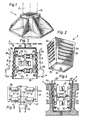
- Figure 1 illustrates a so-called column foundation block 1, i.e. a foundation support for mounting a column 2.
- the block has a central inner, tapering fluted portion 1a.
- the spaces between the ridges of the flutes are called here recesses and are produced by separate, outwardly projecting core parts or sections 3a of a mould core 3 illustrated in Figure 2.
- the core mould is used to form the central opening 1a in the column foundation block 1 when casting said block in a mould 4 shown in chain lines in Figure 3.
- the reference 3c identifies a pin for forming a drainage hole in the cast foundation block (see Figure 4).
- Each of the side surfaces of the mould core 3 has a number of openings or slots 3b in which the recess-forming core parts 3a are arranged for movement between an active, outwardly projecting position shown in Figures 2 and 3, and in inactive position, shown in Figure 4, in which said mould parts are partially withdrawn into the mould core.
- all moveable core parts 3a located adjacent one side surface of the mould core 3 are arranged on a plate 5.
- the plate 5 is acted upon by two pneumatic cylinders 6 having associated piston rods 6a which are pivotally connected to the plate 5 through pivot pins 7.
- the pivot pins are accommodated in holder strips 8 extending at right angles to the surface of the plaffJ.
- the piston rod 6a of the cylinders are connected via pivot pin 7 and holder strip 8 to a plate 5 located on the opposite side surface of the mould core 3, this latter plate 5 also carrying movable core parts 3a.
- the mould core is arranged in a mould 4, shown in chain lines.
- Figure 4 shows the movable core parts 3a withdrawn to their inactive positions, in which stripping from a cast column foundation block 1 can readily be effected, by drawing the mould core 3 upwardly so as to separate it from the foundation block 1.
- Adjustable stop means 10, 10' are arranged to restrict the inward movement of the movable core parts 3 to their inactive positions under the action of respective cylinder 6, 6'.
- Figure 5 is a diagram showing how the cylinders 6, 6' and associated piston rods are controlled.
- T-couplings and cruciform couplings 11 and 12 respectively, all four cylinders and associated piston rods are activated simultaneously, enabling all movable core parts 3a to be moved simultaneously to an active or inactive position by simple manipulation of an operating device 13.
- the mould core 3 When casting a column foundation block, the mould core 3 is placed in a mould 4, it being ensured that the movable core parts 3a take an active position. Concrete is then poured into the mould and allowed to harden while being vibrated. The mould is then stripped, it being assumed here that Figure 4 illustrates that the outer mould walls of the mould 4 have been removed, so that only the column foundation block 1 and the mould core 3 remain.
- the movable core parts 3a are moved to their respective inactive positions by means of the rams 6, 6a, 6', 6'a, whereafter the mould core can be readily separated from the column foundation block.
- the invention thus saves time and expense, since mould setting and stripping can be effected in one working operation, and that all the work can be carried out mechanically. Heavy handling of loose mould sections is completely avoided.
Landscapes
- Engineering & Computer Science (AREA)
- Manufacturing & Machinery (AREA)
- Chemical & Material Sciences (AREA)
- Ceramic Engineering (AREA)
- Mechanical Engineering (AREA)
- Moulds, Cores, Or Mandrels (AREA)
- Casting Devices For Molds (AREA)
Description
- The present invention relates to a method for casting concrete elements, for example column foundation blocks, in a mould while using means advanceable into and retractable from the side-walls of the concrete elements to be cast.
- The invention also refers to a mould core to be received in a mould for casting concrete elements.
- When using mould cores known hitherto, the task of setting and stripping the mould is both complicated and time consuming. The cost of the moulds and associated mould cores is also high. Contributory hereto is, inter alia, the handling difficulties experienced as a result of the completely closed core space.
- In an attempt to avoid these difficulties, one method proposes that the mould core is made of steel and supplemented with loose mould parts. In this way, it is possible to strip the steel core separately towards one free side, and to then loosen the remaining mould parts, which form the recesses in the cast concrete element, by forcing said parts inwardly into the free core space created when removing the steel core.
- Even this method, however, requires doubling of the mould setting operations and time consuming, heavy work in spaces difficult to reach within the mould core. In addition, the loose mould parts must be cleaned and handled, which also means heavy and difficult work.
- In US Patent 2,680,276 (Filangeri) there is described a cesspool mould of large dimensions including inner and outer sectional walls to provide a moulding space. The inner wall sections are provided with tubular guides for core pins constituting advanceable and retractable means which are projectable across the moulding space to form through-going drainage openings in the cesspool wall. When assembling the mould a workman enters through a manhole and engages the core pins mounted by means of bars on a plate with the guides, so that it will be possible to displace the core pins to their projecting position by means of gravity. This method and arrangement are complicated and expensive and possible to use only in very big moulds.
- One object of the present invention is to provide a method of the aforementioned kind by which the disadvantages associated with known methods are avoided and which facilitates the manual work both when setting the mould and when stripping the same.
- Another object of the invention is to provide a novel mould core which facilitates the task of mould setting and mould stripping when casting a concrete element provided with recesses or apertures in its side-walls.
- The method according to the invention is mainly characterized by providing a mould core to be set and stripped as a unit with apertures or slots in which advanceable and retractable core parts for forming recesses can be moved, arranging the recess-forming core parts located on one side surface of the mould core on a plate located within the core and extending substantially parallel to said side surface, moving said plate towards and away from said side surface in a direction substantially at right angles thereto by means of a ram mounted within the core, actuating said ram prior to a casting operation to bring said movable core parts to take an active position projecting outwardly through a corresponding aperture and subsequent to said casting operation actuating said ram to bring said core parts to take an inactive position permitting stripping of the mould.
- The invention affords the important advantage of enabling those mould parts which form flutes or recesses in the cast concrete element to be stripped from the mould together with the actual mould core, the stripping operation being facilitated by the fact that relative displacement of the mould core and the wall of the cast concrete element can be effected parallel with the said wall.
- The invention also relates to a mould core for use when carrying out the aforedescribed method, the main characterizing features of the mould core being set forth in claim 4.
- A mould core of the aforementioned kind is particularly useful with moulds for manufacturing so-called column foundation boxes, i.w. a foundation on which columns or pillars can be mounted. In this respect, the flutes or openings in the cast column foundation block are necessary for transferring horizontal and vertical forces in the column to the foundation. This transfer of forces is effected through a concrete layer cast between the foundation block and the column.
- An embodiment of the invention will now be described in more detail with reference to the accompanying drawing.
-
- Figure 1 is a perspective view of a so-called column foundation block manufactured by means of the method according to the invention, and a column associated with said foundation block.
- Figure 2 is a perspective view of a mould core for use when carrying out the method according to the invention.
- Figure 3 is a sectional view of a mould core according to Figure 2, arranged in a mould, shown in chain lines, with the recess-forming core parts in an active position.
- Figure 4 is a sectional view of a mould core according to Figure 2, and a cast column foundation block during stripping of the mould core, the recess-forming parts of the mould being shown in their inactive position.
- Figure 5 illustrates the operational mode of the pneumatic cylinders and piston rods which act upon the moveable core parts.
- Figure 1 illustrates a so-called column foundation block 1, i.e. a foundation support for mounting a
column 2. In order to ensure that the horizontal and vertical forces acting in the column are reliably transferred to the column foundation block, the block has a central inner, taperingfluted portion 1a. - The spaces between the ridges of the flutes are called here recesses and are produced by separate, outwardly projecting core parts or
sections 3a of amould core 3 illustrated in Figure 2. The core mould is used to form thecentral opening 1a in the column foundation block 1 when casting said block in a mould 4 shown in chain lines in Figure 3. Thereference 3c identifies a pin for forming a drainage hole in the cast foundation block (see Figure 4). - Each of the side surfaces of the
mould core 3 has a number of openings orslots 3b in which the recess-formingcore parts 3a are arranged for movement between an active, outwardly projecting position shown in Figures 2 and 3, and in inactive position, shown in Figure 4, in which said mould parts are partially withdrawn into the mould core. - In the illustrated embodiment, all
moveable core parts 3a located adjacent one side surface of themould core 3 are arranged on aplate 5. Theplate 5 is acted upon by twopneumatic cylinders 6 having associatedpiston rods 6a which are pivotally connected to theplate 5 throughpivot pins 7. The pivot pins are accommodated inholder strips 8 extending at right angles to the surface of the plaffJ. - In a similar manner, the
piston rod 6a of the cylinders are connected viapivot pin 7 andholder strip 8 to aplate 5 located on the opposite side surface of themould core 3, thislatter plate 5 also carryingmovable core parts 3a. - As illustrated in Figure 3, the mould core is arranged in a mould 4, shown in chain lines.
- As illustrated in Figure 4, other
movable core parts 3a located on two mutually opposing sides of the mould core are arranged for movement between an active and an inactive position, by means of plates 5', pivot pins 7', holder strips 8' and pneumatic cylinders 6' with associated piston rods 6'a. In this case, the two cylinders 6' are located on the same level in the interior of themould core 3 and between thecylinders 6 extending at right angles to the axis of the cylinders 6'. - Figure 4 shows the
movable core parts 3a withdrawn to their inactive positions, in which stripping from a cast column foundation block 1 can readily be effected, by drawing themould core 3 upwardly so as to separate it from the foundation block 1. - Adjustable stop means 10, 10' are arranged to restrict the inward movement of the
movable core parts 3 to their inactive positions under the action ofrespective cylinder 6, 6'. - Figure 5 is a diagram showing how the
cylinders 6, 6' and associated piston rods are controlled. By using T-couplings andcruciform couplings movable core parts 3a to be moved simultaneously to an active or inactive position by simple manipulation of anoperating device 13. - When casting a column foundation block, the
mould core 3 is placed in a mould 4, it being ensured that themovable core parts 3a take an active position. Concrete is then poured into the mould and allowed to harden while being vibrated. The mould is then stripped, it being assumed here that Figure 4 illustrates that the outer mould walls of the mould 4 have been removed, so that only the column foundation block 1 and themould core 3 remain. Themovable core parts 3a are moved to their respective inactive positions by means of therams - The invention thus saves time and expense, since mould setting and stripping can be effected in one working operation, and that all the work can be carried out mechanically. Heavy handling of loose mould sections is completely avoided.
- Instead of the illustrated pneumatic operating devices, it is possible to use other types of rams, for example screw jacks or the like.
- The principle of the invention can be applied in many other contexts where the cast concrete element is to be provided with ruffles.
Claims (5)
Priority Applications (1)
| Application Number | Priority Date | Filing Date | Title |
|---|---|---|---|
| AT82850024T ATE20712T1 (en) | 1981-02-17 | 1982-02-12 | PROCESS AND MOLDING CORE FOR CASTING CONCRETE ELEMENTS. |
Applications Claiming Priority (3)
| Application Number | Priority Date | Filing Date | Title |
|---|---|---|---|
| SE8101076 | 1981-02-17 | ||
| SE8101076A SE434479B (en) | 1981-02-17 | 1981-02-17 | SETS AND FORMS FOR CASTING OF CONCRETE ELEMENTS |
| AU10865/83A AU1086583A (en) | 1981-02-17 | 1983-01-27 | Adjustable mould core for casting concrete elements |
Publications (3)
| Publication Number | Publication Date |
|---|---|
| EP0058655A2 EP0058655A2 (en) | 1982-08-25 |
| EP0058655A3 EP0058655A3 (en) | 1983-07-20 |
| EP0058655B1 true EP0058655B1 (en) | 1986-07-16 |
Family
ID=32928266
Family Applications (1)
| Application Number | Title | Priority Date | Filing Date |
|---|---|---|---|
| EP82850024A Expired EP0058655B1 (en) | 1981-02-17 | 1982-02-12 | A method and mould core for casting concrete elements |
Country Status (6)
| Country | Link |
|---|---|
| US (1) | US4471936A (en) |
| EP (1) | EP0058655B1 (en) |
| AU (1) | AU1086583A (en) |
| CA (1) | CA1174437A (en) |
| DE (1) | DE3271969D1 (en) |
| SE (1) | SE434479B (en) |
Cited By (1)
| Publication number | Priority date | Publication date | Assignee | Title |
|---|---|---|---|---|
| WO2004001160A1 (en) * | 2002-06-25 | 2003-12-31 | Rapid Building Systems Pty Ltd | Improved means and method for the manufacture of pre-cast building panels |
Families Citing this family (5)
| Publication number | Priority date | Publication date | Assignee | Title |
|---|---|---|---|---|
| DE3602070A1 (en) * | 1985-02-04 | 1986-08-07 | National Concrete Masonry Association, Herndon, Va. | METHOD AND DEVICE FOR THE BIAXIAL CASTING OF CONCRETE STONE |
| US6740281B2 (en) | 2002-03-04 | 2004-05-25 | The Procter & Gamble Company | Three-dimensional articles of indeterminate axial length |
| US6793192B2 (en) * | 2002-03-04 | 2004-09-21 | The Procter & Gamble Company | Process of making integral three-dimensional articles, and mold for making such articles |
| US8956147B2 (en) | 2011-11-22 | 2015-02-17 | The OHorizons Foundation | Mold for rectangular structure |
| WO2023283679A1 (en) * | 2021-07-14 | 2023-01-19 | Rodney Mackay Sim | Recess former and anchor assembly |
Family Cites Families (8)
| Publication number | Priority date | Publication date | Assignee | Title |
|---|---|---|---|---|
| US929694A (en) * | 1908-10-26 | 1909-08-03 | Henry Noah | Method and apparatus for making culverts of concrete. |
| US2680276A (en) * | 1952-02-07 | 1954-06-08 | Filangeri Dominick | Cesspool mold |
| US3952990A (en) * | 1972-05-18 | 1976-04-27 | Garcia Onofre S | Container type molding device of matched segments |
| US3814374A (en) * | 1972-07-10 | 1974-06-04 | Ameron Inc | Retractable casting core box with elastomeric joint seal |
| FR2239124A5 (en) * | 1973-07-24 | 1975-02-21 | Outinord | Internal shuttering for concrete box sections - has two half shells whose positions are adjusted by rams |
| DE2348655A1 (en) * | 1973-09-27 | 1975-04-17 | Gruenzweig Hartmann Glasfaser | MOLDING DEVICE FOR MANUFACTURING LARGE VOLUME BODIES |
| US4125246A (en) * | 1976-11-05 | 1978-11-14 | Holdt J W Von | Pivot assembly mold apparatus |
| AT359276B (en) * | 1977-11-03 | 1980-10-27 | Metallwarenfabrik Fischamend | Collapsing core for casting molds |
-
1981
- 1981-02-17 SE SE8101076A patent/SE434479B/en not_active IP Right Cessation
-
1982
- 1982-02-10 US US06/347,613 patent/US4471936A/en not_active Expired - Fee Related
- 1982-02-12 DE DE8282850024T patent/DE3271969D1/en not_active Expired
- 1982-02-12 EP EP82850024A patent/EP0058655B1/en not_active Expired
- 1982-02-17 CA CA000396455A patent/CA1174437A/en not_active Expired
-
1983
- 1983-01-27 AU AU10865/83A patent/AU1086583A/en not_active Abandoned
Cited By (1)
| Publication number | Priority date | Publication date | Assignee | Title |
|---|---|---|---|---|
| WO2004001160A1 (en) * | 2002-06-25 | 2003-12-31 | Rapid Building Systems Pty Ltd | Improved means and method for the manufacture of pre-cast building panels |
Also Published As
| Publication number | Publication date |
|---|---|
| SE8101076L (en) | 1982-08-18 |
| EP0058655A2 (en) | 1982-08-25 |
| SE434479B (en) | 1984-07-30 |
| US4471936A (en) | 1984-09-18 |
| DE3271969D1 (en) | 1986-08-21 |
| EP0058655A3 (en) | 1983-07-20 |
| AU1086583A (en) | 1984-08-02 |
| CA1174437A (en) | 1984-09-18 |
Similar Documents
| Publication | Publication Date | Title |
|---|---|---|
| US4218206A (en) | Mold box apparatus | |
| EP1654100B1 (en) | Concrete block mold with moveable liner | |
| US3070867A (en) | Strand holder and dam for prestressed concrete molds | |
| US4471936A (en) | Mould core for casting concrete elements | |
| US4249358A (en) | Process and installation for moulding paving stones or slabs | |
| US4679762A (en) | Form set-up | |
| US6105924A (en) | Wedge apparatus and mold | |
| DE19912829B4 (en) | Plant for the production of cup-shaped concrete bodies | |
| CN212802537U (en) | Bearing column pouring mold for building construction | |
| CN210100272U (en) | Mould and mould set comprising same | |
| KR200278096Y1 (en) | Mold system for manufacturing inner wall of segment in bridge in which ilm pc box girder is applied | |
| CN217840870U (en) | Component is pour fast to frame constructional column | |
| JP3329914B2 (en) | Formwork for culvert block production | |
| CN212123659U (en) | Concrete plate production equipment | |
| CN109822728B (en) | Floating window production device and method | |
| US4289472A (en) | Press for refractory material and having removable core moving apparatus | |
| AU593535B2 (en) | Biaxial concrete masonry casting method and apparatus | |
| CN119145629B (en) | But cyclic utilization's steel form for building | |
| CN214293635U (en) | Precast box girder mould | |
| CN219987953U (en) | Solid recycled concrete precast pile device | |
| JP3087033B2 (en) | Concrete structure automatic molding machine | |
| KR101484757B1 (en) | System formwork the easily of removal of forms | |
| US3083434A (en) | Apparatus for making pre-cast cored building blocks | |
| JPH06170829A (en) | Formwork device | |
| JPH0320082Y2 (en) |
Legal Events
| Date | Code | Title | Description |
|---|---|---|---|
| PUAI | Public reference made under article 153(3) epc to a published international application that has entered the european phase |
Free format text: ORIGINAL CODE: 0009012 |
|
| AK | Designated contracting states |
Designated state(s): AT BE CH DE GB LU NL SE |
|
| PUAL | Search report despatched |
Free format text: ORIGINAL CODE: 0009013 |
|
| AK | Designated contracting states |
Designated state(s): AT BE CH DE GB LI LU NL SE |
|
| 17P | Request for examination filed |
Effective date: 19840107 |
|
| GRAA | (expected) grant |
Free format text: ORIGINAL CODE: 0009210 |
|
| AK | Designated contracting states |
Kind code of ref document: B1 Designated state(s): AT BE CH DE GB LI LU NL SE |
|
| PG25 | Lapsed in a contracting state [announced via postgrant information from national office to epo] |
Ref country code: NL Effective date: 19860716 Ref country code: LI Effective date: 19860716 Ref country code: CH Effective date: 19860716 Ref country code: BE Effective date: 19860716 Ref country code: AT Effective date: 19860716 |
|
| REF | Corresponds to: |
Ref document number: 20712 Country of ref document: AT Date of ref document: 19860815 Kind code of ref document: T |
|
| PG25 | Lapsed in a contracting state [announced via postgrant information from national office to epo] |
Ref country code: SE Effective date: 19860731 |
|
| REF | Corresponds to: |
Ref document number: 3271969 Country of ref document: DE Date of ref document: 19860821 |
|
| REG | Reference to a national code |
Ref country code: CH Ref legal event code: PL |
|
| NLV1 | Nl: lapsed or annulled due to failure to fulfill the requirements of art. 29p and 29m of the patents act | ||
| PG25 | Lapsed in a contracting state [announced via postgrant information from national office to epo] |
Ref country code: LU Free format text: LAPSE BECAUSE OF NON-PAYMENT OF DUE FEES Effective date: 19870228 |
|
| PLBE | No opposition filed within time limit |
Free format text: ORIGINAL CODE: 0009261 |
|
| STAA | Information on the status of an ep patent application or granted ep patent |
Free format text: STATUS: NO OPPOSITION FILED WITHIN TIME LIMIT |
|
| 26N | No opposition filed | ||
| PGFP | Annual fee paid to national office [announced via postgrant information from national office to epo] |
Ref country code: GB Payment date: 19900228 Year of fee payment: 9 |
|
| PG25 | Lapsed in a contracting state [announced via postgrant information from national office to epo] |
Ref country code: GB Effective date: 19910212 |
|
| GBPC | Gb: european patent ceased through non-payment of renewal fee | ||
| PGFP | Annual fee paid to national office [announced via postgrant information from national office to epo] |
Ref country code: DE Payment date: 19980224 Year of fee payment: 17 |
|
| PG25 | Lapsed in a contracting state [announced via postgrant information from national office to epo] |
Ref country code: DE Free format text: LAPSE BECAUSE OF NON-PAYMENT OF DUE FEES Effective date: 19991201 |