EP0058521B1 - Tape guide device - Google Patents
Tape guide device Download PDFInfo
- Publication number
- EP0058521B1 EP0058521B1 EP82300681A EP82300681A EP0058521B1 EP 0058521 B1 EP0058521 B1 EP 0058521B1 EP 82300681 A EP82300681 A EP 82300681A EP 82300681 A EP82300681 A EP 82300681A EP 0058521 B1 EP0058521 B1 EP 0058521B1
- Authority
- EP
- European Patent Office
- Prior art keywords
- tape
- drum
- guide
- fixed base
- attaching members
- Prior art date
- Legal status (The legal status is an assumption and is not a legal conclusion. Google has not performed a legal analysis and makes no representation as to the accuracy of the status listed.)
- Expired
Links
Images


Classifications
-
- G—PHYSICS
- G11—INFORMATION STORAGE
- G11B—INFORMATION STORAGE BASED ON RELATIVE MOVEMENT BETWEEN RECORD CARRIER AND TRANSDUCER
- G11B15/00—Driving, starting or stopping record carriers of filamentary or web form; Driving both such record carriers and heads; Guiding such record carriers or containers therefor; Control thereof; Control of operating function
- G11B15/60—Guiding record carrier
- G11B15/61—Guiding record carrier on drum, e.g. drum containing rotating heads
Definitions
- the present invention relates to a tape guide device for guiding a tape around the periphery of a drum.
- the tape transport system of a broadcasting helical VTR Video Tape Recorder
- SMPTE Society of Motion Picture and Television Engineers
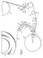
- Fig. 1 of the accompanying drawings The tape transport system of a broadcasting helical VTR (Video Tape Recorder), having an SMPTE (Society of Motion Picture and Television Engineers) type-C format is generally constructed as shown in Fig. 1 of the accompanying drawings.
- reference numeral 1 denotes a tape supply side reel base
- 2 a tape take-up side reel base
- numerals 3 to 5 denote guide rollers, respectively.
- Numeral 6 designates a tape tension adjusting device placed in the tape supply side which includes a tension arm 7 and a fixed post 8 attached, in this example, at the top thereof.
- the tension arm 7 is adjusted to stay at a position designated by numeral 7b (slightly to one side of the line tangential to the guide rollers 3 and 4) for minimum tension (0g) and is adjusted to stay at a position designated by numeral 7a (slightly to the other side of the line tangential to the guide rollers 3 and 4) for maximum tension (about 400g).
- Numeral 10 represents a rotary drum which is provided with a rotary magnetic head assembly and around which a magnetic tape 11 is wound to form an omega-shape by a guide post 12 having a taper and located at the tape entry side and a pair of tape guides 13 and 14 for restricting the winding angle of the tape.
- Numeral 15 represents an impedance roller, 16 a head for erasing the full width of the tape, 17 an erasing head for erasing an audio signal in an audio signal track, 18 a recording/reproducing head for recording/reproducing the audio signal and 19 represents a head for monitoring the audio signal.
- numeral 20 designates a guide post
- 21 a capstan, 22 a pinch roller, 23 a time roller and 25 represents an adjusting device for adjusting the tape tension of the take-up side in which numeral 26 represents a tension arm and 27 denotes a fixed post, which is adjusted to a position denoted by numeral 26a for maximum tension or to a position denoted by numeral 26b for minimum tension.
- the magnetic tape 11 is wound around the rotary drum 10 in an omega-shaped path, so that the space or distance between the pair of the tape guides 13 and 14 and the space or distance between these tape guides 13,14 and the peripheral surface of the rotary drum 10 are extremely narrow. Hence, it is quite difficult to put the tape 11 around the rotary drum 10 and in addition, there is the risk that the tape 11 may be damaged during wrapping of the tape around the drum 10.
- a tape guide device in which a tape is omega-wrapped around the periphery of a drum by a pair of tape guides spaced a short distance from the periphery of the drum, the device comprising a fixed base located in a predetermined position relative to the external periphery of the drum and a pair of guide attaching members provided on an upper plane thereof to attach said tape guides, characterised in that the guide attaching members are freely movable relative to said fixed base, and-th p arrangement is such that while the tape is being wrapped around on said drum, said guide attaching members are moved to be spaced by a predetermined larger distance from said periphery of the drum.
- the chain line in Figure 1 shows how the tape guides 13 and 14, the guide post 12, the guide roller 5 and the erasing head 16 can be moved together.
- a fixed base or base plate 30 at a predetermined position on the external periphery of the drum 10.
- the fixed base 30 has a predetermined step and its cross-section is formed to be substantially crank- shape, so that its plane on the tape feed side is higher by a predetermined amount than its plane on its tape entry side as illustrated in Figure 3. This is because the tape 11 is wound around the drum 10 in order that the plane on the entry side of the tape 11 and the plane on the feed side of the tape 11 may have the predetermined steps, respectively.
- the end surface of the fixed base 30 opposing the drum 10 is formed nearly the same as the peripheral surface of the drum 10 and, as shown in Figure 4, fixed shafts 32A and 32B of column shape (as to the fixed shaft 32A, refer to Figure 2) are provided at predetermined positions of the end surfaces 31A and 31 B which form the planes of the tape entry and feed sides so as to abut the external surface of a lower drum 10A.
- these shafts 32A and '32B are the locating members of the fixed base 30 for the drum 10 which are used to position the pair of tape guides 13 and 14 provided on the fixed base 30 relative to the drum 10 whereby the fixed base 30, in the condition that the fixed shafts 32A and 32B are abutted to the lower drum 10A, is slightly displaced right and left so that the locations of the tape guides 13 and 14 relative to the drum 10 can be correctly adjusted.
- the fixed base 30 is secured to a chassis 35 by screws 34a to 34d.
- guide attaching members or bodies 40 and 50 are provided so as to be freely movable which install the tape guides 13 and 14 thereon. Since these guide attaching members 40 and 50 are constructed the same as one other, a description will be given by one of these guide attaching members 40 and 50, for example, the guide attaching member 40 located on the tape entry side for installing the tape guide 13 and description of the guide attaching member 50 will be omitted for simplicity.
- the guide attaching member 40 mounted on the tape entry side includes a slide plate 41 which can move in a direction (shown by an arrow a in Figure 2) parallel to a cutting-plane line I-I in Figure 2 and an adjusting mechanism 42 of the tape guide 13 provided proximate the drum 10 on the upper plane of the slide plate 41.
- the adjusting mechanism 42 is so formed that its height and inclination can be adjusted independently and the tape guide 13 is attached to the corner of the adjusting mechanism 42 as seen in Figure 2 and 4.
- the slide plate 41 is constructed in such a manner that it can be slid by a predetermined distance in the direction shown by the arrow a in Figure 2 using a sliding mechanism 44 as illustrated in Figure 5.
- a sliding plate 41 having a reversed U-shape cross-section is used.
- the sliding mechanism 44 is disposed within the U-shape surrounded by both end portions 41 a and 41 b.
- the sliding mechanism 44 is comprised of an inside race 45 attached to the fixed base 30 in which V-shape grooves are formed on both side surfaces and outside races 46 and 47 attached to the inner surfaces of the end portions 41a a and 41b which include V-shape grooves likewise. Between the spaces defined by the inside and outside races 45 to 47 are inserted balls 48 as illustrated in Figure 5 thereby enabling the slide plate 41 to be slid in the direction shown by the arrow a by a predetermined distance without shaking the slide plate 41.
- a column-shaped stop 49 having a predetermined diameter so as to oppose the inside race 45.
- the projected length of the stop 49 is so selected that the inside race 45 may closely contact the stop 49 at the extreme sliding position where the slide plate 41 is as seen in Figure 2.
- Numeral 60 generally denotes a transmitting force from the motor M to the slide plate 41 in which one end of a lever 62 is attached to a fulcrum 61 located in a predetermined position on the slide plate 41 and between the other end thereof and a fixed plate 63 attached to the slide plate 41 is located a pressure setting mechanism 65 for setting the force to be applied to the movable lever 62 as constant, which mechanism includes a stepped bar 66 and a pressure spring 67.
- a fulcrum 68 located in the center of the movable lever 62 is attached a first link 69 and the other end of the first link 69 is attached to a fulcrum 71 on one flange of a central shaft 70 which is pivotally fixed to the fixed base 30.
- a fulcrum 72 on another flange is attached a second link 73 and the other end of this second link 73 is attached to a rotary shaft 74 of the motor M.
- Numeral 75 designates an attaching arm thereof and 76 designates a fulcrum thereof.
- the guide post 12 is attached to this slide plate 41.
- the guide attaching member 50 for the other tape guide 14 is also constructed as described above, and is slidably moved in a direction shown by an arrow b in Figure 2.
- Numeral 51 represents a slide plate and 52 represents a guide adjusting mechanism thereof.
- numeral 59 represents a stop.
- a second transmitting mechanism 80 for transmitting the rotational force of the motor M to the slide plate 51 in which numeral 82 denotes a movable lever, 89 a third link and numeral 90 denotes a central shaft located on the fixed base 30.
- numerals 81, 88 and 91 each denote fulcrums.
- the guide roller 5 is provided on the slide plate 51.
- the motor M is just driven so that the tape guides 13 and 14, the guide post 12 and the guide roller 5 are respectively spaced apart in the respective directions shown by the arrows a and b in Figure 2 thereby to permit the width between tape guides 13 and 14, the width between the guide post 12 and the guide roller 5 and the width between the drum 10 and the tape guides 13, 14 to be widened or enlarged respectively and then the loading of the tape 11 can be performed quite easily.
- the tape guides 13 and 14 are adapted to depart from the drum 10 during the loading of the tape, it is quite easy to put the tape 11 on the drum 10. In addition, damage to the tape 11 can be prevented.
- the loading of the tape becomes easier than ever. Then, if the full track erasing head 16 is moved to the position as shown by the chained line in Figure 1 in addition to the provision of the sliding mechanism according to the present invention, needless to say that the loading of the tape can be carried our more easily.
- the guide attaching members 40 and 50 are mounted on the fixed base 30, even when the fixed base 30 is moved, the position of the dropout in the video signal can be finely adjusted with accuracy while the dropout amount of the video signal is not changed.
- the motor M is mounted on the chassis 35, it is required to adjust the relation between the motor M and the transmitting mechanism 60 each time the fixed base 30 is adjusted. But there is no such necessity with the illustrated tape guide device.
- the present invention has been described as applied to the tape guide device of a VTR having the SMPTE type-C format, the present invention is also applicable to the tape guide device of other VTRs with the same effect.
Abstract
Description
- The present invention relates to a tape guide device for guiding a tape around the periphery of a drum.
- The tape transport system of a broadcasting helical VTR (Video Tape Recorder), having an SMPTE (Society of Motion Picture and Television Engineers) type-C format is generally constructed as shown in Fig. 1 of the accompanying drawings.
- In the figure,
reference numeral 1 denotes a tape supply side reel base, 2 a tape take-up side reel base and numerals 3 to 5 denote guide rollers, respectively. Numeral 6 designates a tape tension adjusting device placed in the tape supply side which includes a tension arm 7 and afixed post 8 attached, in this example, at the top thereof. The tension arm 7 is adjusted to stay at a position designated bynumeral 7b (slightly to one side of the line tangential to the guide rollers 3 and 4) for minimum tension (0g) and is adjusted to stay at a position designated bynumeral 7a (slightly to the other side of the line tangential to the guide rollers 3 and 4) for maximum tension (about 400g). -
Numeral 10 represents a rotary drum which is provided with a rotary magnetic head assembly and around which amagnetic tape 11 is wound to form an omega-shape by aguide post 12 having a taper and located at the tape entry side and a pair oftape guides Numeral 15 represents an impedance roller, 16 a head for erasing the full width of the tape, 17 an erasing head for erasing an audio signal in an audio signal track, 18 a recording/reproducing head for recording/reproducing the audio signal and 19 represents a head for monitoring the audio signal. - Also,
numeral 20 designates a guide post, 21 a capstan, 22 a pinch roller, 23 a time roller and 25 represents an adjusting device for adjusting the tape tension of the take-up side in whichnumeral 26 represents a tension arm and 27 denotes a fixed post, which is adjusted to a position denoted bynumeral 26a for maximum tension or to a position denoted bynumeral 26b for minimum tension. - By the way, in the VTR with the type C format just described, the
magnetic tape 11 is wound around therotary drum 10 in an omega-shaped path, so that the space or distance between the pair of thetape guides tape guides rotary drum 10 are extremely narrow. Hence, it is quite difficult to put thetape 11 around therotary drum 10 and in addition, there is the risk that thetape 11 may be damaged during wrapping of the tape around thedrum 10. - According to the present invention there is provided a tape guide device in which a tape is omega-wrapped around the periphery of a drum by a pair of tape guides spaced a short distance from the periphery of the drum, the device comprising a fixed base located in a predetermined position relative to the external periphery of the drum and a pair of guide attaching members provided on an upper plane thereof to attach said tape guides, characterised in that the guide attaching members are freely movable relative to said fixed base, and-thp arrangement is such that while the tape is being wrapped around on said drum, said guide attaching members are moved to be spaced by a predetermined larger distance from said periphery of the drum.
- The invention will be further described by way of example with reference to the accompanying drawings in which:-
- Figure 1 is a diagram showing one example 'of a tape transporting system of a VTR used to explain the present invention;
- Figure 2 is a plan diagram showing one example of the tape guide device according to the present invention;
- Figure 3 is a cross-sectional diagram taken along a line I-I in Figure 2;
- Figure 4 is a left side diagram of Figure 2;
- Figure 5 is an enlarged longitudinal cross-sectional diagram of a slide plate;
- Figure 6 is a diagram of a back side of a fixed base plate;
- Figure 7 is a plan diagram showing a state after the slide plates are slid; and
- Figure 8 is a longitudinal sectional diagram thereof.
- The chain line in Figure 1 shows how the tape guides 13 and 14, the
guide post 12, theguide roller 5 and the erasinghead 16 can be moved together. - An example of a tape guide device according to the present invention will hereinafter be described with reference to Figure 2 and the following figures. The following description relates to the case where the pair of the
tape guides guide post 12 and theguide roller 5 are constructed as movable. - As shown in Figure 2, there is provided a fixed base or
base plate 30 at a predetermined position on the external periphery of thedrum 10. Thefixed base 30 has a predetermined step and its cross-section is formed to be substantially crank- shape, so that its plane on the tape feed side is higher by a predetermined amount than its plane on its tape entry side as illustrated in Figure 3. This is because thetape 11 is wound around thedrum 10 in order that the plane on the entry side of thetape 11 and the plane on the feed side of thetape 11 may have the predetermined steps, respectively. - The end surface of the
fixed base 30 opposing thedrum 10 is formed nearly the same as the peripheral surface of thedrum 10 and, as shown in Figure 4, fixedshafts fixed shaft 32A, refer to Figure 2) are provided at predetermined positions of theend surfaces lower drum 10A. - As will be described later, these
shafts 32A and '32B are the locating members of thefixed base 30 for thedrum 10 which are used to position the pair oftape guides fixed base 30 relative to thedrum 10 whereby thefixed base 30, in the condition that thefixed shafts lower drum 10A, is slightly displaced right and left so that the locations of thetape guides drum 10 can be correctly adjusted. - The reason why such adjusting method is adopted is as follows. In a VTR with the type C format, since a video record vertical-interval dropout location, or position and dropout amount (10 + 0.25 horizontal lines) are standardized by the SMPTE it is desirable to adjust only the dropout position correctly without changing the dropout amount.
- After the attached position being adjusted, the
fixed base 30 is secured to achassis 35 byscrews 34a to 34d. - On the upper plane of the
fixed base 30 guide attaching members orbodies tape guides guide attaching members guide attaching members guide attaching member 40 located on the tape entry side for installing thetape guide 13 and description of theguide attaching member 50 will be omitted for simplicity. Theguide attaching member 40 mounted on the tape entry side includes aslide plate 41 which can move in a direction (shown by an arrow a in Figure 2) parallel to a cutting-plane line I-I in Figure 2 and anadjusting mechanism 42 of thetape guide 13 provided proximate thedrum 10 on the upper plane of theslide plate 41. - As is well-known in the prior art, the
adjusting mechanism 42 is so formed that its height and inclination can be adjusted independently and thetape guide 13 is attached to the corner of theadjusting mechanism 42 as seen in Figure 2 and 4. - The
slide plate 41 is constructed in such a manner that it can be slid by a predetermined distance in the direction shown by the arrow a in Figure 2 using asliding mechanism 44 as illustrated in Figure 5. In this example, is asliding plate 41, having a reversed U-shape cross-section is used. Thesliding mechanism 44 is disposed within the U-shape surrounded by bothend portions 41 a and 41 b. As shown in the figure, thesliding mechanism 44 is comprised of aninside race 45 attached to thefixed base 30 in which V-shape grooves are formed on both side surfaces andoutside races end portions 41a a and 41b which include V-shape grooves likewise. Between the spaces defined by the inside andoutside races 45 to 47 are insertedballs 48 as illustrated in Figure 5 thereby enabling theslide plate 41 to be slid in the direction shown by the arrow a by a predetermined distance without shaking theslide plate 41. - In this case, as shown in Figure 3, at another end portion 41 C of the
slide plate 41 is attached a column-shaped stop 49 having a predetermined diameter so as to oppose theinside race 45. The projected length of thestop 49 is so selected that theinside race 45 may closely contact thestop 49 at the extreme sliding position where theslide plate 41 is as seen in Figure 2. - By these arrangements, even if the
tape guide 13 is constructed to be freely movable, when thetape guide 13 is slid to the position as shown in Figure 2, the position, the height and the inclination of thetape guide 13 always meet the position, the height and the inclination specified beforehand. Accordingly, it is not necessary to adjust the height and so on of the tape guide each time the tape is put on the drum. - Since the
inside race 45 and thestop 49 are enclosed within theslide plate 41, dust does not affect the slide's operation and the stop positions of theslide plate 41. - As shown in Figure 2, the
aforesaid slide plate 41 driven by amotor M. Numeral 60 generally denotes a transmitting force from the motor M to theslide plate 41 in which one end of alever 62 is attached to afulcrum 61 located in a predetermined position on theslide plate 41 and between the other end thereof and afixed plate 63 attached to theslide plate 41 is located apressure setting mechanism 65 for setting the force to be applied to themovable lever 62 as constant, which mechanism includes astepped bar 66 and apressure spring 67. - At a
fulcrum 68 located in the center of themovable lever 62 is attached afirst link 69 and the other end of thefirst link 69 is attached to afulcrum 71 on one flange of acentral shaft 70 which is pivotally fixed to thefixed base 30. At afulcrum 72 on another flange is attached asecond link 73 and the other end of thissecond link 73 is attached to arotary shaft 74 of the motor M. Numeral 75 designates an attaching arm thereof and 76 designates a fulcrum thereof. - In this case, the
guide post 12 is attached to thisslide plate 41. - The
guide attaching member 50 for theother tape guide 14 is also constructed as described above, and is slidably moved in a direction shown by an arrow b in Figure 2.Numeral 51 represents a slide plate and 52 represents a guide adjusting mechanism thereof. Also, as shown in Figure 3, numeral 59 represents a stop. On theguide attaching member 50 is located asecond transmitting mechanism 80 for transmitting the rotational force of the motor M to theslide plate 51 in whichnumeral 82 denotes a movable lever, 89 a third link andnumeral 90 denotes a central shaft located on thefixed base 30.Numerals guide roller 5 is provided on theslide plate 51. - These
guide attaching members drum 10 when the rotation force of the motor M is transmitted thereto. To this end, at the respective lower ends of thecentral shafts arms fulcrums fourth link 94. In that case, thisfourth link 94 extends under the fixed base 30 (refer to Figure 3). - Accordingly, if the motor M makes a half turn from the state shown in Figure 2 in the anti-clockwise direction whereby the
central shaft 70 is urged to rotate in the anti-clockwise direction by a predetermined angle, so that this rotation force is transmitted to theslide plate 41 by way of thefirst link 69 thereby allowing theslide plate 41 to be slid to the right side by a predetermined distance. Figure 7 shows theslide plate 41 slid to the state as described above. - When the
central shaft 70 is turned in the anti-clockwise direction, anothercentral shaft 90 is likewise forced to rotate in the anti-clockwise direction through thefourth link 94, by which thethird link 89 draws theslide plate 51 near thecentral shaft 90 side, thus causing the tape guide 14to depart from thedrum 10 by a predetermined distance (refer to Figs. 7 and 8). - As depicted above, to load the
tape 11 on thedrum 10, the motor M is just driven so that thetape guides guide post 12 and theguide roller 5 are respectively spaced apart in the respective directions shown by the arrows a and b in Figure 2 thereby to permit the width betweentape guides guide post 12 and theguide roller 5 and the width between thedrum 10 and thetape guides tape 11 can be performed quite easily. - After the
tape 11 is put on thedrum 10, if the motor M makes a further half turn, theslide plates respective slide plates stop 49 and 59 as shown in Figure 3. Therefore, since theseslide plates stop 49 and 59 thereof closely contact theinside races mechanisms - It does not matter if the motor M attempts to exert too much force on the
slide plates pressure setting mechanisms - As described above, in accordance with the embodiment of the present invention, since the tape guides 13 and 14 are adapted to depart from the
drum 10 during the loading of the tape, it is quite easy to put thetape 11 on thedrum 10. In addition, damage to thetape 11 can be prevented. - Further, if, in the illustrated embodiment of the present invention, the
guide post 12 and theguide roller 5 adjacent to the tape guides 13 and 14 and the tape guides 13 and 14 themselves are all detached from thedrum 10, the loading of the tape becomes easier than ever. Then, if the fulltrack erasing head 16 is moved to the position as shown by the chained line in Figure 1 in addition to the provision of the sliding mechanism according to the present invention, needless to say that the loading of the tape can be carried our more easily. - Also, since the
guide attaching members base 30, even when the fixedbase 30 is moved, the position of the dropout in the video signal can be finely adjusted with accuracy while the dropout amount of the video signal is not changed. In this case, when the motor M is mounted on thechassis 35, it is required to adjust the relation between the motor M and thetransmitting mechanism 60 each time the fixedbase 30 is adjusted. But there is no such necessity with the illustrated tape guide device. - Further, while in the above described embodiment the present invention has been described as applied to the tape guide device of a VTR having the SMPTE type-C format, the present invention is also applicable to the tape guide device of other VTRs with the same effect.
Claims (5)
Priority Applications (1)
| Application Number | Priority Date | Filing Date | Title |
|---|---|---|---|
| AT82300681T ATE13234T1 (en) | 1981-02-12 | 1982-02-11 | TAPE GUIDE DEVICE. |
Applications Claiming Priority (2)
| Application Number | Priority Date | Filing Date | Title |
|---|---|---|---|
| JP19257/81 | 1981-02-12 | ||
| JP56019257A JPS57133551A (en) | 1981-02-12 | 1981-02-12 | Tape guide device |
Publications (2)
| Publication Number | Publication Date |
|---|---|
| EP0058521A1 EP0058521A1 (en) | 1982-08-25 |
| EP0058521B1 true EP0058521B1 (en) | 1985-05-08 |
Family
ID=11994371
Family Applications (1)
| Application Number | Title | Priority Date | Filing Date |
|---|---|---|---|
| EP82300681A Expired EP0058521B1 (en) | 1981-02-12 | 1982-02-11 | Tape guide device |
Country Status (5)
| Country | Link |
|---|---|
| EP (1) | EP0058521B1 (en) |
| JP (1) | JPS57133551A (en) |
| AT (1) | ATE13234T1 (en) |
| CA (1) | CA1188413A (en) |
| DE (1) | DE3263623D1 (en) |
Family Cites Families (10)
| Publication number | Priority date | Publication date | Assignee | Title |
|---|---|---|---|---|
| JPS418936Y1 (en) * | 1964-02-25 | 1966-04-28 | ||
| US3636275A (en) * | 1968-07-03 | 1972-01-18 | Akai Electric | Headblock assembly of a magnetic video tape recorder |
| JPS5154314Y2 (en) * | 1972-05-29 | 1976-12-25 | ||
| JPS5022644U (en) * | 1973-06-20 | 1975-03-13 | ||
| JPS5031007A (en) * | 1973-07-25 | 1975-03-27 | ||
| US3943566A (en) * | 1974-07-17 | 1976-03-09 | International Business Machines Corporation | Dynamic skew correction for rotating head magnetic recorder |
| JPS5247698A (en) * | 1975-10-15 | 1977-04-15 | Hochiki Corp | Alarm device |
| JPS5549359U (en) * | 1978-09-25 | 1980-03-31 | ||
| JPS5552552A (en) * | 1978-10-09 | 1980-04-17 | Shiro Okamura | Reproducing device |
| JPS6058538B2 (en) * | 1979-04-02 | 1985-12-20 | ソニー株式会社 | Tape loading device |
-
1981
- 1981-02-12 JP JP56019257A patent/JPS57133551A/en active Granted
-
1982
- 1982-02-10 CA CA000395992A patent/CA1188413A/en not_active Expired
- 1982-02-11 AT AT82300681T patent/ATE13234T1/en not_active IP Right Cessation
- 1982-02-11 EP EP82300681A patent/EP0058521B1/en not_active Expired
- 1982-02-11 DE DE8282300681T patent/DE3263623D1/en not_active Expired
Also Published As
| Publication number | Publication date |
|---|---|
| EP0058521A1 (en) | 1982-08-25 |
| JPS57133551A (en) | 1982-08-18 |
| CA1188413A (en) | 1985-06-04 |
| ATE13234T1 (en) | 1985-05-15 |
| DE3263623D1 (en) | 1985-06-13 |
| JPS6348091B2 (en) | 1988-09-27 |
Similar Documents
| Publication | Publication Date | Title |
|---|---|---|
| US3758048A (en) | Tape cassette | |
| EP0187024B1 (en) | Tape-draw out mechanism | |
| US4761697A (en) | Cassette loading mechanism of magnetic recording and reproducing apparatus | |
| JP2993522B2 (en) | Tape tension adjusting device and recording / reproducing device | |
| US4991039A (en) | Apparatus for detecting tape-end | |
| EP0058521B1 (en) | Tape guide device | |
| US5093752A (en) | Device for moving capstan into position after tape is loaded | |
| US4740850A (en) | Magnetic tape loading apparatus for tape recorder | |
| JPS6356618B2 (en) | ||
| US5036411A (en) | Magnetic tape transport mechanism which absorbs magnetic tape oscillations and vibrations in the vicinity of a rotational drum | |
| US4152735A (en) | Tape transport arrangement for tensioning and transporting a magnetic tape | |
| US4486799A (en) | Tape guide device for video tape recorder | |
| US3693908A (en) | Anti-vibration device for tape transports | |
| JP2709161B2 (en) | Tape position adjustment device | |
| KR0113203Y1 (en) | Equipment for high speed tape running of magnetic recording/reproducing apparatus | |
| JPS5935886Y2 (en) | magnetic recording and reproducing device | |
| KR100422013B1 (en) | Supporting apparatus of Tape-end detecting sensor for magnetic recording/reading apparatus | |
| JPH0313894Y2 (en) | ||
| JPH0313661B2 (en) | ||
| JPH0337148Y2 (en) | ||
| KR0136470Y1 (en) | Tension pole driving system | |
| JPS59186162A (en) | Magnetic recording and reproducing device | |
| JP3613844B2 (en) | Magnetic recording / reproducing device | |
| JP2580578B2 (en) | Magnetic recording / reproducing device | |
| GB2049258A (en) | A video tape recorder |
Legal Events
| Date | Code | Title | Description |
|---|---|---|---|
| PUAI | Public reference made under article 153(3) epc to a published international application that has entered the european phase |
Free format text: ORIGINAL CODE: 0009012 |
|
| AK | Designated contracting states |
Designated state(s): AT DE FR GB NL |
|
| 17P | Request for examination filed |
Effective date: 19830204 |
|
| GRAA | (expected) grant |
Free format text: ORIGINAL CODE: 0009210 |
|
| AK | Designated contracting states |
Designated state(s): AT DE FR GB NL |
|
| REF | Corresponds to: |
Ref document number: 13234 Country of ref document: AT Date of ref document: 19850515 Kind code of ref document: T |
|
| REF | Corresponds to: |
Ref document number: 3263623 Country of ref document: DE Date of ref document: 19850613 |
|
| ET | Fr: translation filed | ||
| PLBE | No opposition filed within time limit |
Free format text: ORIGINAL CODE: 0009261 |
|
| STAA | Information on the status of an ep patent application or granted ep patent |
Free format text: STATUS: NO OPPOSITION FILED WITHIN TIME LIMIT |
|
| 26N | No opposition filed | ||
| PGFP | Annual fee paid to national office [announced via postgrant information from national office to epo] |
Ref country code: DE Payment date: 20010205 Year of fee payment: 20 |
|
| PGFP | Annual fee paid to national office [announced via postgrant information from national office to epo] |
Ref country code: GB Payment date: 20010207 Year of fee payment: 20 |
|
| PGFP | Annual fee paid to national office [announced via postgrant information from national office to epo] |
Ref country code: AT Payment date: 20010213 Year of fee payment: 20 Ref country code: FR Payment date: 20010213 Year of fee payment: 20 |
|
| PGFP | Annual fee paid to national office [announced via postgrant information from national office to epo] |
Ref country code: NL Payment date: 20010228 Year of fee payment: 20 |
|
| REG | Reference to a national code |
Ref country code: GB Ref legal event code: IF02 |
|
| PG25 | Lapsed in a contracting state [announced via postgrant information from national office to epo] |
Ref country code: GB Free format text: LAPSE BECAUSE OF EXPIRATION OF PROTECTION Effective date: 20020210 |
|
| PG25 | Lapsed in a contracting state [announced via postgrant information from national office to epo] |
Ref country code: NL Free format text: LAPSE BECAUSE OF EXPIRATION OF PROTECTION Effective date: 20020211 Ref country code: AT Free format text: LAPSE BECAUSE OF EXPIRATION OF PROTECTION Effective date: 20020211 |
|
| REG | Reference to a national code |
Ref country code: GB Ref legal event code: PE20 Effective date: 20020210 |
|
| NLV7 | Nl: ceased due to reaching the maximum lifetime of a patent |