EP0057580B1 - Gestellanordnung für elektronische Anlagen - Google Patents
Gestellanordnung für elektronische Anlagen Download PDFInfo
- Publication number
- EP0057580B1 EP0057580B1 EP82300455A EP82300455A EP0057580B1 EP 0057580 B1 EP0057580 B1 EP 0057580B1 EP 82300455 A EP82300455 A EP 82300455A EP 82300455 A EP82300455 A EP 82300455A EP 0057580 B1 EP0057580 B1 EP 0057580B1
- Authority
- EP
- European Patent Office
- Prior art keywords
- casing
- panel
- mounting
- shelf
- shelves
- Prior art date
- Legal status (The legal status is an assumption and is not a legal conclusion. Google has not performed a legal analysis and makes no representation as to the accuracy of the status listed.)
- Expired
Links
Images


Classifications
-
- H—ELECTRICITY
- H05—ELECTRIC TECHNIQUES NOT OTHERWISE PROVIDED FOR
- H05K—PRINTED CIRCUITS; CASINGS OR CONSTRUCTIONAL DETAILS OF ELECTRIC APPARATUS; MANUFACTURE OF ASSEMBLAGES OF ELECTRICAL COMPONENTS
- H05K7/00—Constructional details common to different types of electric apparatus
- H05K7/18—Construction of rack or frame
-
- H—ELECTRICITY
- H05—ELECTRIC TECHNIQUES NOT OTHERWISE PROVIDED FOR
- H05K—PRINTED CIRCUITS; CASINGS OR CONSTRUCTIONAL DETAILS OF ELECTRIC APPARATUS; MANUFACTURE OF ASSEMBLAGES OF ELECTRICAL COMPONENTS
- H05K7/00—Constructional details common to different types of electric apparatus
- H05K7/14—Mounting supporting structure in casing or on frame or rack
- H05K7/1422—Printed circuit boards receptacles, e.g. stacked structures, electronic circuit modules or box like frames
- H05K7/1424—Card cages
- H05K7/1425—Card cages of standardised dimensions, e.g. 19"-subrack
-
- H—ELECTRICITY
- H05—ELECTRIC TECHNIQUES NOT OTHERWISE PROVIDED FOR
- H05K—PRINTED CIRCUITS; CASINGS OR CONSTRUCTIONAL DETAILS OF ELECTRIC APPARATUS; MANUFACTURE OF ASSEMBLAGES OF ELECTRICAL COMPONENTS
- H05K7/00—Constructional details common to different types of electric apparatus
- H05K7/14—Mounting supporting structure in casing or on frame or rack
- H05K7/1438—Back panels or connecting means therefor; Terminals; Coding means to avoid wrong insertion
- H05K7/1447—External wirings; Wiring ducts; Laying cables
- H05K7/1449—External wirings; Wiring ducts; Laying cables with connections to the back board
Definitions
- Fig. 1 is a perspective view of a skeleton structure of a unitary casing
- Fig. 2 is a perspective view of a skeleton structure in which a plurality of casings are formed as a unitary structure in accordance with the scale of the electronic equipment.
- Shelves each comprising a plurality of electronic circuit packages are mounted between the two shelf mounting posts 4.
- the two posts 1 located in the front of the structure have interfered with the operation and the mounting efficiency has hitherto been low with respect to the shelves.
- attachments such as side boards, a front door, a front cover, etc.
- attachments should be provided with specific metal fixtures for fixing them in place. This increases the number of parts and the operation steps involved in building a casing.
- FR-A-211034 International Standard Electric Corporation
- US-A-2959715 Leonchich
- Electrical Communication volume 47, No. 3, 1972, pages 140-150 (Evans et al).
- FR-A--211034 and US-A-2859715 show instrument racks with left and right posts each formed by a single member and provided with mounting portions for shelves, a floorboard and a ceiling board.
- US-A-2959715 upon which the prior art portion of claim 1 is based, additionally has a reinforcing bent portion extending longitudinally of the post and provided with louvers (70) so that a ventilation channel is provided for heat dissipation.
- the object of the present invention is to provide a casing for electronic equipment small in the number of component parts and requiring a reduced number of installation steps that can be built with a high degree of efficiency and in which there is built in a protected channel for receiving the cables and the number of cable drawing steps is reduced.
- convection inducing plates are mounted for promoting convection of the air heated by the electronic circuits.
- the invention is characterized as set out in the characterizing portion of claim 1.
- the side panels comprising the posts as well as providing for the mounting a plurality of . shelves, the attaching of a back board, the mounting of a ceiling board, and the mounting of a floor board, provide a protected recess for receipt of the cables in a readily accessible manner.
- the most important constructional features of the invention comprise a pair of side posts or a left post and a right post arranged on opposite sides of the casing.
- the left post and the right post are large in width and each perform the functions which combine those of the two support posts 1 and the shelf mounting post 4 interposed therebetween as shown in Fig. 1.
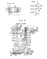
- FIGs. 3-5 show an example in which a right post 20 and a left post 30 are formed in L-shape in the process leading to the present invention.
- FIG. 5 mounting portions 7c and 7d of the shelf 7 are located in the rear.
- the cables 10 that can be accommodated are twice as large in number as the cables 10 accommodated in the constructional form shown in Fig. 4.
- the constructional form shown in Fig. 5 is lower in operability in mounting the shelf 7 than the constructional form shown in Fig. 4, because the spaces 23 and 33 in the front of bent portions 24 and 34 of the right post 20 and the left post 30 respectively are dead spaces for screwing the shelf 7 and a threadably connecting portion is located deep in the rear.
- the right post and the left post are essentially constructed as shown in Fig. 6.
- the casing shown in Fig. 6 has a width L 1 which is smaller than the width L of the casing shown in Fig. 5 by an amount corresponding to the dead spaces 22, 23, 32 and 33 that are eliminated in the constructional form shown therein. Additionally the provision of the shelf mounting portions 41 and 51 in the front of the posts is conducive to improved operability in mounting the shelf 60. What is more important that since the cables 70 are separated from the shelf 60 by the right post 40 and the left post 50, a protection is provided to the cables 70 when the shelves 60 are introduced and removed.
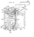
- the casing according to the invention mounts shelves 171 (in Fig. 8 only one shelf 171 is shown but in actual practice a plurality of shelves 171 are arranged vertically in superposed relation) between the left post 120 and the right post 100 as indicated by dash-and-dot lines, each shelf 171 including a plurality of electronic circuit packages 170. Attention is directed to the fact that cables 180 connected to the plurality of electronic circuit packages 170 through connectors extend from above the ceiling board 140 past the outer side of the right post 100 to the front of the shelf 171.
- the side post (right post 100) which constitutes one of the features of the invention has the function of physically separating the cables 180 from the side of the shelf 171, so that a protection can be provided to the cables 180 when the shelves 171 are introduced and removed.
- the shelves 171 are mounted in the casing following completion of assembling thereof.
- the steps to be followed in the process of assembling the casing will now be described by referring to Figs. 8 and 9.
- a screw 234 is tentatively fitted in the threaded opening 191 in the joint bracket 190, and a left panel 230 formed with a groove 231 and mounting openings 232 and 233 has its groove 231 placed on the screw 234, so as to thereby position the left panel 230.
- screws 235 and 234 By tightening screws 235 and 234, the left panel 230 can be secured to the joint plate 210 and the joint bracket 190.
- a front cover 240 formed with mounting openings 214 and 242 is secured to the joint plate 220 and the hinge bracket 200 by screws 243 and 244 respectively.
- a front door 250 formed with mounting openings 251 and 252 is attached to the casing as follows.
- a washer 253 is fitted over the projection 205 formed on the hinge bracket 200 and the projection 205 is fitted in the mounting opening 251 formed in the front door 250.
- a hinge bracket 260 is secured to the joint plate 220 by a screw 262 while a projection 261 on the hinge bracket 260 is inserted in the mounting opening 252 formed in the front door 250.
- the front door 250 is supported for movement between an open position and a closed position about the projections 205 and 261.
- the front door 250 is provided with a handle and locking means is mounted between the front door 250 and the left panel 230.
- a right panel 270 is connected to the joint plate 220 and the hinge bracket 200 in the same manner as described hereinabove by referring to the left panel 230.
- a top plate 280 and a top cover 290 are threadably connected to an upper portion of the front and an upper portion of the back of the ceiling board 140 respectively.
- a convection inducing plate 300 includes a front side fixing portion 301 bent and connected to one side thereof, an inclined surface 302 angled with respect to the horizontal, and a protuberance 303 formed in a suitable position on one side of the plate 300 near the rear of the casing.
- a horizontal end portion 304 extends along the side of the plate 300 toward the rear of the casing at a right angle to the front side fixing portion 301 formed with a threaded opening 305 adapted to be indexed with one of the threaded openings 122 formed in the right post 100 for receiving a screw 306.
- a threaded opening 305 adapted to be indexed with one of the threaded openings 122 formed in the right post 100 for receiving a screw 306.
- a shelf construction of the prior art in the form of a four-sided member has an L-shaped metal fixture attached by welding to one side to serve as a mounting portion for mounting the shelf in the casing, and a handle for withdrawing the shelf is attached to the front of the shelf or lacking in some shelves.
- the shelf construction of the prior art in high in cost and difficult to handle.
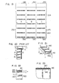
- the side plates 174 and 175 are formed with mounting portions 174a and 175a respectively by cutting and raising the material of the plates 174 and 175, and openings 174b 175b are formed in the mounting portions 174a and 175a respectively for mounting the shelf 171 on the right post 100 and the left post 120. Rectangular openings 174c and 175c formed by cutting and raising the material which are each large enough to receive four fingers serve as handles.
- the shelf according to the invention is low in cost, easy to handle and high in industrial value.
- a pair of upper and lower plates 172' and 173' and a pair of side plates 174' and 175' are of the identical shape and connected together by rivets (or screws) 177.
- a back wiring board 176' supporting connectors 176' is connected to the upper and lower plates 172' and 173' by rivets (or screws) 177.
- the upper and lower plates 172' and 173' are formed with guides 172' and 173'a respectively for guiding the movement of the electronic circuit packages 170 inserted in the shelf 171 and stoppers 172'b and 173'b respectively for shoulders 170a in upper and lower rear ends of the electronic circuit packages 170 to abut thereagainst, so as to regulate the position in which each of the electronic circuit packages 170 is located in the shelf 171.
- the shelf 171 is composed of three standardized parts or plates 172' and 173', plates 174' and 175' and wiring board 176'. In spite of the fact that the shelf 171 is of unitary structure, no ledges are required and the shelf 171 can be directly secured to the posts. Thus the shelf 171 according to the invention is low in cost and has a high industrial value.
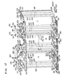
- the casing of a unitary structure shown in Figs. 8 and 9 can be arranged in side-by-side relation in a plurality of number without any trouble in accordance with the scale of the electronic equipment. This particular feature of the invention will be described by referring to Figs. 17-19.
- Figs. 17 and 18 are fragmentary exploded perspective views of the casings showing the process in which they are assembled. Three casings A, B and C are shown as one example.
- each casing is identical in construction to the casing shown in Fig. 8. Therefore, description of the construction of the individual casing will be omitted and the process in which a series of three casings A, B and C are assembled will only be described.
- the joint bracket 190 substantially in the form of a letter U in a lying position formed with the threaded opening 191 and the mounting opening 192 is threadably connected by the screw 193 to the left side of the floor board 150 of the casing A.
- the left post 120 of the casing B is moved close to the right post 100 of the casing A in a manner to be disposed substantially adjacent thereto, and the two casings A and B are interconnected by the hinge bracket 200.
- the hinge bracket 200 are formed with the mounting openings 201-204 and the upwardly extending projection 205, and the floor boards 150 of the casings A and B are formed on the right side and the left side with the mounting openings 151 and 152 in positions corresponding to those of the mounting openings 204 and 201 respectively, so that they are interconnected by the screws 206 (only one screw 206 being shown).
- the casing C is connected to the right side of the casing by the hinge bracket 200, and the hinge bracket 200 is connected to the right side of the floor plate 150 of the casing C. In this way, the casings A, B and C are positioned relative to one another in such a manner that the spacing between the right post 100 and the left post 120 is in the range between 0 and 1 mm.
- the casings A, B and C are connected together in the upper portions thereof as follows.
- the ceiling boards 140 of the casings A, B and C are each formed with threaded openings 141 and 142 and mounting openings 143 and 144, and the casings A and B and B and C are connected together by one of joint plates 310.
- the joint plates 310 are each formed with mounting openings 311 and 312 in positions corresponding to those of the threaded openings 141 and 142 formed in the ceiling boards 140 for connecting the two casings together by screws 313.
- Joint plates 320 are each used for interconnecting the adjacent two casings of the series of casings A, B and C.
- the joint plates 210 and 220 formed with the mounting openings 210-214 are connected by screws 215, 216 and 225, 226 to the left side of the casing A and the right side of the casing B respectively, and the joint plates 320 each formed with mounting openings 321 and 322 are connected between the casings A and B and B and C respectively by screws 323 and 324.
- Aligning of the components of each casing in a vertical direction is effected by means of a liner 330 attached to the floor before the casing is installed with respect to the rear end of the casing, and also by means of a liner 330 inserted from the front side after the casings A, B and C are arranged in side-by-side relation with respect to the front end of the casings. This eliminates the need to carry out installing of the casings from the rear and allows the casings A, B and C to be arranged in front of a wall.
- the front cover 240 formed with the mounting openings 241 and 242 is secured to a joint plate 320 and the hinge bracket 200 by screws 243 and 244 respectively.
- the front door 250 formed with the mounting openings 251 and 252 is connected to each of the casings A, B and C as follows.
- the washer 253 is fitted over the projection 205 formed on the hinge bracket 200 and the projection 205 is fitted in the mounting opening 251 formed in the front door 250, and the projection 261 on the hinge bracket 260 is inserted in the mounting opening 252 formed in the front door 250, so that the hinge bracket 260 can be secured to the joint plate 320 by the screw 262.
- a plurality of openings 254 are formed in the front door 250 (they are not shown in Figs. 9 and 18) for drawing air therethrough into the casing for effecting cooling of the electronic circuit packages 170.
- Figs. 20-23 An embodiment of the invention will now be described by referring to Figs. 20-23 with special reference to the construction of a cable rack. It has hitherto been customary to have cables 10 supported on the cable rack 12 hung from a ceiling 11 of a shed and pass the cables 10 along a side of a communication apparatus casing 13 immediately above the latter, as shown in Fig. 20. Convection inducing plates 14 are mounted above and below a plurality of shelves in the communication apparatus casing 13 for releasing heat to outside.
- the arrangement whereby the cable rack 12 is located near the ceiling 11 of the shed increases the quantity of the material required for fabricating the cable rack 12 and the number of steps for fabricating same.
- the shed itself is required to have a considerably large height, and it is necessary to study the skeleton structure of the ceiling of the shed beforehand and to prepare the shed as a special communication apparatus chamber.
- the communication apparatus casing 13 has hitherto had no ventilating ports formed in a ceiling board 2, so that it is necessary to provide the convection inducing plate 14 above the topmost shelf 7. This has increased the height of the casing, thereby involving an increase in cost.
- the casing is provided with a cable rack serving concurrently as a convection inducing plate in the ceiling.
- Fig. 21 shows the ceiling board 140 according to the invention formed with a multiplicity of rectangular openings 140a for ventilation.
- hot air produced by heat generation in the uppermost shelf 171 flows upwardly through the rectangular openings 140a in the ceiling board 140.
- a convection inducing plate 340 inclined in going from the front side to the rear side to allow a current of air to flow in the indicated direction is mounted on an upper portion of the ceiling board 140.
- the convection inducing plate 340 has a height H which is set at a value such that the current of hot air flows smoothly and no trouble occurs when the cables 180 are bent in passing same along the side of the casing.
- the convection inducing plate 340 is provided with a cable rack 350 substantially in the form of a letter U in a lying position for supporting the cables 180.
- the casing can be installed without any involvement of the ceiling of the shed. Since the cable rack construction allows the cable rack to serve concurrently as a convection inducing plate, the material and the number of steps required in operation can be reduced and assembling can be carried out with increased efficiency.
- the height of the casing can be reduced by an amount corresponding to the thicknesses of the convection inducing plates and cost can be reduced, because the convection inducing plates in the upper portion of the casing can be eliminated.
- the cables can be introduced into the casing according to the invention from below the floor.
Landscapes
- Engineering & Computer Science (AREA)
- Microelectronics & Electronic Packaging (AREA)
- Casings For Electric Apparatus (AREA)
Claims (11)
Applications Claiming Priority (16)
| Application Number | Priority Date | Filing Date | Title |
|---|---|---|---|
| JP1118281U JPS57125592U (de) | 1981-01-30 | 1981-01-30 | |
| JP11182/81U | 1981-01-30 | ||
| JP11877781U JPS5825091U (ja) | 1981-08-12 | 1981-08-12 | 電子ユニツト筐体の構造 |
| JP118777/81U | 1981-08-12 | ||
| JP14413981U JPS5851493U (ja) | 1981-09-30 | 1981-09-30 | 電子ユニツトのシエルフ構造 |
| JP144139/81U | 1981-09-30 | ||
| JP19853381A JPS58100499A (ja) | 1981-12-11 | 1981-12-11 | 電子装置における対流誘導板の取付構造 |
| JP198534/81 | 1981-12-11 | ||
| JP18364281U JPS5889993U (ja) | 1981-12-11 | 1981-12-11 | 電子装置のシエルフ構造 |
| JP183641/81U | 1981-12-11 | ||
| JP198533/81 | 1981-12-11 | ||
| JP183642/81U | 1981-12-11 | ||
| JP19853481A JPS58100498A (ja) | 1981-12-11 | 1981-12-11 | 電子機器の筐体構造 |
| JP18364181U JPS5889999U (ja) | 1981-12-11 | 1981-12-11 | 電子機器架 |
| JP20016981A JPS58101496A (ja) | 1981-12-14 | 1981-12-14 | 電子機器の筐体構造 |
| JP200169/81 | 1981-12-14 |
Publications (3)
| Publication Number | Publication Date |
|---|---|
| EP0057580A2 EP0057580A2 (de) | 1982-08-11 |
| EP0057580A3 EP0057580A3 (en) | 1984-01-18 |
| EP0057580B1 true EP0057580B1 (de) | 1987-07-22 |
Family
ID=27571692
Family Applications (1)
| Application Number | Title | Priority Date | Filing Date |
|---|---|---|---|
| EP82300455A Expired EP0057580B1 (de) | 1981-01-30 | 1982-01-28 | Gestellanordnung für elektronische Anlagen |
Country Status (4)
| Country | Link |
|---|---|
| US (1) | US4553674A (de) |
| EP (1) | EP0057580B1 (de) |
| CA (1) | CA1177151A (de) |
| DE (1) | DE3276845D1 (de) |
Cited By (3)
| Publication number | Priority date | Publication date | Assignee | Title |
|---|---|---|---|---|
| DE4015926C1 (en) * | 1990-05-17 | 1991-10-31 | Siemens Ag, 1000 Berlin Und 8000 Muenchen, De | Magazine for insertable electrical modules - has screening plate and side walls formed from two metal sheets bowed into U=shape |
| CN102933049A (zh) * | 2012-11-15 | 2013-02-13 | 华为技术有限公司 | 一种机柜 |
| EP3280232B1 (de) * | 2016-08-03 | 2023-05-03 | Schneider Electric IT Corporation | Modulares regalsystem |
Families Citing this family (60)
| Publication number | Priority date | Publication date | Assignee | Title |
|---|---|---|---|---|
| CA1198803A (en) * | 1984-01-23 | 1985-12-31 | Frederick T. Cogan | Equipment cabinet |
| AT390598B (de) * | 1984-02-06 | 1990-05-25 | Sticht Walter | Maschinentisch in modulbauweise fuer fertigungseinrichtungen |
| US4641754A (en) * | 1986-01-16 | 1987-02-10 | Homaco, Inc. | Quick connect frame |
| US4894764A (en) * | 1988-04-08 | 1990-01-16 | Omnion Power Engineering Corporation | Modular AC output battery load levelling system |
| US5004107A (en) * | 1989-05-05 | 1991-04-02 | Hendry Mechanical Works | Earthquake braced racks |
| US4966343A (en) * | 1989-07-14 | 1990-10-30 | Knape & Vogt Manufacturing Company | Aesthetic shelving system |
| GB8920852D0 (en) * | 1989-09-14 | 1989-11-01 | Orbitel Mobile Communications | Racking system |
| US4964020A (en) * | 1989-09-27 | 1990-10-16 | At&T Bell Laboratories | Equipment rack |
| DE9013824U1 (de) * | 1990-10-04 | 1992-01-09 | Moll, Hans, 7996 Meckenbeuren | Geräte- und Kabeltrageeinrichtung |
| FR2684513B1 (fr) * | 1991-11-29 | 1994-01-07 | Alcatel Cit | Bati d'equipements electroniques, notamment de telecommunications. |
| GB9214106D0 (en) * | 1992-07-03 | 1992-08-12 | Bicc Plc | Racks for electronic equipment |
| US5323916A (en) * | 1992-12-23 | 1994-06-28 | Newton Instrument Company, Inc. | Unequal flange-type telephone equipment rack adapted for universal application |
| US5279430A (en) * | 1993-05-13 | 1994-01-18 | Unr Industries, Inc. | Storage rack with wire track beam |
| US5360122A (en) * | 1993-05-13 | 1994-11-01 | Unr Industries, Inc. | Storage rack with readily accessible wire track beam |
| JP2693906B2 (ja) * | 1993-12-03 | 1997-12-24 | 日本電気エンジニアリング株式会社 | 通信装置取付枠 |
| US5540339A (en) * | 1994-06-13 | 1996-07-30 | Homaco, Inc. | Telecommunications wall rack |
| GB2294194A (en) * | 1994-10-18 | 1996-04-24 | Vero Electronics Ltd | Rack cabinets |
| US5788087A (en) * | 1996-03-18 | 1998-08-04 | Ortronics, Inc. | Hinged wire management panel assembly |
| US5794795A (en) * | 1996-06-17 | 1998-08-18 | Stemmons; William L. | Framework system for electrical/electronic controls |
| US5819956A (en) * | 1997-02-25 | 1998-10-13 | Sigma-Aldrich Company | Rack for electrical equipment |
| WO1998047335A1 (en) * | 1997-04-16 | 1998-10-22 | Telefonaktiebolaget Lm Ericsson (Publ) | Stackable module for electronic equipment |
| US5983590A (en) * | 1997-05-29 | 1999-11-16 | The Crown Division | Earthquake resistant equipment rack |
| US6006925A (en) * | 1997-06-03 | 1999-12-28 | Hendry Mechanical Works | Equipment rack system |
| DE19811756C1 (de) * | 1998-03-18 | 1999-09-02 | Loh Kg Rittal Werk | Gestell mit einem Gestellrahmen |
| US5971507A (en) * | 1998-05-04 | 1999-10-26 | Lafrance Corporation | Relay rack enclosure |
| US6527351B1 (en) | 1998-06-23 | 2003-03-04 | Hendry Mechanical Works | Equipment mounting racks and cabinets |
| US6561602B1 (en) | 1998-06-23 | 2003-05-13 | Hendry Mechanical Works | Equipment mounting racks and cabinets |
| WO2000022709A1 (en) | 1998-10-09 | 2000-04-20 | American Access Technologies, Inc. | Modular furniture wall system and method for telecommunications equipment and wire management in an open office architecture |
| US6065612A (en) * | 1999-04-23 | 2000-05-23 | Sigma Aldrich Co. | Relay rack with two-way opening door frame |
| US6364439B1 (en) * | 2000-03-31 | 2002-04-02 | Interland, Inc. | Computer storage systems for computer facilities |
| US6557709B2 (en) | 2000-06-29 | 2003-05-06 | Servervault Corp. | Equipment rack accessory for improving equipment mounting |
| CA2430136A1 (en) * | 2000-11-30 | 2002-06-06 | Kevin R. Henderson | Earthquake resistant equipment rack |
| US6523916B2 (en) | 2000-12-22 | 2003-02-25 | Aurora Networks, Inc. | Chassis with repositionable plates |
| US6481582B1 (en) | 2001-06-04 | 2002-11-19 | Cooper Technologies Company | Rack |
| US6502702B1 (en) * | 2001-11-21 | 2003-01-07 | 3Pardata, Inc. | Rack cabinet and method for making same |
| US6675976B2 (en) * | 2002-04-01 | 2004-01-13 | White Rock Networks | Systems and methods for an extension for a nineteen-inch communications switch component rack |
| US6974036B2 (en) * | 2002-04-01 | 2005-12-13 | Viasystems Group, Inc. | Corner post and manufacturing process for making same |
| US7229050B2 (en) * | 2002-11-27 | 2007-06-12 | Hewlett-Packard Development Company, L.P. | Raceway system |
| US7193863B2 (en) * | 2005-01-28 | 2007-03-20 | Honeywell International Inc. | Electronics packaging assembly with parallel circuit boards and a vibration stiffener |
| US7874433B2 (en) | 2005-04-28 | 2011-01-25 | Ortronics, Inc. | Seismically sound rack system |
| US8079481B2 (en) * | 2005-10-28 | 2011-12-20 | International Business Machines Corporation | Integrated frame and central electronic complex structure |
| US20080180004A1 (en) * | 2007-01-31 | 2008-07-31 | Martich Mark E | Modular telecommunications frame and enclosure assembly |
| US8944896B2 (en) * | 2007-02-22 | 2015-02-03 | Tellabs Operations, Inc. | Apparatus, system, and method for venting a chassis |
| SE535066C2 (sv) * | 2008-01-07 | 2012-04-03 | Chatsworth Prod Inc | Vertikal kabelhanteringsanordning |
| US8263867B2 (en) * | 2008-01-07 | 2012-09-11 | Chatsworth Products, Inc. | Cable management accessories |
| WO2009089008A2 (en) * | 2008-01-07 | 2009-07-16 | Corning Cable Systems Llc | Apparatus and method for organizing cables in a cabinet |
| US20090261214A1 (en) * | 2008-04-21 | 2009-10-22 | International Business Machines Corporation | Securing And Managing Electronic Cables In A Modular, Rack-Mounted Computer System |
| US8215498B2 (en) * | 2008-04-30 | 2012-07-10 | Raytheon Company | Modular rack system |
| WO2009143193A2 (en) * | 2008-05-19 | 2009-11-26 | Chatsworth Products, Inc. | Seismically hardened two-post electronic equipment rack |
| US8901438B2 (en) | 2010-09-10 | 2014-12-02 | Chatsworth Products, Inc. | Electronic equipment cabinet structure |
| EP2429272A2 (de) | 2010-09-10 | 2012-03-14 | Chatsworth Products, Inc. | Kabeldurchlaufpaneel für Gehäuse eines elektronischen Geräts |
| US8787023B2 (en) | 2010-09-10 | 2014-07-22 | Chatsworth Products, Inc. | Rail mounting clamp for electronic equipment enclosure |
| US20140196394A1 (en) | 2013-01-11 | 2014-07-17 | Chatsworth Products, Inc. | Modular thermal isolation barrier for data processing equipment structure |
| US9351427B2 (en) | 2013-12-17 | 2016-05-24 | Chatsworth Products, Inc. | Electronic equipment enclosure |
| TWM483461U (zh) * | 2014-03-31 | 2014-08-01 | Super Micro Computer Inc | 可擴充型伺服器機箱 |
| US11818860B1 (en) | 2020-12-15 | 2023-11-14 | Chatsworth Products, Inc. | Frame structure for electronic equipment enclosure |
| US11678456B1 (en) | 2020-12-15 | 2023-06-13 | Chatsworth Products, Inc. | Slidable mounting hardware for electronic equipment enclosure and method for installing same |
| US11622458B1 (en) | 2020-12-15 | 2023-04-04 | Chatsworth Products, Inc. | Brush port assembly and method for installing same |
| US12048108B1 (en) | 2020-12-15 | 2024-07-23 | Chatsworth Products, Inc. | Caster attachment system using mating features |
| US11920392B1 (en) | 2021-02-02 | 2024-03-05 | Chatsworth Products, Inc. | Electrical bonding door hinges |
Family Cites Families (13)
| Publication number | Priority date | Publication date | Assignee | Title |
|---|---|---|---|---|
| US2467828A (en) * | 1946-05-17 | 1949-04-19 | Gen Electric | Switchboard |
| FR1047325A (fr) * | 1951-06-21 | 1953-12-14 | Telecommunications Sa | équipement de centres et postes de matériel pour télécommunications |
| US2959715A (en) * | 1958-10-24 | 1960-11-08 | Leonchick Walter | Instrument rack assembly |
| US3192306A (en) * | 1962-09-26 | 1965-06-29 | Philco Corp | Cooling wall structure for electronic equipment cabinet |
| US3231785A (en) * | 1963-08-12 | 1966-01-25 | Anthony D Calabro | Circuit board mounting device |
| US3387648A (en) * | 1967-02-23 | 1968-06-11 | Navy Usa | Cabinet enclosed recirculation cooling system carried on extensible chassis mountingelectronic modules |
| BE754822A (fr) * | 1969-08-13 | 1971-02-15 | Siemens Ag | Agencement de bati pour appareils electroniques |
| DE7037254U (de) * | 1970-10-08 | 1971-06-09 | Sel Ag | Gestellrahmen |
| DE2211268C3 (de) * | 1972-03-09 | 1978-10-12 | Licentia Patent-Verwaltungs-Gmbh, 6000 Frankfurt | Lüftungsanordnung für Einschübe |
| US4002381A (en) * | 1975-07-31 | 1977-01-11 | Bell Telephone Laboratories, Incorporated | Card mounting assembly |
| DE2635445C3 (de) * | 1976-08-06 | 1979-07-12 | Zweites Deutsches Fernsehen, Anstalt Des Oeffentlichen Rechts, 6500 Mainz | Vorrichtung zur Wärmeabführung aus Geräten |
| US4305114A (en) * | 1979-06-19 | 1981-12-08 | Tokyo Shibaura Denki Kabushiki Kaisha | Motor control center |
| US4353469A (en) * | 1980-04-04 | 1982-10-12 | Western Electric Co., Inc. | Support shelf for printed circuit boards |
-
1982
- 1982-01-28 CA CA000395117A patent/CA1177151A/en not_active Expired
- 1982-01-28 US US06/344,185 patent/US4553674A/en not_active Expired - Fee Related
- 1982-01-28 EP EP82300455A patent/EP0057580B1/de not_active Expired
- 1982-01-28 DE DE8282300455T patent/DE3276845D1/de not_active Expired
Cited By (4)
| Publication number | Priority date | Publication date | Assignee | Title |
|---|---|---|---|---|
| DE4015926C1 (en) * | 1990-05-17 | 1991-10-31 | Siemens Ag, 1000 Berlin Und 8000 Muenchen, De | Magazine for insertable electrical modules - has screening plate and side walls formed from two metal sheets bowed into U=shape |
| CN102933049A (zh) * | 2012-11-15 | 2013-02-13 | 华为技术有限公司 | 一种机柜 |
| CN102933049B (zh) * | 2012-11-15 | 2016-08-10 | 华为技术有限公司 | 一种机柜 |
| EP3280232B1 (de) * | 2016-08-03 | 2023-05-03 | Schneider Electric IT Corporation | Modulares regalsystem |
Also Published As
| Publication number | Publication date |
|---|---|
| CA1177151A (en) | 1984-10-30 |
| EP0057580A3 (en) | 1984-01-18 |
| US4553674A (en) | 1985-11-19 |
| DE3276845D1 (en) | 1987-08-27 |
| EP0057580A2 (de) | 1982-08-11 |
Similar Documents
| Publication | Publication Date | Title |
|---|---|---|
| EP0057580B1 (de) | Gestellanordnung für elektronische Anlagen | |
| US9943003B2 (en) | Electronics cabinet | |
| US10178784B2 (en) | Rail seal for electronic equipment enclosure | |
| US20200275569A1 (en) | Cable pass-through panel for electronic equipment enclosure | |
| US6719382B2 (en) | Chassis with modular repositionable optical feedthrough plates | |
| US4699270A (en) | Modular packaging system | |
| US9301408B2 (en) | Equipment cabinet | |
| EP0333618B1 (de) | Kabelanordnungssystem und Baugruppe | |
| US6075694A (en) | Drive bay for alternately orientable computer chassis | |
| US7239523B1 (en) | Electronic assembly with modular midplane | |
| US20140027392A1 (en) | High-capacity computer rack with rear-accessible side bays | |
| US20080035810A1 (en) | Offset brackets for expanding electronic equipment cabinets | |
| EP0528168A1 (de) | Einteiliges Gehäuse für Elektronik | |
| EP0311702A1 (de) | Einschubgehäuse | |
| EP0577433B1 (de) | Gestelle für elektronische Ausrüstung | |
| EP1344438A2 (de) | Baugruppenträger für von der vorderseite und rückseite eingeschobenen einschübe | |
| JPH06164156A (ja) | 航空機の電気装置用容器のホルダー | |
| EP3349554B1 (de) | Elektronikschrank | |
| US6845206B2 (en) | Interbay housing assembly for fiber optic management systems | |
| US4467399A (en) | Power supply packaging arrangement | |
| JP2567010B2 (ja) | プリント板収納ユニットの構造 | |
| US7002810B1 (en) | System and method for housing electronic equipment in a rack | |
| JP3116828B2 (ja) | ケーブル配線棚 | |
| US7039291B1 (en) | Card rack | |
| CN113423226B (zh) | 一种装配式通信机柜 |
Legal Events
| Date | Code | Title | Description |
|---|---|---|---|
| PUAI | Public reference made under article 153(3) epc to a published international application that has entered the european phase |
Free format text: ORIGINAL CODE: 0009012 |
|
| AK | Designated contracting states |
Designated state(s): DE GB SE |
|
| PUAL | Search report despatched |
Free format text: ORIGINAL CODE: 0009013 |
|
| AK | Designated contracting states |
Designated state(s): DE GB SE |
|
| 17P | Request for examination filed |
Effective date: 19840626 |
|
| GRAA | (expected) grant |
Free format text: ORIGINAL CODE: 0009210 |
|
| AK | Designated contracting states |
Kind code of ref document: B1 Designated state(s): DE GB SE |
|
| PG25 | Lapsed in a contracting state [announced via postgrant information from national office to epo] |
Ref country code: SE Effective date: 19870731 |
|
| REF | Corresponds to: |
Ref document number: 3276845 Country of ref document: DE Date of ref document: 19870827 |
|
| PLBE | No opposition filed within time limit |
Free format text: ORIGINAL CODE: 0009261 |
|
| STAA | Information on the status of an ep patent application or granted ep patent |
Free format text: STATUS: NO OPPOSITION FILED WITHIN TIME LIMIT |
|
| 26N | No opposition filed | ||
| PGFP | Annual fee paid to national office [announced via postgrant information from national office to epo] |
Ref country code: DE Payment date: 19950327 Year of fee payment: 14 |
|
| PGFP | Annual fee paid to national office [announced via postgrant information from national office to epo] |
Ref country code: GB Payment date: 19960119 Year of fee payment: 15 |
|
| PG25 | Lapsed in a contracting state [announced via postgrant information from national office to epo] |
Ref country code: DE Effective date: 19961001 |
|
| PG25 | Lapsed in a contracting state [announced via postgrant information from national office to epo] |
Ref country code: GB Effective date: 19970128 |
|
| GBPC | Gb: european patent ceased through non-payment of renewal fee |
Effective date: 19970128 |