EP0057445B1 - Apparatus and method for froth flotation separation - Google Patents
Apparatus and method for froth flotation separation Download PDFInfo
- Publication number
- EP0057445B1 EP0057445B1 EP19820100636 EP82100636A EP0057445B1 EP 0057445 B1 EP0057445 B1 EP 0057445B1 EP 19820100636 EP19820100636 EP 19820100636 EP 82100636 A EP82100636 A EP 82100636A EP 0057445 B1 EP0057445 B1 EP 0057445B1
- Authority
- EP
- European Patent Office
- Prior art keywords
- spray nozzle
- froth
- tank
- slurry
- input
- Prior art date
- Legal status (The legal status is an assumption and is not a legal conclusion. Google has not performed a legal analysis and makes no representation as to the accuracy of the status listed.)
- Expired
Links
Images


Classifications
-
- B—PERFORMING OPERATIONS; TRANSPORTING
- B03—SEPARATION OF SOLID MATERIALS USING LIQUIDS OR USING PNEUMATIC TABLES OR JIGS; MAGNETIC OR ELECTROSTATIC SEPARATION OF SOLID MATERIALS FROM SOLID MATERIALS OR FLUIDS; SEPARATION BY HIGH-VOLTAGE ELECTRIC FIELDS
- B03B—SEPARATING SOLID MATERIALS USING LIQUIDS OR USING PNEUMATIC TABLES OR JIGS
- B03B9/00—General arrangement of separating plant, e.g. flow sheets
- B03B9/005—General arrangement of separating plant, e.g. flow sheets specially adapted for coal
-
- B—PERFORMING OPERATIONS; TRANSPORTING
- B03—SEPARATION OF SOLID MATERIALS USING LIQUIDS OR USING PNEUMATIC TABLES OR JIGS; MAGNETIC OR ELECTROSTATIC SEPARATION OF SOLID MATERIALS FROM SOLID MATERIALS OR FLUIDS; SEPARATION BY HIGH-VOLTAGE ELECTRIC FIELDS
- B03B—SEPARATING SOLID MATERIALS USING LIQUIDS OR USING PNEUMATIC TABLES OR JIGS
- B03B11/00—Feed or discharge devices integral with washing or wet-separating equipment
-
- B—PERFORMING OPERATIONS; TRANSPORTING
- B03—SEPARATION OF SOLID MATERIALS USING LIQUIDS OR USING PNEUMATIC TABLES OR JIGS; MAGNETIC OR ELECTROSTATIC SEPARATION OF SOLID MATERIALS FROM SOLID MATERIALS OR FLUIDS; SEPARATION BY HIGH-VOLTAGE ELECTRIC FIELDS
- B03D—FLOTATION; DIFFERENTIAL SEDIMENTATION
- B03D1/00—Flotation
- B03D1/14—Flotation machines
- B03D1/1412—Flotation machines with baffles, e.g. at the wall for redirecting settling solids
-
- B—PERFORMING OPERATIONS; TRANSPORTING
- B03—SEPARATION OF SOLID MATERIALS USING LIQUIDS OR USING PNEUMATIC TABLES OR JIGS; MAGNETIC OR ELECTROSTATIC SEPARATION OF SOLID MATERIALS FROM SOLID MATERIALS OR FLUIDS; SEPARATION BY HIGH-VOLTAGE ELECTRIC FIELDS
- B03D—FLOTATION; DIFFERENTIAL SEDIMENTATION
- B03D1/00—Flotation
- B03D1/14—Flotation machines
- B03D1/1443—Feed or discharge mechanisms for flotation tanks
- B03D1/1456—Feed mechanisms for the slurry
-
- B—PERFORMING OPERATIONS; TRANSPORTING
- B03—SEPARATION OF SOLID MATERIALS USING LIQUIDS OR USING PNEUMATIC TABLES OR JIGS; MAGNETIC OR ELECTROSTATIC SEPARATION OF SOLID MATERIALS FROM SOLID MATERIALS OR FLUIDS; SEPARATION BY HIGH-VOLTAGE ELECTRIC FIELDS
- B03D—FLOTATION; DIFFERENTIAL SEDIMENTATION
- B03D1/00—Flotation
- B03D1/14—Flotation machines
- B03D1/1443—Feed or discharge mechanisms for flotation tanks
- B03D1/1462—Discharge mechanisms for the froth
-
- B—PERFORMING OPERATIONS; TRANSPORTING
- B03—SEPARATION OF SOLID MATERIALS USING LIQUIDS OR USING PNEUMATIC TABLES OR JIGS; MAGNETIC OR ELECTROSTATIC SEPARATION OF SOLID MATERIALS FROM SOLID MATERIALS OR FLUIDS; SEPARATION BY HIGH-VOLTAGE ELECTRIC FIELDS
- B03D—FLOTATION; DIFFERENTIAL SEDIMENTATION
- B03D1/00—Flotation
- B03D1/14—Flotation machines
- B03D1/1443—Feed or discharge mechanisms for flotation tanks
- B03D1/1475—Flotation tanks having means for discharging the pulp, e.g. as a bleed stream
-
- B—PERFORMING OPERATIONS; TRANSPORTING
- B03—SEPARATION OF SOLID MATERIALS USING LIQUIDS OR USING PNEUMATIC TABLES OR JIGS; MAGNETIC OR ELECTROSTATIC SEPARATION OF SOLID MATERIALS FROM SOLID MATERIALS OR FLUIDS; SEPARATION BY HIGH-VOLTAGE ELECTRIC FIELDS
- B03D—FLOTATION; DIFFERENTIAL SEDIMENTATION
- B03D1/00—Flotation
- B03D1/14—Flotation machines
- B03D1/1493—Flotation machines with means for establishing a specified flow pattern
-
- C—CHEMISTRY; METALLURGY
- C10—PETROLEUM, GAS OR COKE INDUSTRIES; TECHNICAL GASES CONTAINING CARBON MONOXIDE; FUELS; LUBRICANTS; PEAT
- C10L—FUELS NOT OTHERWISE PROVIDED FOR; NATURAL GAS; SYNTHETIC NATURAL GAS OBTAINED BY PROCESSES NOT COVERED BY SUBCLASSES C10G, C10K; LIQUEFIED PETROLEUM GAS; ADDING MATERIALS TO FUELS OR FIRES TO REDUCE SMOKE OR UNDESIRABLE DEPOSITS OR TO FACILITATE SOOT REMOVAL; FIRELIGHTERS
- C10L9/00—Treating solid fuels to improve their combustion
Definitions
- the present invention relates to apparatus for use in froth flotation separation of components of a slurry having particulate matter therein, the apparatus comprising a flotation tank for containing a liquid and means for creating a froth phase on the surface of said liquid, and further relates to a method for froth flotation separation of components of a slurry having particulate matter therein, in which method there is created a froth phase in which a quantity of particulate matter is floating on a liquid surface and the froth is removed from the surface.
- the described method and apparatus may be usefully applied for beneficiating coal, ground coal particles being separated from impurities associated therewith such as ash and sulfur.
- Coal is an extremely valuable natural resource in the United States, as well as the remainder of the world, because of its relative abundance. It has been estimated that the United States alone has more energy available in the form of coal than in the combined natural resources of petroleum, natural gas, oil shale, and tar sands. Recent energy shortages, together with the availability of abundant coal reserves and the continuing uncertainties regarding the availability of crude oil, have made it imperative that methods for converting coal into a more useful energy source be developed.
- coal is first cleaned of rock and the like, and is then pulverized to a fine grain size of about 0.297 to 0.045 mm (48 to 300 mesh).
- the extended surfaces of the ground coal particles are then rendered hydrophobic and oleophilic by a polymerization reaction.
- the sulfur and mineral ash impurities present in the coal remain hydrophilic and are separated from the treated coal product in a water washing step. This step utilizes oil and water separation techniques, and the coal particles made hydrophobic can float in recovery on a water phase which contains hydrophobic impurities.
- US-A-2 416 066 discloses a froth flotation cell wherein the total discharge area from the nozzles constitutes approximately the area of the pump discharge pipe. See column 2, lines 42 to 44. This disclosure specifically recites a plurality of discrete streams emanating from a header so that the cross-sectional area of such streams will approximate the cross-sectional area of the discharge pipe. Thus, US-A-2 416 066 simply discloses modifying the amount of aeration by either (1) using different numbers of outlets or (2) varying the velocity of the streams. The nozzle of US-A-2 416 066 is merely a short orifice length not designed to cause a diverging spray or a diverging section. Moreover, the prior art jets the slurry into the liquid in the flotation tank through a collar or pipe 20 which extends beneath the liquid surface. Thus, froth which is formed passes beneath the liquid surface and is then recovered.
- An object of the invention is to provide a method and apparatus for use in froth flotation separation of components of a slurry having particulate matter therein which method and apparatus are relatively efficient.
- the invention comprises an apparatus for use in froth flotation separation of components of a slurry having particulate matter therein which is to be separated, the apparatus comprising: a flotation tank (12) for containing a liquid; and means for creating a froth phase (17) on the surface (14) of said liquid, characterized in that said means for creating a froth phase (17) comprises at least one input spray nozzle (16) adapted to cause a diverging spray under pressure and positioned to spray input slurry containing particulate matter through an aeration zone (19) of increasing cross-sectional area into the surface (14) of said liquid to create said froth (17) in which floats a quantity of said particulate matter.
- the method according to the invention comprises a method for froth flotation separation of components of a slurry having particulate matter therein, in which method there is created a froth phase (17) in which a quantity of particular matter is floating on a liquid surface (14); and the froth (17) is removed from the surface, characterized in that the froth (17) is created by spraying an input slurry having particulate matter therein from at least one input spray nozzle (16), wherein said input slurry having particulate matter therein is sprayed from said input spray nozzle (16) under pressure and in a diverging spray pattern through an aeration zone (19) of increasing cross-sectional area into the liquid surface (14).
- the apparatus may further comprise: a collector means positioned in said tank below said at least one input spray nozzle for collecting sinking materials; and at least one recycle spray nozzle positioned above said surface for spraying through an aeration zone into the surface the materials collected by said collector means.
- the or each spray nozzle may, in use of the apparatus, be spaced from said surface of liquid in said tank.
- At least one of said spray nozzles includes a hollow jet member spraying a hollow cone pattern into the liquid surface of the tank.
- the apparatus includes means for supplying said at least one input spray nozzle with slurry in a pressure range of from 0.35 to 2.80 bar (5 to 40 psi).
- the apparatus further includes a skimmer means, adapted to operate along the top of said tank, for skimming froth from the liquid surface.
- a skimmer means adapted to operate along the top of said tank, for skimming froth from the liquid surface.
- Means may be provided for removing materials settling towards the bottom of the tank.
- the method may include the further steps of: collecting sinking materials from the spray of the or each input spray nozzle; and utilizing at least one recycle spray nozzle to respray through an aeration zone into the liquid surface the collected materials, whereby particulate matter therein is recycled and a portion of the recycled material floats as a froth on the liquid surface and is recovered therefrom.
- said step of utilizing a recycle spray nozzle is carried out in proximity to said step of utilizing an input spray nozzle, and further including the step of providing a vertical baffle plate in the liquid between the positions at which the steps of utilizing a recycle spray nozzle and utilizing an input spray nozzle are performed, to provide separation for the sinking materials from both steps.
- the spraying operation creates a froth on the surface of the liquid in which a quantity of the particulate matter is floating, such that the froth containing the particulate matter can be removed from the water surface as a separated product.
- Other components of the slurry and a minor quantity of particulater matter Sind in the liquid bath.
- a collector trough is positioned in the tank below the input spray nozzle(s) for collecting the sinking materials.
- the collected materials are then recycled to at least one recycle spray nozzle positioned above the tank which resprays them through an aeration zone into the liquid surface. Therefore, in this embodiment, the present invention operates in an efficient manner by providing a recycling operation wherein particles which do not float after being sprayed through a primary spray nozzle are recycled to a further spray nozzle to provide a second opportunity for recovery.
- the recycle spray nozzle(s) is positioned in proximity to the primary spray nozzle(s), and a vertical baffle plate is positioned in the tank between the primary and recycle nozzles to provide separation for materials sinking from the sprays of the respective nozzles.
- the or each spray nozzle utilized herein is preferably a hollow jet cone nozzle defining an approximately 30° spray pattern.
- the slurry is preferably supplied to the nozzle in a pressure range of from 0.35 to 2.80 bar (5 to 40 psi) and more preferably in the range of from 1.05 to 1.40 bar (15 to 20 psi).
- the present invention has particular utility to a coal beneficiaation operation for froth flotation separation of a slurry of coal particles and associated impurities.
- the present invention can operate in a manner which is more efficient than prior art arrangements because of the manner of froth generation in which the slurry is sprayed through an aeration zone. Moreover, further efficiency is preferably provided by more effective cleaning of particulate matter such as coal and higher product recoveries by providing that those particles which do not initially float are resprayed into the water surface to promote and provide a high probability of secondary recovery of the product from waste materials.
- a skimmer arrangement having a plurality of spaced skimmer plates depending from a conveyer is arranged along the top of the tank to skim the resultant froth therefrom.
- An upwardly inclined surface extends from the water surface in the tank to a collection tank arranged at one side of the flotation tank, and the skimmer plates skim the froth from the water surface up the inclined surface and into the collection tank.
- the input and recycle spray nozzles are inclined from the vertical in the direction in which the skimmer arrangement operates to direct the flow of froth in that direction along the water surface.
- Settling impurities can be removed from the flotation tank by a circulating arrangement operating near the bottom of the collection tank to remove both water and settling impurities.
- the apparatus and method of the present invention are adapted to the separation of a wide variety of solid-fluid streams by the creation of a solids-containing froth phase, and are suitable for the separation of many types of particulate matter.
- U.S. Patent No. 4,304,573 may be referred to for further details on the chemical processes which are particularly useful in conjunction with the subject invention.
- Fig. 1 illustrates a first embodiment 10 having a flotation tank 12 filled with water to level 14.
- a slurry of finely ground coal particles, associated impurities, and if desired additional additives, such as monomeric chemical initiators, chemical catalysts and fluid hydrocarbons is sprayed through at least one primary spray nozzle 16 positioned at a spaced apart distance above the water level in tank 12.
- two or more nozzles can be used to spray slurry and/or any other desired ingredients into the tank.
- the stream of treated coal is pumped under pressure through a manifold to the spray nozzle 16 wherein the resultant shearing forces spray the coal flocculent slurry as fine droplets such that they are forcefully jetting into the mass of a continuous water bath in tank 12 to form a froth 17.
- High shearing forces are created in nozzle 16, and the dispersed particles forcefully enter the surface of the water and break up the coal-oil- water flocs thereby water-wetting and releasing ash from the interstices between the coal flocs and breaking up the coal flocs so that exposed ash surfaces introduced into the water are separated from the floating coal particles and sink into the water bath.
- the surfaces of the finely divided coal particles now contain air sorbed in the atomized particles, much of which is entrapped by spraying the slurry through an aeration zone 19 such that air is sorbed in the sprayed slurry.
- the combined effects on the treated coal cause the flocculated coal to decrease in apparent density and to float as a froth 17 on the surface of the water bath.
- the hydrophilic ash remains in the bulk water phase, and tends to settle downwardly in tank 12 under the influence of gravity.
- Tank 12 in Fig. 1, 2 and 4 may be a conventional froth flotation tank commercially available from KOM-LINE-Sanderson Engineering Co., Peapack, N.Y. modified as set forth below.
- the flotation tank can also include standard equipment which is not illustrated in the drawings such as a liquid level sensor and control system and a temperature sensing and control system.
- the apparatus operates on a froth generation principle in which the slurry is sprayed through an aeration zone such that substantial quantities of air are sorbed by the sprayed fine droplets of the slurry. Accordingly, air is introduced into the slurry to generate the resultant froth.
- the advantages of this manner of froth generation make the apparatus and method herein particularly applicable to froth flotation separation of slurries which have a substantial proportion of particulate matter therein.
- the coal particles in the floating froth 17 created by nozzle 16 can be removed from the water surface by, e.g., a skimming arrangement 28 in which an endless conveyor belt 30 carries a plurality of spaced skimmer plates 32 depending therefrom.
- the skimmer plates are pivotally attached to the conveyor belt to pivot in two directions relative to the belt, and the bottom run of the belt is positioned above and parallel to the water surface in the tank.
- the plates 32 skim the resultant froth on the water surface in a first direction 34 toward a surface 36, preferably upwardly inclined, extending from the water surface to a collection tank 38 arranged at one side of the flotation tank, such that the skimmer plates 32 skim the froth from the water surface up the surface 36 and into the collection tank 38.
- the waste disposal at the bottom of the tank operates in a direction 40 flowing from an influent stream 42 to the effluent stream 26, while the skimmer arrangement at the top of the tank operates in direction 34, counter to that of the waste disposal arrangement.
- the illustrated embodiment shows a counterflow arrangement, alternative embodiments are contemplated within the scope of the present invention having. e.g., cross and concurrent flows therein.
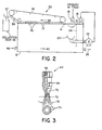
- Fig. 3 is a partially sectional view of one type of commercially available spray nozzle 64 which may be used in conjunction with the systems shown in Fig. 1, 2 and 4.
- a recessed threaded coupling 66 is provided to attach the nozzle to a primary or recycle manifold supplying the nozzle with slurry under pressure.
- the slurry encounters a frustoconical venturi section 68 which accelerates the flow velocity thereof according to the well known venturi effect.
- the slurry then flows through the nozzle aperture having a nominal diameter 70, which in combination with a diverging section 72 defines a hollow cone spray pattern 74 having an encompassing spray angle 76.
- angle 76 is approximately thirty degrees, although other angles which provide the herein contemplated results are included within the scope of this invention.
- Spray nozzle 64 may be a hollow jet nozzle as is commercially available from Spraying Systems Co., Wheaton, Illinois. Of course, it is contemplated herein that other types of nozzles, which function to provide the desired results as hereinbefore described, may also be used.
- the nozzles are preferably constructed of stainless steel, ceramic or other suitable hard metal to avoid erosion by the various particles in the slurry being pumped therethrough.
- the nozzles are preferably supplied with slurry in the supply manifolds at a pressure in the range of 0.35 to 2.80 bar (5 to 40 psi), and more preferably in a pressure range of 1.05 to 1.40 bar (15 to 20 psi).
- Each nozzle 16 is tilted at an angle 6 with respect to a vertical, (i.e., the position of the nozzle relative to the liquid surface level), as shown in Fig. 4, such that it functions to direct the flow of froth in a direction towards the skimmer arrangement 28.
- the angle of incidence 8 does not appear to be critical, and the vertical positioning shown in Fig. 1 may be preferred to create a condition most conducive to agitation and froth generation at the water surface. It appears to be significant that the agitation created by the nozzle sprays define a zone of turbulence extending a limited distance beneath the water surface level. Too much turbulence may actually reduce the amount of frothing produced at the water surface.
- the depth of the turbulence zone may be adjusted by varying the supply pressure of the slurry in the supply manifolds and also the distance of the nozzles above the water surface.
- a zone of turbulence extending 5.08 to 10.16 cm (2 to 4 inch) beneath the water surface produces very good agitation and froth generation, although the distance is dependent on many variables such as the tank size, the medium in the tank, etc. and accordingly may vary considerably in other embodiments.
- a recycling technique is employed to further improve the efficiency relative to prior art arrangements.
- coal particles which do not float after being sprayed through a spray nozzle 16, designated a primary spray nozzle in context with this embodiment are recycled to a further recycle spray nozzle 18 to provide the coal particles with a second opportunity for recovery.
- a collector trough 20, preferably in the form of an open hemispherical pipe is positioned in tank 12 beneath the primary spray nozzle(s) 16 for collecting the sinking materials.
- a pump 22 is coupled to trough 20 and functions to draw settling materials into the trough from which it is pumped under pressure to the recycle spray nozzle(s).
- At least one recycle spray nozzle 18, which may be the same type of nozzle as primary spray nozzle 16, is provided above the tank for respraying into the surface of the water bath the materials collected by the trough such that coal particles collected therein are recycled and a portion of the recycled coal floats as a froth on the water surface an additional time and is recovered.
- the recycled spray nozzle(s) 18 is positioned in proximity to the primary spray nozzle(s) 16, and a vertical baffle plate 24 is positioned in the tank 12 between primary and recycle nozzles to provide separation for materials sinking from the sprays of the respective nozzles.
- further stages of recycling may be provided by adding additional troughs and recycle nozzles in the tank.
- an additional collector means positioned in said tank below said at least one recycle spray nozzle 18 for collecting the sinking materials from its spray, and a further recycle spray nozzle positioned above said tank for spraying through an aeration zone into the liquid surface the materials collected by said additional collector means, whereby two or more stages of recycling are provided.
- This arrangement results in an efficient operation, providing more effective cleaning of the coal and higher product recoveries by providing that coal particles which do not initially float have a high probability of being resprayed onto the water surface to promote secondary recovery of the product from waste materials.
- FIG. 4 illustrates an elevational view of a more detailed illustration of another embodiment of a flotation arrangement 46 persuant to the teachings herein.
- Tank 12 may be a conventional froth flotation tank commercially available from KOM-LINE-Sanderson Engineering Col, Peapack, N.J. modified as set forth below.
- the base of the tank can be supported in a conventional manner by channel and flanged structural members, as illustrated.
- the flotation tank can also include somewhat standard equipment which is not illustrated in the drawings such as a liquid level sensor and control system and a temperature sensing and control system.
- the conveyor system in this embodiment includes a drive roller 48 at one end, driven by a chain or equivalent linkage from a skimmer drive 50 mounted on the tank.
- the other end of the conveyor is defined by an idler roller 52 which in combination with a second idler roller 54 defines a horizontal run for the conveyor along the top of the flotation tank.
- the conveyor belt in this design is defined by two strands of 5.08 cm, double pitch chain with each strand having ninety-six pitches. Twelve skimmer plates are carried by the two chains, with each plate being eight pitches apart on the two conveyor chains.
- the bottom run of the conveyor arrangement is positioned approximately 25,4 cm (ten inches) above the water surface, and each plate depends downwardly from the conveyor chains approximately 25,4 cm (ten inches) to the water surface.
- the skimmer plates carry the coal bearing froth up an inclined surface 36 to a chute 37 through which the froth is directed to a collection tank.
- Trough 20 is in the form of an open hemispherical pipe positioned below the area at which the spray from the primary spray nozzle 16 impinges on the water, and is coupled by lengths of vertical and horizontal conduits 60 and 62 to pump 22, not shown in Fig. 4, which in turn supplies recycle manifold 58 with a slurry at a preferred feed pressure.
- froth flotation separation techniques can be utilized in conjunction with particulate matter such as carbonaceous particles, noncarbonaceous particles, or mixture of both, mine tailings, oil shale, residuals, waste particulates, mineral dressings, graphite, mineral ores, fines, etc.
Description
- The present invention relates to apparatus for use in froth flotation separation of components of a slurry having particulate matter therein, the apparatus comprising a flotation tank for containing a liquid and means for creating a froth phase on the surface of said liquid, and further relates to a method for froth flotation separation of components of a slurry having particulate matter therein, in which method there is created a froth phase in which a quantity of particulate matter is floating on a liquid surface and the froth is removed from the surface.
- The described method and apparatus may be usefully applied for beneficiating coal, ground coal particles being separated from impurities associated therewith such as ash and sulfur.
- Coal is an extremely valuable natural resource in the United States, as well as the remainder of the world, because of its relative abundance. It has been estimated that the United States alone has more energy available in the form of coal than in the combined natural resources of petroleum, natural gas, oil shale, and tar sands. Recent energy shortages, together with the availability of abundant coal reserves and the continuing uncertainties regarding the availability of crude oil, have made it imperative that methods for converting coal into a more useful energy source be developed.
- Known prior art processes for froth flotation separation of a slurry of particulate matter are based on constructions wherein air is introduced into the liquid slurry of the particulate matter as, e.g. through a porous cell bottom or a hollow impeller shaft, thereby producing a surface froth. These prior art methods are relatively inefficient approaches especially when large concentrations of particulate matter are being processed.
- Generally, these techniques are inefficient in providing sufficient contact area between the particulate matter and frothing air. As a result large amounts of energy can be expended in frothing. In addition, froth flotation techniques which permit bubbles to rise in the slurry can tend to trap and carry impurities, such as ash in the froth slurry, and accordingly the resultant beneficiated particulate product can have more impurities therein than necessary.
- Methods have been suggested and are being explored in the beneficiation of coal, i.e., the cleaning of coal of impurities such as ash and sulfur, either prior to burning the coal or after its combustion. In one recently developed technique for beneficiation, termed herein chemical surface treating, raw coal is pulverized to a fine grain size and is then chemically treated. According to this technique the treated coal is then separated from ash and sulfur, and a beneficiated or cleaned coal product is recovered therefrom.
- In further detail, in the heretofore mentioned chemical surface treating process coal is first cleaned of rock and the like, and is then pulverized to a fine grain size of about 0.297 to 0.045 mm (48 to 300 mesh). The extended surfaces of the ground coal particles are then rendered hydrophobic and oleophilic by a polymerization reaction. The sulfur and mineral ash impurities present in the coal remain hydrophilic and are separated from the treated coal product in a water washing step. This step utilizes oil and water separation techniques, and the coal particles made hydrophobic can float in recovery on a water phase which contains hydrophobic impurities.
- US-A-2 416 066 discloses a froth flotation cell wherein the total discharge area from the nozzles constitutes approximately the area of the pump discharge pipe. See column 2,
lines 42 to 44. This disclosure specifically recites a plurality of discrete streams emanating from a header so that the cross-sectional area of such streams will approximate the cross-sectional area of the discharge pipe. Thus, US-A-2 416 066 simply discloses modifying the amount of aeration by either (1) using different numbers of outlets or (2) varying the velocity of the streams. The nozzle of US-A-2 416 066 is merely a short orifice length not designed to cause a diverging spray or a diverging section. Moreover, the prior art jets the slurry into the liquid in the flotation tank through a collar orpipe 20 which extends beneath the liquid surface. Thus, froth which is formed passes beneath the liquid surface and is then recovered. - An object of the invention is to provide a method and apparatus for use in froth flotation separation of components of a slurry having particulate matter therein which method and apparatus are relatively efficient.
- The invention comprises an apparatus for use in froth flotation separation of components of a slurry having particulate matter therein which is to be separated, the apparatus comprising: a flotation tank (12) for containing a liquid; and means for creating a froth phase (17) on the surface (14) of said liquid, characterized in that said means for creating a froth phase (17) comprises at least one input spray nozzle (16) adapted to cause a diverging spray under pressure and positioned to spray input slurry containing particulate matter through an aeration zone (19) of increasing cross-sectional area into the surface (14) of said liquid to create said froth (17) in which floats a quantity of said particulate matter.
- The method according to the invention comprises a method for froth flotation separation of components of a slurry having particulate matter therein, in which method there is created a froth phase (17) in which a quantity of particular matter is floating on a liquid surface (14); and the froth (17) is removed from the surface, characterized in that the froth (17) is created by spraying an input slurry having particulate matter therein from at least one input spray nozzle (16), wherein said input slurry having particulate matter therein is sprayed from said input spray nozzle (16) under pressure and in a diverging spray pattern through an aeration zone (19) of increasing cross-sectional area into the liquid surface (14).
- The apparatus may further comprise: a collector means positioned in said tank below said at least one input spray nozzle for collecting sinking materials; and at least one recycle spray nozzle positioned above said surface for spraying through an aeration zone into the surface the materials collected by said collector means.
- The or each spray nozzle may, in use of the apparatus, be spaced from said surface of liquid in said tank.
- Expediently, at least one of said spray nozzles includes a hollow jet member spraying a hollow cone pattern into the liquid surface of the tank.
- Preferably, the apparatus includes means for supplying said at least one input spray nozzle with slurry in a pressure range of from 0.35 to 2.80 bar (5 to 40 psi).
- Preferably, the apparatus further includes a skimmer means, adapted to operate along the top of said tank, for skimming froth from the liquid surface.
- Means may be provided for removing materials settling towards the bottom of the tank.
- The method may include the further steps of: collecting sinking materials from the spray of the or each input spray nozzle; and utilizing at least one recycle spray nozzle to respray through an aeration zone into the liquid surface the collected materials, whereby particulate matter therein is recycled and a portion of the recycled material floats as a froth on the liquid surface and is recovered therefrom.
- In one embodiment, said step of utilizing a recycle spray nozzle is carried out in proximity to said step of utilizing an input spray nozzle, and further including the step of providing a vertical baffle plate in the liquid between the positions at which the steps of utilizing a recycle spray nozzle and utilizing an input spray nozzle are performed, to provide separation for the sinking materials from both steps.
- As will be apparent, the spraying operation creates a froth on the surface of the liquid in which a quantity of the particulate matter is floating, such that the froth containing the particulate matter can be removed from the water surface as a separated product. Other components of the slurry and a minor quantity of particulater matter sind in the liquid bath.
- Thus, in one embodiment of the present invention, a collector trough is positioned in the tank below the input spray nozzle(s) for collecting the sinking materials. The collected materials are then recycled to at least one recycle spray nozzle positioned above the tank which resprays them through an aeration zone into the liquid surface. Therefore, in this embodiment, the present invention operates in an efficient manner by providing a recycling operation wherein particles which do not float after being sprayed through a primary spray nozzle are recycled to a further spray nozzle to provide a second opportunity for recovery. In a further embodiment, the recycle spray nozzle(s) is positioned in proximity to the primary spray nozzle(s), and a vertical baffle plate is positioned in the tank between the primary and recycle nozzles to provide separation for materials sinking from the sprays of the respective nozzles.
- In accordance with further embodiments of the present invention, the or each spray nozzle utilized herein is preferably a hollow jet cone nozzle defining an approximately 30° spray pattern. Further, the slurry is preferably supplied to the nozzle in a pressure range of from 0.35 to 2.80 bar (5 to 40 psi) and more preferably in the range of from 1.05 to 1.40 bar (15 to 20 psi). Also, the present invention has particular utility to a coal benefication operation for froth flotation separation of a slurry of coal particles and associated impurities.
- The present invention can operate in a manner which is more efficient than prior art arrangements because of the manner of froth generation in which the slurry is sprayed through an aeration zone. Moreover, further efficiency is preferably provided by more effective cleaning of particulate matter such as coal and higher product recoveries by providing that those particles which do not initially float are resprayed into the water surface to promote and provide a high probability of secondary recovery of the product from waste materials.
- In accordance with further details of another embodiment of the present invention, a skimmer arrangement having a plurality of spaced skimmer plates depending from a conveyer is arranged along the top of the tank to skim the resultant froth therefrom. An upwardly inclined surface extends from the water surface in the tank to a collection tank arranged at one side of the flotation tank, and the skimmer plates skim the froth from the water surface up the inclined surface and into the collection tank. Moreover, in one embodiment, the input and recycle spray nozzles are inclined from the vertical in the direction in which the skimmer arrangement operates to direct the flow of froth in that direction along the water surface. Settling impurities can be removed from the flotation tank by a circulating arrangement operating near the bottom of the collection tank to remove both water and settling impurities.
- The present invention will be more readily understood by one skilled in the art with reference to the following detailed description of several preferred embodiments thereof, taken in conjunction with the accompanying drawings wherein like elements are designated by identical reference numerals throughout the several drawings, and in which
- Figure 1 is an elevational view of a schematic exemplary embodiment of a flotation arrangement constructed according to the present invention;
- Figure 2 illustrates an elevational view of another flotation tank utilizing the invention;
- Figure 3 is a partially sectional elevational view of one type of spray nozzle which can be utilized in the embodiments of Figures 1, 2 and 4; and
- Figure 4 illustrates an elevational view of a more detailed embodiment of a flotation tank constructed according to the invention.
- The apparatus and method of the present invention are adapted to the separation of a wide variety of solid-fluid streams by the creation of a solids-containing froth phase, and are suitable for the separation of many types of particulate matter. U.S. Patent No. 4,304,573 may be referred to for further details on the chemical processes which are particularly useful in conjunction with the subject invention.
- The present invention is described herein with reference to a coal beneficiating operation as disclosed, for example, in detail in the aforementioned U.S. Patent. Thus, referring to the drawings herein in greater detail, Fig. 1 illustrates a
first embodiment 10 having aflotation tank 12 filled with water tolevel 14. In operation, a slurry of finely ground coal particles, associated impurities, and if desired additional additives, such as monomeric chemical initiators, chemical catalysts and fluid hydrocarbons is sprayed through at least oneprimary spray nozzle 16 positioned at a spaced apart distance above the water level intank 12. In alternative embodiments, two or more nozzles can be used to spray slurry and/or any other desired ingredients into the tank. - The stream of treated coal is pumped under pressure through a manifold to the
spray nozzle 16 wherein the resultant shearing forces spray the coal flocculent slurry as fine droplets such that they are forcefully jetting into the mass of a continuous water bath intank 12 to form afroth 17. High shearing forces are created innozzle 16, and the dispersed particles forcefully enter the surface of the water and break up the coal-oil- water flocs thereby water-wetting and releasing ash from the interstices between the coal flocs and breaking up the coal flocs so that exposed ash surfaces introduced into the water are separated from the floating coal particles and sink into the water bath. The surfaces of the finely divided coal particles now contain air sorbed in the atomized particles, much of which is entrapped by spraying the slurry through anaeration zone 19 such that air is sorbed in the sprayed slurry. The combined effects on the treated coal cause the flocculated coal to decrease in apparent density and to float as afroth 17 on the surface of the water bath. The hydrophilic ash remains in the bulk water phase, and tends to settle downwardly intank 12 under the influence of gravity.Tank 12 in Fig. 1, 2 and 4 may be a conventional froth flotation tank commercially available from KOM-LINE-Sanderson Engineering Co., Peapack, N.Y. modified as set forth below. The flotation tank can also include standard equipment which is not illustrated in the drawings such as a liquid level sensor and control system and a temperature sensing and control system. - The apparatus operates on a froth generation principle in which the slurry is sprayed through an aeration zone such that substantial quantities of air are sorbed by the sprayed fine droplets of the slurry. Accordingly, air is introduced into the slurry to generate the resultant froth. The advantages of this manner of froth generation make the apparatus and method herein particularly applicable to froth flotation separation of slurries which have a substantial proportion of particulate matter therein.
- The coal particles in the floating
froth 17 created bynozzle 16 can be removed from the water surface by, e.g., a skimmingarrangement 28 in which anendless conveyor belt 30 carries a plurality of spacedskimmer plates 32 depending therefrom. The skimmer plates are pivotally attached to the conveyor belt to pivot in two directions relative to the belt, and the bottom run of the belt is positioned above and parallel to the water surface in the tank. Theplates 32 skim the resultant froth on the water surface in afirst direction 34 toward asurface 36, preferably upwardly inclined, extending from the water surface to acollection tank 38 arranged at one side of the flotation tank, such that theskimmer plates 32 skim the froth from the water surface up thesurface 36 and into thecollection tank 38. - In the arrangement of the disclosed embodiment, the waste disposal at the bottom of the tank operates in a
direction 40 flowing from aninfluent stream 42 to theeffluent stream 26, while the skimmer arrangement at the top of the tank operates indirection 34, counter to that of the waste disposal arrangement. Although the illustrated embodiment shows a counterflow arrangement, alternative embodiments are contemplated within the scope of the present invention having. e.g., cross and concurrent flows therein. - Fig. 3 is a partially sectional view of one type of commercially
available spray nozzle 64 which may be used in conjunction with the systems shown in Fig. 1, 2 and 4. A recessed threadedcoupling 66 is provided to attach the nozzle to a primary or recycle manifold supplying the nozzle with slurry under pressure. The slurry encounters afrustoconical venturi section 68 which accelerates the flow velocity thereof according to the well known venturi effect. The slurry then flows through the nozzle aperture having anominal diameter 70, which in combination with a divergingsection 72 defines a hollow cone spray pattern 74 having an encompassingspray angle 76. In one preferred embodiment of the present invention,angle 76 is approximately thirty degrees, although other angles which provide the herein contemplated results are included within the scope of this invention. - Spray
nozzle 64 may be a hollow jet nozzle as is commercially available from Spraying Systems Co., Wheaton, Illinois. Of course, it is contemplated herein that other types of nozzles, which function to provide the desired results as hereinbefore described, may also be used. The nozzles are preferably constructed of stainless steel, ceramic or other suitable hard metal to avoid erosion by the various particles in the slurry being pumped therethrough. The nozzles are preferably supplied with slurry in the supply manifolds at a pressure in the range of 0.35 to 2.80 bar (5 to 40 psi), and more preferably in a pressure range of 1.05 to 1.40 bar (15 to 20 psi). - Each
nozzle 16 is tilted at an angle 6 with respect to a vertical, (i.e., the position of the nozzle relative to the liquid surface level), as shown in Fig. 4, such that it functions to direct the flow of froth in a direction towards theskimmer arrangement 28. However, the angle of incidence 8 does not appear to be critical, and the vertical positioning shown in Fig. 1 may be preferred to create a condition most conducive to agitation and froth generation at the water surface. It appears to be significant that the agitation created by the nozzle sprays define a zone of turbulence extending a limited distance beneath the water surface level. Too much turbulence may actually reduce the amount of frothing produced at the water surface. Among other means, the depth of the turbulence zone may be adjusted by varying the supply pressure of the slurry in the supply manifolds and also the distance of the nozzles above the water surface. In one operative embodiment, a zone of turbulence extending 5.08 to 10.16 cm (2 to 4 inch) beneath the water surface produces very good agitation and froth generation, although the distance is dependent on many variables such as the tank size, the medium in the tank, etc. and accordingly may vary considerably in other embodiments. - In one embodiment as shown in Fig. 2, a recycling technique is employed to further improve the efficiency relative to prior art arrangements. In the recycling technique, coal particles which do not float after being sprayed through a
spray nozzle 16, designated a primary spray nozzle in context with this embodiment, are recycled to a furtherrecycle spray nozzle 18 to provide the coal particles with a second opportunity for recovery. In this arrangement acollector trough 20, preferably in the form of an open hemispherical pipe, is positioned intank 12 beneath the primary spray nozzle(s) 16 for collecting the sinking materials. Apump 22 is coupled totrough 20 and functions to draw settling materials into the trough from which it is pumped under pressure to the recycle spray nozzle(s). At least onerecycle spray nozzle 18, which may be the same type of nozzle asprimary spray nozzle 16, is provided above the tank for respraying into the surface of the water bath the materials collected by the trough such that coal particles collected therein are recycled and a portion of the recycled coal floats as a froth on the water surface an additional time and is recovered. The recycled spray nozzle(s) 18 is positioned in proximity to the primary spray nozzle(s) 16, and avertical baffle plate 24 is positioned in thetank 12 between primary and recycle nozzles to provide separation for materials sinking from the sprays of the respective nozzles. In alternative embodiments, further stages of recycling may be provided by adding additional troughs and recycle nozzles in the tank. Thus there may be provided an additional collector means positioned in said tank below said at least onerecycle spray nozzle 18 for collecting the sinking materials from its spray, and a further recycle spray nozzle positioned above said tank for spraying through an aeration zone into the liquid surface the materials collected by said additional collector means, whereby two or more stages of recycling are provided. - This arrangement results in an efficient operation, providing more effective cleaning of the coal and higher product recoveries by providing that coal particles which do not initially float have a high probability of being resprayed onto the water surface to promote secondary recovery of the product from waste materials.
- After the recycling operation, the materials which sink from the recycle spray tend to settle downwardly in
tank 12 under the influence of gravity, and are withdrawn in an ash-water stream 26 from the base of the vessel. - Fig. 4 illustrates an elevational view of a more detailed illustration of another embodiment of a
flotation arrangement 46 persuant to the teachings herein.Tank 12 may be a conventional froth flotation tank commercially available from KOM-LINE-Sanderson Engineering Col, Peapack, N.J. modified as set forth below. The base of the tank can be supported in a conventional manner by channel and flanged structural members, as illustrated. The flotation tank can also include somewhat standard equipment which is not illustrated in the drawings such as a liquid level sensor and control system and a temperature sensing and control system. - The conveyor system in this embodiment includes a
drive roller 48 at one end, driven by a chain or equivalent linkage from askimmer drive 50 mounted on the tank. The other end of the conveyor is defined by anidler roller 52 which in combination with asecond idler roller 54 defines a horizontal run for the conveyor along the top of the flotation tank. The conveyor belt in this design is defined by two strands of 5.08 cm, double pitch chain with each strand having ninety-six pitches. Twelve skimmer plates are carried by the two chains, with each plate being eight pitches apart on the two conveyor chains. The bottom run of the conveyor arrangement is positioned approximately 25,4 cm (ten inches) above the water surface, and each plate depends downwardly from the conveyor chains approximately 25,4 cm (ten inches) to the water surface. The skimmer plates carry the coal bearing froth up aninclined surface 36 to achute 37 through which the froth is directed to a collection tank. -
Trough 20 is in the form of an open hemispherical pipe positioned below the area at which the spray from theprimary spray nozzle 16 impinges on the water, and is coupled by lengths of vertical andhorizontal conduits manifold 58 with a slurry at a preferred feed pressure. - While several embodiments and variations of a method and apparatus for froth flotation separation of the components of a slurry have been described in detail herein, it should be apparent that the teachings and disclosure of the present specification will suggest many other embodiments and variations to those skilled in this art.
- Although the froth flotation system has been described in detail herein in the context of a coal beneficiating operation, it is apparent that the disclosure herein has direct applicability to other applications of froth flotation separation technology. For instance, the froth flotation separation techniques disclosed herein can be utilized in conjunction with particulate matter such as carbonaceous particles, noncarbonaceous particles, or mixture of both, mine tailings, oil shale, residuals, waste particulates, mineral dressings, graphite, mineral ores, fines, etc.
Claims (9)
Priority Applications (1)
| Application Number | Priority Date | Filing Date | Title |
|---|---|---|---|
| AT82100636T ATE28730T1 (en) | 1981-01-29 | 1982-01-29 | DEVICE AND PROCESS FOR FOAM FLOTATION SEPARATION. |
Applications Claiming Priority (4)
| Application Number | Priority Date | Filing Date | Title |
|---|---|---|---|
| US230058 | 1981-01-29 | ||
| US230059 | 1981-01-29 | ||
| US06/230,059 US4347127A (en) | 1981-01-29 | 1981-01-29 | Apparatus and method for froth flotation separation of the components of a slurry |
| US06/230,058 US4347126A (en) | 1981-01-29 | 1981-01-29 | Apparatus and method for flotation separation utilizing a spray nozzle |
Publications (3)
| Publication Number | Publication Date |
|---|---|
| EP0057445A2 EP0057445A2 (en) | 1982-08-11 |
| EP0057445A3 EP0057445A3 (en) | 1984-08-01 |
| EP0057445B1 true EP0057445B1 (en) | 1987-08-05 |
Family
ID=26923873
Family Applications (1)
| Application Number | Title | Priority Date | Filing Date |
|---|---|---|---|
| EP19820100636 Expired EP0057445B1 (en) | 1981-01-29 | 1982-01-29 | Apparatus and method for froth flotation separation |
Country Status (4)
| Country | Link |
|---|---|
| EP (1) | EP0057445B1 (en) |
| AU (1) | AU546684B2 (en) |
| CA (1) | CA1181873A (en) |
| DE (1) | DE3276901D1 (en) |
Families Citing this family (6)
| Publication number | Priority date | Publication date | Assignee | Title |
|---|---|---|---|---|
| US4514291A (en) * | 1983-05-18 | 1985-04-30 | The Standard Oil Company | Apparatus and method for flotation separation utilizing an improved spiral spray nozzle |
| AU561931B2 (en) * | 1983-06-16 | 1987-05-21 | Board Of Control Of Michigan Technological University | Column froth flotation |
| US4605494A (en) * | 1984-09-14 | 1986-08-12 | Sohio Alternate Energy Development Co. | Multistream, multiproduct, pressure manipulation beneficiation arrangement |
| US4597858A (en) * | 1984-09-14 | 1986-07-01 | Sohio Alternate Energy Development Co. | Multistream, multiproduct beneficiation arrangement |
| AU601698B2 (en) * | 1985-11-27 | 1990-09-20 | Standard Oil Company, The | Apparatus and method for froth flotation |
| CN114411445B (en) * | 2022-01-25 | 2023-01-03 | 临沂大瑞木业有限公司 | Production equipment and method of composite impregnated paper |
Family Cites Families (5)
| Publication number | Priority date | Publication date | Assignee | Title |
|---|---|---|---|---|
| DE311196C (en) * | ||||
| US2416066A (en) * | 1944-05-19 | 1947-02-18 | Donald S Phelps | Froth flotation cell |
| US2983377A (en) * | 1956-07-24 | 1961-05-09 | Shirriff Horsey Corp Ltd | Process and apparatus for cleaning fruit pulp |
| US3015396A (en) * | 1959-12-03 | 1962-01-02 | Chain Belt Co | Apparatus for flotation of suspended material |
| US3326373A (en) * | 1964-05-07 | 1967-06-20 | Swift & Co | Ore concentration |
-
1982
- 1982-01-26 AU AU79853/82A patent/AU546684B2/en not_active Ceased
- 1982-01-29 CA CA000395233A patent/CA1181873A/en not_active Expired
- 1982-01-29 EP EP19820100636 patent/EP0057445B1/en not_active Expired
- 1982-01-29 DE DE8282100636T patent/DE3276901D1/en not_active Expired
Also Published As
| Publication number | Publication date |
|---|---|
| AU546684B2 (en) | 1985-09-12 |
| CA1181873A (en) | 1985-01-29 |
| EP0057445A2 (en) | 1982-08-11 |
| DE3276901D1 (en) | 1987-09-10 |
| AU7985382A (en) | 1982-08-05 |
| EP0057445A3 (en) | 1984-08-01 |
Similar Documents
| Publication | Publication Date | Title |
|---|---|---|
| US4347127A (en) | Apparatus and method for froth flotation separation of the components of a slurry | |
| US4347126A (en) | Apparatus and method for flotation separation utilizing a spray nozzle | |
| US4514291A (en) | Apparatus and method for flotation separation utilizing an improved spiral spray nozzle | |
| US4650567A (en) | Apparatus and method for flotation separation utilizing an improved spiral spray nozzle | |
| US4659458A (en) | Apparatus and method for froth flotation employing rotatably mounted spraying and skimming means | |
| US4436617A (en) | Froth flotation ore beneficiation process utilizing enhanced gasification and flow techniques | |
| CA2656212C (en) | Flotation cell | |
| CA2661579A1 (en) | Helical conduit hydrocyclone methods | |
| US4966687A (en) | Method and apparatus for column flotation of mineral matter | |
| US4913805A (en) | Apparatus and method for froth flotation | |
| EP0057445B1 (en) | Apparatus and method for froth flotation separation | |
| AU601698B2 (en) | Apparatus and method for froth flotation | |
| US4950390A (en) | Apparatus and method for froth flotation | |
| US4737282A (en) | Apparatus for separating sand and oil from a waste water stream | |
| US3326373A (en) | Ore concentration | |
| US4597858A (en) | Multistream, multiproduct beneficiation arrangement | |
| CA1181874A (en) | Apparatus and method for froth flotation separation of the components of a slurry | |
| USH458H (en) | Pressure-reducing spray nozzle and use thereof in a froth flotation method | |
| US4605494A (en) | Multistream, multiproduct, pressure manipulation beneficiation arrangement | |
| JPH06154656A (en) | Floating separator for suspended matter in liquid | |
| USH871H (en) | Froth flotation of mineral ores | |
| Jera et al. | A Review on Froth Washing in Flotation. Minerals 2022, 12, 1462 |
Legal Events
| Date | Code | Title | Description |
|---|---|---|---|
| PUAI | Public reference made under article 153(3) epc to a published international application that has entered the european phase |
Free format text: ORIGINAL CODE: 0009012 |
|
| AK | Designated contracting states |
Designated state(s): AT BE CH DE FR GB IT LU NL SE |
|
| PUAL | Search report despatched |
Free format text: ORIGINAL CODE: 0009013 |
|
| AK | Designated contracting states |
Designated state(s): AT BE CH DE FR GB IT LI LU NL SE |
|
| 17P | Request for examination filed |
Effective date: 19841128 |
|
| GRAA | (expected) grant |
Free format text: ORIGINAL CODE: 0009210 |
|
| RAP1 | Party data changed (applicant data changed or rights of an application transferred) |
Owner name: THE STANDARD OIL COMPANY |
|
| AK | Designated contracting states |
Kind code of ref document: B1 Designated state(s): AT BE CH DE FR GB IT LI LU NL SE |
|
| REF | Corresponds to: |
Ref document number: 28730 Country of ref document: AT Date of ref document: 19870815 Kind code of ref document: T |
|
| REF | Corresponds to: |
Ref document number: 3276901 Country of ref document: DE Date of ref document: 19870910 |
|
| ET | Fr: translation filed | ||
| ITF | It: translation for a ep patent filed |
Owner name: MODIANO & ASSOCIATI S.R.L. |
|
| PG25 | Lapsed in a contracting state [announced via postgrant information from national office to epo] |
Ref country code: LU Free format text: LAPSE BECAUSE OF NON-PAYMENT OF DUE FEES Effective date: 19880131 |
|
| PLBE | No opposition filed within time limit |
Free format text: ORIGINAL CODE: 0009261 |
|
| STAA | Information on the status of an ep patent application or granted ep patent |
Free format text: STATUS: NO OPPOSITION FILED WITHIN TIME LIMIT |
|
| 26N | No opposition filed | ||
| PGFP | Annual fee paid to national office [announced via postgrant information from national office to epo] |
Ref country code: LU Payment date: 19890109 Year of fee payment: 8 |
|
| PGFP | Annual fee paid to national office [announced via postgrant information from national office to epo] |
Ref country code: AT Payment date: 19891222 Year of fee payment: 9 |
|
| PGFP | Annual fee paid to national office [announced via postgrant information from national office to epo] |
Ref country code: SE Payment date: 19891229 Year of fee payment: 9 |
|
| PGFP | Annual fee paid to national office [announced via postgrant information from national office to epo] |
Ref country code: GB Payment date: 19891231 Year of fee payment: 9 |
|
| PGFP | Annual fee paid to national office [announced via postgrant information from national office to epo] |
Ref country code: FR Payment date: 19900115 Year of fee payment: 9 |
|
| PGFP | Annual fee paid to national office [announced via postgrant information from national office to epo] |
Ref country code: DE Payment date: 19900125 Year of fee payment: 9 |
|
| ITTA | It: last paid annual fee | ||
| PGFP | Annual fee paid to national office [announced via postgrant information from national office to epo] |
Ref country code: NL Payment date: 19900131 Year of fee payment: 9 |
|
| PGFP | Annual fee paid to national office [announced via postgrant information from national office to epo] |
Ref country code: CH Payment date: 19900330 Year of fee payment: 9 |
|
| PGFP | Annual fee paid to national office [announced via postgrant information from national office to epo] |
Ref country code: BE Payment date: 19900509 Year of fee payment: 9 |
|
| PG25 | Lapsed in a contracting state [announced via postgrant information from national office to epo] |
Ref country code: GB Effective date: 19910129 Ref country code: AT Effective date: 19910129 |
|
| PG25 | Lapsed in a contracting state [announced via postgrant information from national office to epo] |
Ref country code: SE Effective date: 19910130 |
|
| PG25 | Lapsed in a contracting state [announced via postgrant information from national office to epo] |
Ref country code: LI Effective date: 19910131 Ref country code: CH Effective date: 19910131 Ref country code: BE Effective date: 19910131 |
|
| PG25 | Lapsed in a contracting state [announced via postgrant information from national office to epo] |
Ref country code: NL Effective date: 19910801 |
|
| NLV4 | Nl: lapsed or anulled due to non-payment of the annual fee | ||
| GBPC | Gb: european patent ceased through non-payment of renewal fee | ||
| PG25 | Lapsed in a contracting state [announced via postgrant information from national office to epo] |
Ref country code: FR Effective date: 19910930 |
|
| REG | Reference to a national code |
Ref country code: CH Ref legal event code: PL |
|
| PG25 | Lapsed in a contracting state [announced via postgrant information from national office to epo] |
Ref country code: DE Effective date: 19911001 |
|
| REG | Reference to a national code |
Ref country code: FR Ref legal event code: ST |
|
| EUG | Se: european patent has lapsed |
Ref document number: 82100636.8 Effective date: 19910910 |