EP0057094A2 - Curling iron - Google Patents
Curling iron Download PDFInfo
- Publication number
- EP0057094A2 EP0057094A2 EP82300328A EP82300328A EP0057094A2 EP 0057094 A2 EP0057094 A2 EP 0057094A2 EP 82300328 A EP82300328 A EP 82300328A EP 82300328 A EP82300328 A EP 82300328A EP 0057094 A2 EP0057094 A2 EP 0057094A2
- Authority
- EP
- European Patent Office
- Prior art keywords
- actuators
- bristles
- brushes
- bars
- movement
- Prior art date
- Legal status (The legal status is an assumption and is not a legal conclusion. Google has not performed a legal analysis and makes no representation as to the accuracy of the status listed.)
- Withdrawn
Links
Images

Classifications
-
- A—HUMAN NECESSITIES
- A45—HAND OR TRAVELLING ARTICLES
- A45D—HAIRDRESSING OR SHAVING EQUIPMENT; EQUIPMENT FOR COSMETICS OR COSMETIC TREATMENTS, e.g. FOR MANICURING OR PEDICURING
- A45D1/00—Curling-tongs, i.e. tongs for use when hot; Curling-irons, i.e. irons for use when hot; Accessories therefor
- A45D1/18—Curling-tongs, i.e. tongs for use when hot; Curling-irons, i.e. irons for use when hot; Accessories therefor with combs
Definitions
- the present invention relates to curling irons with a handle and bristles.
- rows of bristles extending the length of the barrel may be provided.
- Use of bristles fixedly secured to the barrel requires that the section of hair be unrolled to remove the barrel from the hair, and if the hair is still hot when unrolled, the hair cools at least partially in an unrolled and straightened position. Consequently, the resultant curl is not as tight as desired. Even if the hair were allowed to cool completely before unrolling, which is unlikely due to the unreasonably long time which would be required for setting a head of hair, once the cooled curl is unrolled, it is not resilient enough to return to its fully curled position.
- the pulling and resulting time delay can be damaging to the hair, reduce the tightness of the curl and be extremely frustrating to the user of the curling iron.
- a curling iron which has bristles which may be retracted into the barrel so that the barrel can be conveniently removed from the hair without disturbing the curl. Since hair styling requires that curls be of a limited diameter, preferably about two centimetres or less, the space available within the barrel for the bristles when retracted and for the mechanism for retracting them, is limited. The problem is further complicated by the requirement that the bristles be of sufficient length to catch a minimum quantity of hair to achieve an acceptable curl thickness.
- a curling iron having a handle, a generally elongate body attached at one end to the handle, and bristles extending in a generally radially outward direction at the body, characterised in that the said body is tubular having a radial side wall with a plurality of wall openings, at least one selectively operable member is disposed within the body for reciprocating longitudinal movement, and conversion means are arranged to coact with the said member to convert reciprocating longitudinal movement of the member into generally radially reciprocating movement of the bristles through the wall openings, whereby the longitudinal movement of the member results in retraction or extension of the bristles.
- a curling iron having an elongate body equipped with substantially radially disposed bristles and, at one end, a handle, characterised in that the said body is substantially hollow, the bristles are so mounted within the body as to be movable radially outwardly and inwardly through side wall openings provided in the body, and at least one member operable by a user is disposed within the body for back and forth longitudinal movement relative to the body, such movement by the said member being converted by means provided within the body into substantially radial movement of the bristles whereby the bristles can be extended from or retracted into the body by operation of the said member.
- a preferred embodiment of the present invention resides in a hair curling iron having a handle, a tubular body secured by its one end to the handle and with a radial side wall containing a plurality of wall openings, a plurality of retractable brushes disposed within the body with bristles extending in a generally radially outward direction, at least one selectively operable member disposed within the body for reciprocating longitudinal movement, and conversion means co-acting with the member for converting its reciprocating longitudinal movement into generally radially reciprocating movement of the bristles through the side wall openings to accomplish retraction or extension of the brushes.
- this curling iron includes a plurality of slide actuators positioned toward each end of the body and disposed to move longitudinally with respect to the body for slidably engaging the brushes at a preselected angle for causing their movement in a similar generally radial direction in response to similarly directed longitudinal movement of the actuators.
- the curling iron also includes means for simultaneously moving the actuators in a similar longitudinal direction for retraction or extension of the brushes, and brush guides for restraining the longitudinal movement of the brushes with respect to the body as the actuators are moved.
- the actuators are fixedly secured to supports positioned substantially within the body toward its distal ends and beyond the brushes, and the supports are disposed to move longitudinally with respect to the body. Also included are means for manually controlling the movement of the actuators in one longitudinal direction for retracting the bristles through the wall openings, and means for automatically moving the actuators in an other longitudinal direction for extending the bristles after once retracted.
- the actuators include pins
- the means for simultaneously moving the actuators include a member slidably disposed within the body, in longitudinal coaxial alignment with it, which extends between and is fixedly secured to the supports.
- the brushes are comprised of a plurality bars to which the bristles are rigidly secured, and the brush guides are positioned within and fixedly secured to the body and extend in a generally radial direction for slidably engaging the bars.
- the bars are positioned radially offset from the longitudinal axis of the body to provide increased travel of the brushes by avoiding their contact with the member.
- the means for manually controlling the movement of the actuators for extension of the bristles comprises a sleeve extending external to the body and engaging the supports for moving them toward one end of the body, and the means for automatically moving the actuators for retraction of the bristles comprises a resilient member for applying a biasing force on the supports for moving them toward the other end of the body after the bristles have been retracted.
- Offset lugs projecting laterally outward from the bars slidably engage the actuator pins away from the bristles to avoid their interference with the bristles.
- the support toward the handle end of the body has a plurality of arms extending generally radially outward beyond the side wall for attachment of the actuator pins external to the side wall.
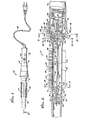
- the curling iron 10 includes a handle 12 and an elongate, tubular body 14 having a first distal end 16, a second distal end 18 and a radial side wall 20.
- the body 14 is rigidly attached along its second distal end 18 to the handle 12, and forms a longitudinal extension of the handle.
- a pair of insulated electrical resistive heating elements 22 are enclosed within the body 14 and extend along substantially the entire length of the body for conduction heating of the body.
- a section of hair (not shown) is wound around the body 14 by rotating the curling iron 10 about its longitudinal axis, and the heat transferred to the hair upon heating of the body promotes setting of the hair into a curl.
- the side wall 20 has an exterior wall surface 24 which the hair contacts as it is wound around the body 14, and an interior wall surface 26 against which the heating elements 22 are held by a pair of retainers 28 formed as an integral part of the body 14.
- the heating elements 22 are spaced apart along the interior wall surface 26, generally opposite each other, to provide more uniform heating of the body 14.
- Application of electrical power to the heating elements 22, and hence the heat applied to the body 14 and the hair, is controlled by an electrical switch 30 mounted in the handle 12 for convenient operation by the user of the curling iron.
- An indicator light 31 is also mounted in the handle, adjacent to the switch 30 and is illuminated when the switch 30 is placed in an "ON" position. Electrical power is supplied to the switch 30 through an electrical cord 32 extending from the handle 12 and equipped with a suitable plug.
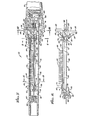
- the curling iron 10 includes a plurality of retractable brushes 34 extending longitudinally within the body 14, a plurality of first end slide actuators 36 positioned toward the first distal end 16 and disposed to -move longitudinally with respect to the body 14 and to slidably engage the brushes 34 at a preselected angle a for causing their movement in a generally radial direction in response to the longitudinal movement of the first end actuators 36, a plurality of second end slide actuators 38 positioned toward the second distal end 18 and disposed to move longitudinally with respect to the body 14 and to slidably engaging the brushes 34 at the preselected angle a for causing their movement in a generally radial direction in response to the longitidinal movement of the second end actuators 38, and a tie member 40 slidably disposed within the body 14 and connecting the first and second end actuators 36 and 38 together to provide for their simultaneous longitudinal movement.
- the actuators 36 and 38 are so oriented, with respect to each other, as: to cause similarly directed radial movement of the brushes 34 when the actuators are moved in the same longitudinal direction, and when simultaneously moved in the same direction, the actuators 36 and 38 cause extension or retraction of the brushes 34.
- the body 14 has a plurality of wall opening 42 spaced along its length, and the brushes 34 are comprised of elongate bars 44 with bristles 46 rigidly secured thereto and extending in a generally radially outward direction for reciprocating movement through the wall opening 42.
- a plurality of bar guides 48 is provided. Thcbar guides 48 extend in a generally radial direction, and are fixedly secured to the body 14 and slidably engage the bars 44.
- the first and second end slide actuators 36 and 38 are fixedly secured to and carried by first and second end supports 50 and 52, respectively, which maintain the angular orientation of the actuators 36 and 38 with respect'to the brushes 34.
- the first end support 50 is positioned within the body 14 toward its first distal end 16 and beyond the brushes 34, and is longitudinally movable within the body 14.
- the second end support 52 is positioned substantially within the body 14 toward its second distal end 18 and beyond the brushes 34, and is longitudinally movable within the body 14.
- the tie member 40 holds the first and second end supports 50 and 52 in a fixed spatial relationship to each other, and causes these supports, and hence the actuators 36 and 38, to move simultaneously and in the same longitudinal direction in response to a longitudinal force applied to the second end support 52.
- Retraction of the bristles 46 through the wall openings 42 is accomplished by movement of a manually operable control member 54, extending externally of the body 14 for easy grasping by the userof the curling iron.
- the control member 54 engages the second end support 52 and can apply a longitudinal force to it which is directed away from the brushes 34.
- the supports 50 and 52 move toward the second distal end 18, and therefore so also do the actuators 36 and 38, and the angular relationship of the actuators to the brushes 34 converts this longitudinal movement into a radially inwardly directed force on the brushes, causing their retraction into the body 14 to the position illustrated in Fig.7.
- the bristles 46 are automatically extending by the action of a resilient member 56 positioned within the body 14 to apply a longitudinally inward (i.e. towards the brushes 34) biasing force on the second end support 50.
- This biasing force moves the supports 50 and 52 toward the first distal end 16 and returns the actuators 36 and 38 to a position with the bristles 46 fully extended through the wall openings 42 (Fig.2).
- the resilient member 56 in the embodiment shown is a helical compression spring.
- the tie member 40 is comprised of a rod 58 positioned within the body 14, in longitudinal coaxial alignment with it, for longitudinal reciprocating movement.
- the rod 58 has a first end rod portion 60 slidably supported by a first end guide block 62 which is fixedly secured to the body toward its first distal end 16 and beyond the first end support 50, and a second end rod portion 64 slidably supported by a second end guide block 66 which is fixedly secured to the body 14 toward its second distal end 18 and beyond the second end support 52.
- the guide blocks 62 and 66 also serve to maintain the longitudinal alignment of the rod 58 within the body 14.
- the rod 58 carries the supports 50 and 52, which are rigidly attached to the rod sufficiently inward from the guide blocks 62 and 66 to allow for the full longitudinal movement of the supports necessary to retract and extend the brushes 34.
- the resilient member 56 is trapped between the guide block 66 and the support 52 and is coaxial with the rod portion 64.
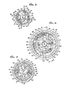
- the curling iron 10 has four brushes 34, each having a single row of bristles 46 of a predetermined length longitudinally and uniformly spaced along one of the bars 44 and extending at a substantially right angle to the bar.
- the brushes 34 are symmetrically positioned around the longitudinal axis of the body 14, and the bristles 46 of any one brush extend in an opposite or an orthogonal direction relative to the bristles of the other three brushes.
- the wall openings 42 through which the bristles 46 move, are aligned and sized to correspond with the bristles and permit their unrestricted extension and retraction through the side wall 20. It is noted that although the illustrated embodiment has only a single bristle extending through each wall opening, the wall openings could be sized to accommodate several bristles or an entire brush.
- the bars 44 are positioned and move radially offset from the longitudinal axis of the body by a distance sufficient to prevent the bars from contacting the rod 58 as the brushes are retracted. With each of the bars 44 similarly offset in a uniform manner, the radially inward travel of the bars is not limited by the presence of the rod 58 at the radial centre of body 14, and the travel continues until the bars strike against each other at the position shown in Figs. 8, 9 and 10.
- the bars When viewed from the second distal end 18 of the body 14, as in Figs. 3 and 8, and using the bristles 46 of any one of the bars 44 to prescribe an imaginary vertical reference line, with the radially outward end of the bristles indicating the upward direction, the bars are radially offset to the right of the rod 58. It will be appreciated, however, that the bars 44 could be offset to the left of the rod 58 with equal effectiveness, so long as all bars of the curling iron were similarly offset.
- the bars 44 are generally rectangular in cross-section with each having an upper side 68, facing in a generally radially outward direction, to which the bristles 46 are secured, and an opposite lower side 70, facing in a generally radially inward direction.
- Connecting the upper and lower sides 68 and 70 is an inner side 72 which faces towards the rod 58 when the bars 44 are in the fully retracted position.
- the lower side 70 of each of the bars 44 abuts the inner side 72 of one of the adjacent bars, with the inner side serving as a stop.
- the bars 44 have a first end bar portion 74 and a second end bar portion 76, indicated in Figs. 2, 7 and 11, which slidably engage the first and second end slide actuators 36 and 38 respectively.
- the actuators 36 and 38 comprise pins extending longitudinally inward from the first and second end supports 50 and 52 toward the bars 44 at the preselected angle a relative to the bars.
- the first and second end bar portions 74 and 76 are provided with angled guide holes 78 correspondingly sized and angled to slidably receive the pins.
- a single pin is used at each of the end portions 74 and 76 of the bars 44.
- the bars 44 may be manufactured of zinc or aluminium, and the pins of high tempered steel with a polished surface.
- the actuators 36 and 38 are, of course, also radially offset from the longitudinal axis of the body 14.
- the actuators 36 and 38 engage offset lugs 80 formed as an integral part of the bar at its first and second end bar portions 74 and 76. From Figs.
- the lugs 80 extend laterally from the bar 44 to the radially outward side of the bristles 46, at a substantially right angle to the bristles, and have the angled guide holes 78 formed therein.
- the first end actuator 36 for each bar extends from the support at a point located below the most radially inward travel of the bar experienced, to a point near the interior wall surface 26 of the body 14.
- the second end support 52 To support the second end slide actuators 38 at a point located above the most radially outward travel of the bars 44, which is a bar positioned immediately adjacent to the interior wall surface 26 of the body 14, the second end support 52 has a plurality of arms 82 rigidly secured thereto and extending in a generally radially outward direction beyond the side wall 20 through a plurality of slots 84 in the body (see Figs. 5 and 10).
- the second end actuators 38 are secured to the arms 82 at a point exterior to the body 14, and the slots 84 are sized to permit longitudinal movement of the arms as the second end support 52 moves for extension and retraction of the brushes 34. (compare Figs. 2 and 7).
- the bar guides 48 which restrain longitudinal movement of the bars 44 as the brushes are extended or retracted, comprise pins extending substantially perpendicular to the bars 44.
- the second end bar portion 76 of each of the bars 44 is provided with a single guide hole 86 positioned and sized to slidably receive one of the pins.
- the pins used as the bar guides 48 may be manufactured of high tempered steel with a polished surface to reduce friction.
- the control member 54 used to retract the brushes 34 comprises a collar 88 slidably disposed around the body 14 and the handle 12, in the vicinity of their attachment to each other.
- the collar 88 is outwardly flared at its longitudinally inward end to provide an annular gripping surface 90 to facilitate grasping of the collar by the user of the curling iron.
- the interior of the collar 88 has a plurality of shoulders 92 facing longitudinally outward and positioned to cooperate with the arms 82 of the second end support 52., The shoulders 92 engage the arms 82, and transmit the longitudinally outward force necessary to retract the brushes 34.
- the resilient member 56 returns the brushes 34 to the extended position, the arms 82 apply a longitudinally inward force on the shoulders 92 and return the collar 88 to its original position.
- Rotation of the collar 88 about the body 14 and handle 12 is prevented by providing one of the shoulders 92 with tabs 94 positioned to each side of the shoulder to limit the rotational movement of the collar relative to the second end support 52.
- the second end support 52 as part of the entire assembly including the supports 50 and 52, the actuators 36 and 38 and the bars 44, is prevented from rotating within the body 14 by the bar guides 48 which are rigidly secured to the body 14.
- an insulated sleeve 96 extends around the body and covers a portion of the body longitudinally inward from the collar. The sleeve 96 also extends partially under the collar 88 to cover that section of the body exposed when the collar is moved for retraction of the brushes 34.
- the sleeve 96 also serves as a stop in cooperation with a pair of catches 98, formed as an integral part of the collar 88, which engage the sleeve and limit the longitudinally inward movement of the collar, as is needed with the collar being under the biasing force of the resilient member 56.
- the sleeve 96 is fixedly secured to the body 14 by the bar guides 48 which extend outward beyond body and into the sleeve.
- the resilient member 56 comprises a coil spring positioned along the longitudinal axis of the body 14 around the rod 58, and extending between the second end support 52 and the second end guide block 66.
- a recess 100 is provided in the second end support 52 to hold one end of the spring in place.
Landscapes
- Brushes (AREA)
Abstract
A curling iron (10) has a tubular body (14) with bristles (46) and a handle (12). The bristles (46) are fixed in four bars (44) within the body (14) and extend outward for reciprocating movement through wall openings (42). Four actuator pins (36,38) fixed to each of two supports (50,52) extend at an angle (a) to slidably engage the bars (44) and move them radially when the supports (50,52) are moved together longitudinally by a slidably mounted tie rod (58). Four guide pins (48) fixed to the body (14) restrain longitudinal movement of the bars (44). An external manually operable sleeve (54) on the body (14) engages one support (52) for moving the supports (50,52) for retraction of the bristles (46), and a spring (100) biases the support (52) for automatic return to a position with the bristles (46) extended.
Description
- The present invention relates to curling irons with a handle and bristles.
- It has long been known that the application of heat to hair will promote its setting, and conventional curling irons use this principle to set hair in curls. A section of hair to be curled is wound around a barrel of the curling iron, and the barrel is heated or a burst of steam or hot air is applied to heat the hair and set the curl.
- To facilitate grasping and winding of the section of hair, rows of bristles extending the length of the barrel may be provided. Use of bristles fixedly secured to the barrel, however, requires that the section of hair be unrolled to remove the barrel from the hair, and if the hair is still hot when unrolled, the hair cools at least partially in an unrolled and straightened position. Consequently, the resultant curl is not as tight as desired. Even if the hair were allowed to cool completely before unrolling, which is unlikely due to the unreasonably long time which would be required for setting a head of hair, once the cooled curl is unrolled, it is not resilient enough to return to its fully curled position.
- A further problem encountered when unrolling the hair, either in a hot or cold state, is that the bristles tend to snag the hair and cause it to rewind about the barrel in a reverse direction. The pulling and resulting time delay can be damaging to the hair, reduce the tightness of the curl and be extremely frustrating to the user of the curling iron.
- In an attempt to solve these problems, a curling iron is here proposed which has bristles which may be retracted into the barrel so that the barrel can be conveniently removed from the hair without disturbing the curl. Since hair styling requires that curls be of a limited diameter, preferably about two centimetres or less, the space available within the barrel for the bristles when retracted and for the mechanism for retracting them, is limited. The problem is further complicated by the requirement that the bristles be of sufficient length to catch a minimum quantity of hair to achieve an acceptable curl thickness.
- According to one aspect of the present invention there is provided a curling iron having a handle, a generally elongate body attached at one end to the handle, and bristles extending in a generally radially outward direction at the body, characterised in that the said body is tubular having a radial side wall with a plurality of wall openings, at least one selectively operable member is disposed within the body for reciprocating longitudinal movement, and conversion means are arranged to coact with the said member to convert reciprocating longitudinal movement of the member into generally radially reciprocating movement of the bristles through the wall openings, whereby the longitudinal movement of the member results in retraction or extension of the bristles.
- According to another aspect of the invention there is provided a curling iron having an elongate body equipped with substantially radially disposed bristles and, at one end, a handle, characterised in that the said body is substantially hollow, the bristles are so mounted within the body as to be movable radially outwardly and inwardly through side wall openings provided in the body, and at least one member operable by a user is disposed within the body for back and forth longitudinal movement relative to the body, such movement by the said member being converted by means provided within the body into substantially radial movement of the bristles whereby the bristles can be extended from or retracted into the body by operation of the said member.
- It will be appreciated that there has been a significant need for a hair curling iron with fully retractable-brushes which can fit within a barrel of limited diameter and have bristles of a sufficient length for the curling iron to be effectively and efficiently used in the creation of popular hair styles.
- A preferred embodiment of the present invention resides in a hair curling iron having a handle, a tubular body secured by its one end to the handle and with a radial side wall containing a plurality of wall openings, a plurality of retractable brushes disposed within the body with bristles extending in a generally radially outward direction, at least one selectively operable member disposed within the body for reciprocating longitudinal movement, and conversion means co-acting with the member for converting its reciprocating longitudinal movement into generally radially reciprocating movement of the bristles through the side wall openings to accomplish retraction or extension of the brushes.
- Basically, and in general terms, this curling iron includes a plurality of slide actuators positioned toward each end of the body and disposed to move longitudinally with respect to the body for slidably engaging the brushes at a preselected angle for causing their movement in a similar generally radial direction in response to similarly directed longitudinal movement of the actuators.. The curling iron also includes means for simultaneously moving the actuators in a similar longitudinal direction for retraction or extension of the brushes, and brush guides for restraining the longitudinal movement of the brushes with respect to the body as the actuators are moved.
- The actuators are fixedly secured to supports positioned substantially within the body toward its distal ends and beyond the brushes, and the supports are disposed to move longitudinally with respect to the body. Also included are means for manually controlling the movement of the actuators in one longitudinal direction for retracting the bristles through the wall openings, and means for automatically moving the actuators in an other longitudinal direction for extending the bristles after once retracted.
- More specifically, in the presently preferred embodiment of the invention, the actuators include pins, and the means for simultaneously moving the actuators include a member slidably disposed within the body, in longitudinal coaxial alignment with it, which extends between and is fixedly secured to the supports. The brushes are comprised of a plurality bars to which the bristles are rigidly secured, and the brush guides are positioned within and fixedly secured to the body and extend in a generally radial direction for slidably engaging the bars. The bars are positioned radially offset from the longitudinal axis of the body to provide increased travel of the brushes by avoiding their contact with the member.
- The means for manually controlling the movement of the actuators for extension of the bristles comprises a sleeve extending external to the body and engaging the supports for moving them toward one end of the body, and the means for automatically moving the actuators for retraction of the bristles comprises a resilient member for applying a biasing force on the supports for moving them toward the other end of the body after the bristles have been retracted.
- Offset lugs projecting laterally outward from the bars slidably engage the actuator pins away from the bristles to avoid their interference with the bristles. The support toward the handle end of the body has a plurality of arms extending generally radially outward beyond the side wall for attachment of the actuator pins external to the side wall.
- The invention will now be described in more detail, solely by way of example, with reference to the accompanying drawings, in which:-
- Fig. 1 is a plan view of a curling iron embodying the present invention;
- Fig. 2 is an enlarged, fragmentary, sectional view taken substantially along the lines 2-2 of Fig.l, showing the curling iron with its brushes in a fully extended position;
- Fig. 3 is an enlarged, fragmentary, sectional view taken substantially along the line 3-3 of Fig.2;
- Fig. 4 is an enlarged, sectional view taken substantially alonj the line 4-4 of Fig.2;
- Fig. 5 is an enlarged, sectional view taken substantially along the line 5-5 of Fig. 2;
- Fig. 6 is an enlarged, sectional view taken substantially along the line 6-6 of Fig. 2, and indicating more specifically the line along which Fig. 2 is taken;
- Fig. 7 is the same view of the curling iron as shown in Fig. 2, but with the brushes in a fully retracted position;
- Fig. 8 is an enlarged, sectional view taken substantially along the line 8-8 of Fig.7;
- Fig. 9 is an enlarged, sectional view taken substantially along the line 9-9 of Fig. 7;
- Fig. 10 is an enlarged, sectional view taken substantially along the line 10-10 of Fig. 7; and
- Fig. 11 is an enlarged, fragmentary, perspective view of the actuation mechanism of the curling iron shown in Fig.l.
- In the drawings an embodiment of the present invention is shown in the form of a hair curling iron indicated generally by a
reference numeral 10. It will be seen from Figs. 1 and 2 that thecurling iron 10 includes ahandle 12 and an elongate,tubular body 14 having a firstdistal end 16, a seconddistal end 18 and aradial side wall 20. Thebody 14 is rigidly attached along its seconddistal end 18 to thehandle 12, and forms a longitudinal extension of the handle. - A pair of insulated electrical resistive heating elements 22 (see Figs. 3 to 6) are enclosed within the
body 14 and extend along substantially the entire length of the body for conduction heating of the body. - In use a section of hair (not shown) is wound around the
body 14 by rotating thecurling iron 10 about its longitudinal axis, and the heat transferred to the hair upon heating of the body promotes setting of the hair into a curl. Theside wall 20 has anexterior wall surface 24 which the hair contacts as it is wound around thebody 14, and aninterior wall surface 26 against which theheating elements 22 are held by a pair ofretainers 28 formed as an integral part of thebody 14. Theheating elements 22 are spaced apart along theinterior wall surface 26, generally opposite each other, to provide more uniform heating of thebody 14. Application of electrical power to theheating elements 22, and hence the heat applied to thebody 14 and the hair, is controlled by anelectrical switch 30 mounted in thehandle 12 for convenient operation by the user of the curling iron. Anindicator light 31 is also mounted in the handle, adjacent to theswitch 30 and is illuminated when theswitch 30 is placed in an "ON" position. Electrical power is supplied to theswitch 30 through an electrical cord 32 extending from thehandle 12 and equipped with a suitable plug. - In accordance with the invention, the
curling iron 10 includes a plurality ofretractable brushes 34 extending longitudinally within thebody 14, a plurality of firstend slide actuators 36 positioned toward the firstdistal end 16 and disposed to -move longitudinally with respect to thebody 14 and to slidably engage thebrushes 34 at a preselected angle a for causing their movement in a generally radial direction in response to the longitudinal movement of thefirst end actuators 36, a plurality of secondend slide actuators 38 positioned toward the seconddistal end 18 and disposed to move longitudinally with respect to thebody 14 and to slidably engaging thebrushes 34 at the preselected angle a for causing their movement in a generally radial direction in response to the longitidinal movement of thesecond end actuators 38, and atie member 40 slidably disposed within thebody 14 and connecting the first andsecond end actuators actuators brushes 34 when the actuators are moved in the same longitudinal direction, and when simultaneously moved in the same direction, theactuators brushes 34. - The
body 14 has a plurality of wall opening 42 spaced along its length, and thebrushes 34 are comprised ofelongate bars 44 withbristles 46 rigidly secured thereto and extending in a generally radially outward direction for reciprocating movement through the wall opening 42. To maintain proper alignment of thebristles 46 within thewall openings 42 and restrain longitudinal movement of thebars 44 as theactuators 36 and 37 are moved longitudinally for extension and retraction of thebrushes 34, a plurality ofbar guides 48 is provided. Thcbarguides 48 extend in a generally radial direction, and are fixedly secured to thebody 14 and slidably engage thebars 44. - The first and second
end slide actuators actuators brushes 34. Thefirst end support 50 is positioned within thebody 14 toward its firstdistal end 16 and beyond thebrushes 34, and is longitudinally movable within thebody 14. Thesecond end support 52 is positioned substantially within thebody 14 toward its seconddistal end 18 and beyond thebrushes 34, and is longitudinally movable within thebody 14. Thetie member 40 holds the first and second end supports 50 and 52 in a fixed spatial relationship to each other, and causes these supports, and hence theactuators second end support 52. - Retraction of the
bristles 46 through thewall openings 42 is accomplished by movement of a manuallyoperable control member 54, extending externally of thebody 14 for easy grasping by the userof the curling iron. Thecontrol member 54 engages thesecond end support 52 and can apply a longitudinal force to it which is directed away from thebrushes 34. In response to this force, the supports 50 and 52 move toward the seconddistal end 18, and therefore so also do theactuators brushes 34 converts this longitudinal movement into a radially inwardly directed force on the brushes, causing their retraction into thebody 14 to the position illustrated in Fig.7. - When the
control member 54 is released by the user, thebristles 46 are automatically extending by the action of a resilient member 56 positioned within thebody 14 to apply a longitudinally inward (i.e. towards the brushes 34) biasing force on thesecond end support 50. This biasing force moves thesupports distal end 16 and returns theactuators bristles 46 fully extended through the wall openings 42 (Fig.2). The resilient member 56 in the embodiment shown is a helical compression spring. - The
tie member 40 is comprised of arod 58 positioned within thebody 14, in longitudinal coaxial alignment with it, for longitudinal reciprocating movement. Therod 58 has a firstend rod portion 60 slidably supported by a first end guide block 62 which is fixedly secured to the body toward its firstdistal end 16 and beyond thefirst end support 50, and a secondend rod portion 64 slidably supported by a secondend guide block 66 which is fixedly secured to thebody 14 toward its seconddistal end 18 and beyond thesecond end support 52. The guide blocks 62 and 66 also serve to maintain the longitudinal alignment of therod 58 within thebody 14. Therod 58 carries thesupports brushes 34. The resilient member 56 is trapped between theguide block 66 and thesupport 52 and is coaxial with therod portion 64. - In the illustrated embodiment of the invention shown in Figs. 1-11, the curling
iron 10 has fourbrushes 34, each having a single row ofbristles 46 of a predetermined length longitudinally and uniformly spaced along one of thebars 44 and extending at a substantially right angle to the bar. Thebrushes 34 are symmetrically positioned around the longitudinal axis of thebody 14, and thebristles 46 of any one brush extend in an opposite or an orthogonal direction relative to the bristles of the other three brushes. - The
wall openings 42, through which thebristles 46 move, are aligned and sized to correspond with the bristles and permit their unrestricted extension and retraction through theside wall 20. It is noted that although the illustrated embodiment has only a single bristle extending through each wall opening, the wall openings could be sized to accommodate several bristles or an entire brush. - As shown in Figs. 3 and 8, to maximize the travel of the
brushes 34 within thebody 14, and hence the length of thebristles 46 which can be fully retracted into the body clear of itsexterior wall surface 24, thebars 44 are positioned and move radially offset from the longitudinal axis of the body by a distance sufficient to prevent the bars from contacting therod 58 as the brushes are retracted. With each of thebars 44 similarly offset in a uniform manner, the radially inward travel of the bars is not limited by the presence of therod 58 at the radial centre ofbody 14, and the travel continues until the bars strike against each other at the position shown in Figs. 8, 9 and 10. - When viewed from the second
distal end 18 of thebody 14, as in Figs. 3 and 8, and using thebristles 46 of any one of thebars 44 to prescribe an imaginary vertical reference line, with the radially outward end of the bristles indicating the upward direction, the bars are radially offset to the right of therod 58. It will be appreciated, however, that thebars 44 could be offset to the left of therod 58 with equal effectiveness, so long as all bars of the curling iron were similarly offset. - As shown in Fig.9, the
bars 44 are generally rectangular in cross-section with each having anupper side 68, facing in a generally radially outward direction, to which thebristles 46 are secured, and an oppositelower side 70, facing in a generally radially inward direction. Connecting the upper andlower sides inner side 72 which faces towards therod 58 when thebars 44 are in the fully retracted position. When in such a position, thelower side 70 of each of thebars 44 abuts theinner side 72 of one of the adjacent bars, with the inner side serving as a stop. - The
bars 44 have a firstend bar portion 74 and a secondend bar portion 76, indicated in Figs. 2, 7 and 11, which slidably engage the first and secondend slide actuators actuators bars 44 at the preselected angle a relative to the bars. The first and secondend bar portions end portions bars 44. To reduce friction, thebars 44 may be manufactured of zinc or aluminium, and the pins of high tempered steel with a polished surface. - To moye the
bars 44 in the radially offset manner mentioned above, theactuators body 14. To avoid interference of thefirst end actuators 36 with thebristles 46 secured along the firstend bar portion 74 of thebars 44, without necessitating lengthening of the bars and hence thebody 14, theactuators lugs 80 formed as an integral part of the bar at its first and secondend bar portions lugs 80 extend laterally from thebar 44 to the radially outward side of thebristles 46, at a substantially right angle to the bristles, and have the angled guide holes 78 formed therein. - From Fig.7 it will be seen that, to avoid interference of the
first end support 50 with the travel of thebars 44 when the bars move in a generally radially inward direction for full retraction of thebrushes 34, thefirst end actuator 36 for each bar extends from the support at a point located below the most radially inward travel of the bar experienced, to a point near theinterior wall surface 26 of thebody 14. From Fig.2 it will be seen that, to avoid interference of thesecond end support 52 with the travel of thebars 44 when the bars move in a generally radially outward direction for full extension of thebrushes 34, thesecond end actuator 38 for each bar extends from the support at a point located above the most radially outward travel of the bar experienced, to a point adjacent to the rod 58.-By eliminating interference of thesupports bars 44, the maximum travel of the bars, and hence retractable bristle length, is achieved. - To support the second
end slide actuators 38 at a point located above the most radially outward travel of thebars 44, which is a bar positioned immediately adjacent to theinterior wall surface 26 of thebody 14, thesecond end support 52 has a plurality ofarms 82 rigidly secured thereto and extending in a generally radially outward direction beyond theside wall 20 through a plurality ofslots 84 in the body (see Figs. 5 and 10). Thesecond end actuators 38 are secured to thearms 82 at a point exterior to thebody 14, and theslots 84 are sized to permit longitudinal movement of the arms as thesecond end support 52 moves for extension and retraction of thebrushes 34. (compare Figs. 2 and 7). - The bar guides 48, which restrain longitudinal movement of the
bars 44 as the brushes are extended or retracted, comprise pins extending substantially perpendicular to thebars 44. The secondend bar portion 76 of each of thebars 44 is provided with asingle guide hole 86 positioned and sized to slidably receive one of the pins. As with the pins comprising theactuators - The
control member 54 used to retract thebrushes 34 comprises acollar 88 slidably disposed around thebody 14 and thehandle 12, in the vicinity of their attachment to each other. Thecollar 88 is outwardly flared at its longitudinally inward end to provide an annulargripping surface 90 to facilitate grasping of the collar by the user of the curling iron. As shown in Fig.6, the interior of thecollar 88 has a plurality ofshoulders 92 facing longitudinally outward and positioned to cooperate with thearms 82 of the second end support 52., Theshoulders 92 engage thearms 82, and transmit the longitudinally outward force necessary to retract thebrushes 34. When the resilient member 56 returns thebrushes 34 to the extended position, thearms 82 apply a longitudinally inward force on theshoulders 92 and return thecollar 88 to its original position. - Rotation of the
collar 88 about thebody 14 and handle 12 is prevented by providing one of theshoulders 92 withtabs 94 positioned to each side of the shoulder to limit the rotational movement of the collar relative to thesecond end support 52. Thesecond end support 52, as part of the entire assembly including thesupports actuators bars 44, is prevented from rotating within thebody 14 by the bar guides 48 which are rigidly secured to thebody 14. - To reduce the likelihood of the user of the curling iron touching the
heated body 14 when grasping the grippingsurface 90 of thecollar 88 for retraction of thebrushes 34, aninsulated sleeve 96 extends around the body and covers a portion of the body longitudinally inward from the collar. Thesleeve 96 also extends partially under thecollar 88 to cover that section of the body exposed when the collar is moved for retraction of thebrushes 34. - The
sleeve 96 also serves as a stop in cooperation with a pair ofcatches 98, formed as an integral part of thecollar 88, which engage the sleeve and limit the longitudinally inward movement of the collar, as is needed with the collar being under the biasing force of the resilient member 56. Thesleeve 96 is fixedly secured to thebody 14 by the bar guides 48 which extend outward beyond body and into the sleeve. - The resilient member 56 comprises a coil spring positioned along the longitudinal axis of the
body 14 around therod 58, and extending between thesecond end support 52 and the secondend guide block 66. Arecess 100 is provided in thesecond end support 52 to hold one end of the spring in place. - From the foregoing, it will be appreciated that the embodiment of the invention described hereinbefore for the purposes of illustration, provides a hair curling iron with fully and substantially radially retractable bristles which fit within a body of limited diameter while still providing bristles with a sufficient length. It will also be appreciated that, although a specific embodiment of the invention has been described herein for purposes of illustration, various modifications may be made without departing from the scope of the invention.
Claims (21)
1. A curling iron having a handle (12), a generally elongate body (14) attached at one end to the handle (12), and bristles (46) extending in a generally radially outward direction at the body (14), characterised in that the said body (14) is tubular haying a radial side wall (20)with a plurality of wall openings (42), the bristles (46) are secured in a plurality of brushes (.341 extending longitudinally within the body (14), at least one selectively operable member (40) is disposed within the body (14) for reciprocating longitudinal movement, and conversion means (36, 38, 50, 52) are arranged to coact with the said member (40) to convert reciprocating longitudinal movement of the member (40) into generally radially reciprocating movement of the bristles (46) through the wall openings (42), whereby the longitudinal movement of the member (40) results in retraction or extension of the bristles (46).
2. A curling iron according to claim 1, characterised in that the conversion means includes a plurality of first end slide actuators (36) which are positioned toward an end (16) of the body (14) remote from the handle (12) and are disposed to move longitudinally with. respect to the body (14), the actuators (36) slidably engaging the brushes (34) at a preselected angle (a) for causing movement of the brushes (34) in a generally radial direction in response to the longitudinal movement of the actuators (36), and a plurality of second end slide actuators (38) which are positioned toward an end (18) of the body (14) adjacent to the handle (12) and are disposed to move longitudinally with respect to the body (14), these actuators slidably engaging the brushes (34) at the said preselected angle (a) for causing movement of the brushes (34) in a generally radial direction in response to the longitudinal movement of the actuators (38), the second end actuators (38) being positioned to cause similarly directed radial movement of the brushes (34) as caused by the first end actuators (36) when the first and second end actuators (36,38) move in a similar longitudinal direction.
3. A curling iron according to claim 2f characterised in that the conversion means further includes brush guides (48) for restraining the longitudinal movement of the brushes (34) with respect to the body (14) .
4. A curling iron according to claim 2 or 3, wherein the said member (40) is slidably disposed within the body (14) and fixedly secured to the first and second end slide actuators (36,38) for simultaneously moving the first and second end actuators (36,38) in the said similar longitudinal direction.
5. A curling iron having a handle (12), a generally elongate body (14) attached at one end to the handle (12), and bristles (46) extending in a generally radially outward direction at the body (14), characterised in that the bristles (46) are secured in a plurality of brushes (34) extending longitudinally within the body (14) and extend through wall openings (42) in a radial side wall (20) of the body (14) which is tubular, a plurality of first end slide actuators (36) are positioned toward an end (16) of the body (14) remote from the handle (12) and are disposed to move longitudinally with respect to the body (14), the actuators (36) slidably engaging the brushes (34) at a preselected angle (a) for causing movement of the brushes (34) in a generally radial direction in response to the longitudinal movement of the actuators (36), a plurality of second end slide actuators (.38) are positioned toward an end (18) of the body (14) adjacent to the handle (12) and disposed to move longitudinally with respect to the body (14), these actuators (38) slidably engaging the brushes (34) at the said preselected angle (α) for causing movement of the brushes (34) in a generally radial direction in response to the longitudinal movement of the actuators (38), the second end actuators (38) being positioned to cause similarly directed radial movement of the brushes (34) as caused by the first end actuators (36) when the first and second end actuators (36, 38) move in a similar longitudinal direction, and means (40) for simultaneously moving the first and second end actuators (36,38) in the said similar longitudinal direction, whereby movement of the first and second end actuators (36,38) results in retraction or extension of the bristles (46).
6. A curling iron according to claim 5, characterised by including means (48) for restraining longitudinal movement of the brushes (34) with respect to the body (14) as the first and second end actuators (36,38) move.
7. A curling iron according to claim 5 or 6, characterised by including means C54) for manually controlling movement of the first and second end actuators (36,38) in one longitudinal direction for retraction of the bristles (46) through the wall openings (42).
8. A curling iron according to claim 7, characterised by including means (100) for automatically moving the first and second actuators (36,38) in another longitudinal direction for extension of the bristles (46) through the wall openings (42) after being retracted.
9. A curling iron having a handle (12), a generally elongate body (14) attached at one end to the handle (12), and bristles (46) extending in a generally radially outward direction at the body (14), characterised in that the body (14) is tubular and has a radial side wall (20) with a plurality of wall openings (42), a plurality of brushes (34) in which the bristles (46) are secured extend longitudinally within the body (14), a first end support (50) is positioned within the body (14) toward an end (16) of the body (14) remote from the handle (12) and beyond the brushes (34), and disposed to move longitudinally with respect to the body (14), a plurality of first end slide actuators (36) are fixedly secured to the first end support (50) and slidably engage the brushes (34) at a preselected angle (a) relative to the brushes (34) for causing movement of the brushes (34) in a generally radial direction in response to the longitudinal movement of the first end support (5), a second end support (52) is positioned substantially within the body (14) toward an end (18) of the body (14) adjacent to the handle (12) and beyond the brushes (34), and disposed to move longitudinally with respectto the body (14), a plurality of second end slide actuators (38) are fixedly secured to the second support (52) and slidably engage the brushes (34) at a preselected angle (a) relative to the brushes (34) for causing movement of the brushes (34) in a generally radial direction in response to the longitudinal movement of the second end support (52), the second end actuators (38) being positioned to cause similarly directed radial movement of the brushes (34) as caused by the first end actuators (36) when the first and second end supports (50,52) move in a similar longitudinal direction; and means (40) for simultaneously moving the first and second end supports (50,52) in the said similar longitudinal direction.
10. A curling iron according to claim 9, characterised by including means (48) for restraining longitudinal movement of the brushes (34) with respect to the body (14) as the first and second end supports (50,52) move.
11. A curling iron according to claim 9 or 10, characterised by including means (54) for manually controlling movement of the first and second end supports (50, 52) in one longitudinal direction for retracting the bristles (46) through the wall openings (42).
12. A curling iron according to claim 11, characterised by including means (100) for automatically moving the first and second end supports (50,52) in another longitudinal direction for extension of the bristles (46) through the wall openings (42) after being retracted.
13. A curling iron comprising a handle (12) and an elongate body (14) equipped with bristles (46), characterised by:
an elongated, generally tubular body (14) having a first distal end (16), a second distal end (18) and a radial side wall (20), the body (14) being rigidly attached at the second end (18) to the handle (12), and the side wall (20) having a plurality of wall openings (42);
a plurality of elongated bars (44) extending longitudinally within the body (14), the bars (44) having bristles (46) of a predetermined length rigidly secured thereto and extending in a generally radially outward direction for reciprocating movement through the wall openings (42);
a first end support (50) positioned within the body (14) toward the first distal end (16) and beyond the bars (44), and disposed to move longitudinally with respect to the body (14);
a plurality of first end actuator pins (36) fixedly secured to the first end support (50) and extending longitudinally inward toward the bars (44) at a preselected angle (a) relative to the bars (44), the pins (36) slidably engaging the adjacent end portions (74) of the bars (44) for moving the bars (44) in a generally radial direction in response to the longitudinal movement of the first end support (50);
a second end support (52) positioned substantially within the body (14) toward the second distal end (18) and beyond the bars (44), and disposed to move longitudinally with respect to the body (44);
a plurality of second end actuator pins (38) fixedly secured to the second end support (52) and extending longitudinally inward toward the bars (44) at a preselected angle (a) relative to the bars (44), these pins (38) slidably engaging the adjacent end portions (.76) of the bars (44) for moving the bars (44) in a generally radial direction in response to the longitudinal movement of the second end support (52), the second end actuator pins (38) being positioned to cause similarly directed radial movement of the bars (44) as caused by the first end actuator pins (36) when the first and second end supports (50,52) move in a similar longitudinal direction; and
means (40) for simultaneously moving the first and second end supports (50,52) in the said similar longitudinal direction.
14. A curling iron according to claim 13, characterised in that the means (40) for simultaneously moving the first and second end supports (50,52) includes a member (58) slidably disposed within the body (14), in longitudinal, coaxial alignment with the body (14), the said member (58) extending between and fixedly secured to the first and second end supports (50,52).
15. A curling iron according to claim 14, characterised in that the bars (44) are positioned radially offset from the longitudinal axis of the body 44, whereby the radially inward movement of the bars (44) is not limited by the presence of the said member (58).
16. A curling iron according to claim 13 or 14 or 15, characterised by including bar guides (48) positioned within and fixedly secured to the body (14), the guides (48) extending in a generally radial direction for slidably engaging and restraining longitudinal movement of the bars (44).
17. A curling iron according to claim 13 or 14 or 15 or 16, characterised by including a manually operable collar (54) extending external to the body (14) and engaging the second end support (52) for moving the first and second end supports (50,52) toward the second distal end (18) for retraction of the bristles (46) through the wall openings (42).
18. A curling iron according to claim 17, characterised by including a resilient member (100) for applying a biasing force on the second end support (52) directed toward the first distal end (16) for automatically returning the first and second end supports (50,52) to a position with the bristles (46) extended through the wall openings (42).
19. A curling iron according to any one of claims 15 to 18, characterised in that the bars (44) further include offset lugs (.80) projecting laterally outward from the bars (44) for slidably engaging the first and second end actuator pins (36,38) away from the bristles (46) .
20. A curling iron according to any one of claims 13 to 19, characterised in that the second end support (52) has a plurality of arms (82) extending generally radially outward beyond the side wall (20), the second end actuator pins (38) being secured to the arms (82) externally of the side wall (20).
21. A curling iron having an elongate body (14) equipped with substantially radially disposed bristles (46) and, at one end, a handle (12), characterised in that the said body (14) is substantially hollow, the bristles (46) are so mounted within the body (14) as to be movable radially outwardly and inwardly through side wall openings (42) provided in the body (14), and at least one member (40) operable by a user is disposed within the body (14) for back and forth longitudinal movement relative to the body (14), such movement by the said member (40) being converted by means (36,38,50,52) provided within the body (14) into substantially radial movement of the bristles (46) whereby the bristles (46) can be extended from or retracted into the body (14) by operation of the said member (40).
Applications Claiming Priority (2)
| Application Number | Priority Date | Filing Date | Title |
|---|---|---|---|
| US228573 | 1981-01-26 | ||
| US06/228,573 US4335732A (en) | 1981-01-26 | 1981-01-26 | Hair curling iron |
Publications (1)
| Publication Number | Publication Date |
|---|---|
| EP0057094A2 true EP0057094A2 (en) | 1982-08-04 |
Family
ID=22857720
Family Applications (1)
| Application Number | Title | Priority Date | Filing Date |
|---|---|---|---|
| EP82300328A Withdrawn EP0057094A2 (en) | 1981-01-26 | 1982-01-22 | Curling iron |
Country Status (3)
| Country | Link |
|---|---|
| US (1) | US4335732A (en) |
| EP (1) | EP0057094A2 (en) |
| JP (1) | JPS57142208A (en) |
Cited By (6)
| Publication number | Priority date | Publication date | Assignee | Title |
|---|---|---|---|---|
| GB2313780A (en) * | 1996-06-07 | 1997-12-10 | Hexagear Ind Ltd | Hair curler with retractable prongs |
| US9648935B2 (en) | 2013-11-08 | 2017-05-16 | Kiss Nail Products, Inc. | Hair curling devices and related systems and methods |
| US10010147B2 (en) | 2015-01-15 | 2018-07-03 | Kiss Nail Products, Inc. | Hair styling apparatuses and related methods |
| USRE48170E1 (en) | 2015-01-15 | 2020-08-25 | Kiss Nail Products, Inc. | Hair styling apparatuses and related methods |
| US11224274B2 (en) | 2015-12-28 | 2022-01-18 | Kiss Nail Products, Inc. | Hairstyling apparatuses and related methods |
| US11457712B2 (en) | 2015-12-28 | 2022-10-04 | Kiss Nail Products, Inc. | Hairstyling apparatuses and related methods |
Families Citing this family (11)
| Publication number | Priority date | Publication date | Assignee | Title |
|---|---|---|---|---|
| US4473086A (en) * | 1982-02-19 | 1984-09-25 | Save-Way Industries, Inc. | Hair curling device having retractable teeth and locking means therefor |
| US4492241A (en) * | 1982-02-19 | 1985-01-08 | Windmere Corporation | Retractable curling brush |
| US4596261A (en) * | 1984-05-24 | 1986-06-24 | Frank J. Renda | Hair dressing comb |
| US6070594A (en) * | 1998-02-25 | 2000-06-06 | Arich, Inc. | Brush with retractable bristles |
| ATE322868T1 (en) * | 1998-10-30 | 2006-04-15 | Ian Ross Griggs | FIXATION DEVICE |
| US6325146B1 (en) * | 1999-03-31 | 2001-12-04 | Halliburton Energy Services, Inc. | Methods of downhole testing subterranean formations and associated apparatus therefor |
| CN2525795Y (en) * | 2002-02-09 | 2002-12-18 | 王火标 | Comb with hidden teeth |
| US7631646B2 (en) | 2006-02-24 | 2009-12-15 | Mm&R Products, Inc. | Hair styling tool with rotatable cylinder |
| KR101196487B1 (en) * | 2009-12-24 | 2012-11-01 | 최명표 | Brush Iron Device |
| KR101326656B1 (en) * | 2012-04-06 | 2013-11-07 | 최진호 | A curling iron appearing and disappearing the teeth of a comb |
| KR102101643B1 (en) | 2016-03-24 | 2020-04-17 | 다이슨 테크놀러지 리미티드 | Attachments for portable instruments |
Family Cites Families (3)
| Publication number | Priority date | Publication date | Assignee | Title |
|---|---|---|---|---|
| US2244068A (en) * | 1938-12-03 | 1941-06-03 | Kay Constantine | Hair dressing device |
| US3150393A (en) * | 1962-12-14 | 1964-09-29 | Ronson Corp | Power-operated hair brush |
| US3260269A (en) * | 1964-02-20 | 1966-07-12 | Zurndorfer Esther E Morris | Hair dressing device with retractable comb |
-
1981
- 1981-01-26 US US06/228,573 patent/US4335732A/en not_active Expired - Fee Related
-
1982
- 1982-01-22 EP EP82300328A patent/EP0057094A2/en not_active Withdrawn
- 1982-01-25 JP JP57009041A patent/JPS57142208A/en active Pending
Cited By (8)
| Publication number | Priority date | Publication date | Assignee | Title |
|---|---|---|---|---|
| GB2313780A (en) * | 1996-06-07 | 1997-12-10 | Hexagear Ind Ltd | Hair curler with retractable prongs |
| US9648935B2 (en) | 2013-11-08 | 2017-05-16 | Kiss Nail Products, Inc. | Hair curling devices and related systems and methods |
| US9648936B2 (en) | 2013-11-08 | 2017-05-16 | Kiss Nail Products, Inc. | Hair styling apparatuses and related methods |
| US10010148B2 (en) | 2013-11-08 | 2018-07-03 | Kiss Nail Products, Inc. | Hair styling apparatuses and related methods |
| US10010147B2 (en) | 2015-01-15 | 2018-07-03 | Kiss Nail Products, Inc. | Hair styling apparatuses and related methods |
| USRE48170E1 (en) | 2015-01-15 | 2020-08-25 | Kiss Nail Products, Inc. | Hair styling apparatuses and related methods |
| US11224274B2 (en) | 2015-12-28 | 2022-01-18 | Kiss Nail Products, Inc. | Hairstyling apparatuses and related methods |
| US11457712B2 (en) | 2015-12-28 | 2022-10-04 | Kiss Nail Products, Inc. | Hairstyling apparatuses and related methods |
Also Published As
| Publication number | Publication date |
|---|---|
| JPS57142208A (en) | 1982-09-02 |
| US4335732A (en) | 1982-06-22 |
Similar Documents
| Publication | Publication Date | Title |
|---|---|---|
| EP0057094A2 (en) | Curling iron | |
| US5479951A (en) | Bendable, extendable hairbrush with removable brush head | |
| US4267851A (en) | Hair curling device | |
| CN102271550B (en) | Hair styling tool with rotatable cylinder | |
| US4368376A (en) | Curling iron with removable grooming bars | |
| US4695704A (en) | Hair grooming attachment for a curling iron | |
| US5365037A (en) | Electrically heated-air curling iron with a plurality of different diameter hair rollers usable therewith | |
| DE2944050B1 (en) | curler | |
| US4456815A (en) | Removable hair grooming attachment for a curling iron | |
| US4468554A (en) | Electric hair curling appliance having a selectively rotatable removable hair grooming member | |
| US5664588A (en) | Curling iron having skin protecting shield | |
| DE1765528A1 (en) | Heated hair curler | |
| US4443688A (en) | Electrically heated hair curling appliance with removable rotatable hair grooming member | |
| EP3796806B1 (en) | Apparatus for curling hair | |
| US4596261A (en) | Hair dressing comb | |
| US10897973B2 (en) | Hair curler | |
| US3135269A (en) | Curling iron having detachable curling tube | |
| CA1149854A (en) | Telescoping portable electric hair curling iron | |
| US2224328A (en) | Hair curling device | |
| US5573016A (en) | Two-partite hair curler assembly | |
| JP2750927B2 (en) | Curlers with removable hair or teeth | |
| CA1209630A (en) | Hair grooming attachment for a curling iron | |
| US2242913A (en) | Hair-curling device | |
| JPS61154606A (en) | Hair brush | |
| US4210163A (en) | Hair roller device |
Legal Events
| Date | Code | Title | Description |
|---|---|---|---|
| PUAI | Public reference made under article 153(3) epc to a published international application that has entered the european phase |
Free format text: ORIGINAL CODE: 0009012 |
|
| AK | Designated contracting states |
Designated state(s): CH DE FR GB IT SE |
|
| STAA | Information on the status of an ep patent application or granted ep patent |
Free format text: STATUS: THE APPLICATION IS DEEMED TO BE WITHDRAWN |
|
| 18D | Application deemed to be withdrawn |
Effective date: 19840830 |