EP0056887A1 - Container closure cap - Google Patents
Container closure cap Download PDFInfo
- Publication number
- EP0056887A1 EP0056887A1 EP81300309A EP81300309A EP0056887A1 EP 0056887 A1 EP0056887 A1 EP 0056887A1 EP 81300309 A EP81300309 A EP 81300309A EP 81300309 A EP81300309 A EP 81300309A EP 0056887 A1 EP0056887 A1 EP 0056887A1
- Authority
- EP
- European Patent Office
- Prior art keywords
- container
- closure cap
- outer member
- inner member
- mouth
- Prior art date
- Legal status (The legal status is an assumption and is not a legal conclusion. Google has not performed a legal analysis and makes no representation as to the accuracy of the status listed.)
- Granted
Links
Images


Classifications
-
- B—PERFORMING OPERATIONS; TRANSPORTING
- B65—CONVEYING; PACKING; STORING; HANDLING THIN OR FILAMENTARY MATERIAL
- B65D—CONTAINERS FOR STORAGE OR TRANSPORT OF ARTICLES OR MATERIALS, e.g. BAGS, BARRELS, BOTTLES, BOXES, CANS, CARTONS, CRATES, DRUMS, JARS, TANKS, HOPPERS, FORWARDING CONTAINERS; ACCESSORIES, CLOSURES, OR FITTINGS THEREFOR; PACKAGING ELEMENTS; PACKAGES
- B65D55/00—Accessories for container closures not otherwise provided for
- B65D55/02—Locking devices; Means for discouraging or indicating unauthorised opening or removal of closure
Definitions
- This invention relates to the provision of a closure cap for a container and to a container and closure cap assembly. Children often attempt to tamper with containers of pills and the like and try to open such containers to get at the contents. Sometimes children have succeeded in opening a container of pills with tragic results. It is an object of the present invention to provide a container closure cap that is not easy to open simply by upward pressure.
- a closure cap adapted for closing the mouth of a container characterised in that the closure cap comprises an inner member including a plug and an outer member including a depending skirt and further characterised in that when the closure cap is in operative position on a container the inner member is coaxially disposed within an upper part of the outer member with the plug seated in or over the mouth of the container so as to close the mouth, the upper part of the outer member is positioned above the mouth of the container and the skirt of the outer member is positioned so as to embrace and engage with the outer surface of the container around the mouth.
- the inner member When in operative position the inner member is disposed within the outer member with the top of the inner member flush with or below the top of the outer member so that it is very difficult to remove the inner member from the outer member.
- the inner member is shaped to engage with the outer member so that the inner member is positively held in position.
- the inner member of the closure cap can be removed only when it has been turned into a predetermined position relatively to the outer member. This forms an additional child-resistant feature and also ensures that-the closure cap can be removed and replaced by an adult as desired.
- the outer member of the closure cap has a gap or cut-out in its upper peripheral edge and the inner part has a thumb grip.
- the inner member is rotatable within the outer member but it is virtually impossible to push the inner member out of the outer member until the inner member is rotated to bring the thumb grip into alignment with the gap or cut out in the edge of the outer member.
- an interruption in a substantially annular bead on the inside of the outer member in the region of the gap or cut out is in alignment with the thumb grip and the inner member can then be removed from the outer member by a tilting and lifting movement, manipulating the inner member by means of the thumb grip.
- the closure cap may be moulded as an integral unit with the inner member disposed co-axially above the outer member, the two parts being interconnected by a frangible connection which is broken when the closure cap is applied to the container, breaking being effected by downward movement of the inner member into the outer member to an operative position.
- the closure cap may be moulded in two parts, an inner member and an outer member which may be formed simultaneously but separately in the same mould after which an assembly operation is carried out so that complete closure caps are discharged from the moulding machine.
- Other methods may, if desired, be used, for example with less sophisticated moulds the two parts of the closure cap may be moulded separately and may then be assembled by hand or by a suitable form of press tool or assembly machine.
- the outer member 5 has an internal substantially annular bead 8 for engagement within an annular recess 9 in the outer surface of the inner member 4 and the outer member 5 also has an interruption 13 in the bead 8 forming a gap therein as indicated in Figure 7.
- the inner member 4 has a thumb grip 11 and an embossed arrow or other mark on the top to indicate the position of the thumb grip 11.
- the interruption 13 in the substantially annular bead 8 is directly below or in the region of a gap or cut-out 10 in the peripheral top edge of the outer member 5 so that when upward pressure is applied to the thumb grip 11 of the inner member 4 through the gap or cut-out 10 the inner member 4 may be removed or pushed out of the outer member 5 in a tilting movement. It will be understood that pressure can be applied to the thumb grip 11 only when the inner member 4 is manipulated to bring the thumb grip 11 into registration with the gap or cut-out 10.
- the inner member 4 When upward pressure is applied to the thumb grip 11 to push the inner member 4 out of the outer member 5 to open the container 1 the inner member 4 first tilts because upward pressure on the thumb grip raises the near side of the inner member 4 so that the top of the inner member 4 inclines downwardly away from the gap or cut-out 10. In the opening movement therefore the inner member 4 may be described as being flicked out of the outer member 5.
- the assembly of the parts of the closure cap may be effected in such a way that the thumb grip 11 is out of registration with the gap or cut-out 10 in the periphery of the outer member 5 so that if'the closure cap be applied automatically to a container, i.e by machine, the closure cap will be seated on the container in a child-resistant position. Then, in operation, to open the container a user moves the inner member 4 angularly relative to the outer member 5 until the thumb grip registers with the gap or cut-out 10 and then flicks out the inner member.
- the inner member for opening the arrow or other indication referred to above may be provided on the top of the inner member, the inner member being pushed angularly around until the indicator points to the gap or cut-out 10. In this position a thumb of the user can be inserted through the gap or cut-out 10 and upward pressure then forces or flicks the inner member 4 out of the outer member 5.
- the outer surface of the inner member 4 is smooth except at the thumb grip 11 where it is stepped or otherwise shaped to enable a user to apply the required upward pressure to flick out the inner:member 4.
- a ledge 14 at the lower end of the inner member 4 sits on the edge 15 around the mouth of the container 1 while an annular depending portion 16 of the inner member 4 enters the mouth of the container 1 so that the inner member 4 of the closure cap turns on the edge of the mouth of the container 1 when the inner member 4 is manipulated relatively to the outer member 5.
- closure cap is in the form of a one piece moulding comprising the inner member 4 and the outer member 5 interconnected by a frangible connection 6.
- the closure cap is shown in one piece before application to a container 1 and in dot and dash lines the closure cap is shown in its operative position.
- the closure cap as an integral unit is applied to a container 1 in a normal manner and top pressure is exerted on the closure cap to push the inner member 4 into the outer member 5, to break the frangible connection, to push the outer member 5 into a position to embrace the surface of tte container around its mouth and to seat the inner member 4 on or in the mouth.
- a tamper-resistant feature may be incorporated by providing a web or webs 12, as shown in Figure 6 connecting the top of the inner member to the outer member.
- the web or webs 12 must be broken before the inner member can be removed and breaking can readily be effected during rotation of the inner member to bring the thumb grip into registration with the gap or cut out.
- a broken web in the-closure cap of what should be an unopened container gives a clear visual indication that the contents of the container may have been tampered with.
- the outer member 5 has a continuous annular bead 8 on its inner surface i.e.
- the inner member has a substantially annular bead 20 below a recess 22 on its outer surface with an interruption 21 therein as shown in Figure 8, below the thumb grip 11.
- the bead 20 is bdow the bead 8 which is within recess 22 and the thumb grip 11 is out of registration with the gap 10.
- the interruption 21 is below the gap 10 so that the beads 8 and 20 are not in engagement below the gap 10 and the inner member can be tilted and flicked out of the outer member.
- the interruption should be of sufficient size to permit easy removal of the inner member e.g. 30 0 long.
- the gap 10 may be the same size or of different size so long as it is big enough to receive the thumb of a user.
Abstract
Description
- This invention relates to the provision of a closure cap for a container and to a container and closure cap assembly. Children often attempt to tamper with containers of pills and the like and try to open such containers to get at the contents. Sometimes children have succeeded in opening a container of pills with tragic results. It is an object of the present invention to provide a container closure cap that is not easy to open simply by upward pressure. According to a feature of the invention there is provided a closure cap adapted for closing the mouth of a container characterised in that the closure cap comprises an inner member including a plug and an outer member including a depending skirt and further characterised in that when the closure cap is in operative position on a container the inner member is coaxially disposed within an upper part of the outer member with the plug seated in or over the mouth of the container so as to close the mouth, the upper part of the outer member is positioned above the mouth of the container and the skirt of the outer member is positioned so as to embrace and engage with the outer surface of the container around the mouth. When in operative position the inner member is disposed within the outer member with the top of the inner member flush with or below the top of the outer member so that it is very difficult to remove the inner member from the outer member. Preferably as an additional safety factor the inner member is shaped to engage with the outer member so that the inner member is positively held in position. In one embodiment of the invention the inner member of the closure cap can be removed only when it has been turned into a predetermined position relatively to the outer member. This forms an additional child-resistant feature and also ensures that-the closure cap can be removed and replaced by an adult as desired. In this embodiment the outer member of the closure cap has a gap or cut-out in its upper peripheral edge and the inner part has a thumb grip. The inner member is rotatable within the outer member but it is virtually impossible to push the inner member out of the outer member until the inner member is rotated to bring the thumb grip into alignment with the gap or cut out in the edge of the outer member. When in this position an interruption in a substantially annular bead on the inside of the outer member in the region of the gap or cut out is in alignment with the thumb grip and the inner member can then be removed from the outer member by a tilting and lifting movement, manipulating the inner member by means of the thumb grip.
- The closure cap may be moulded as an integral unit with the inner member disposed co-axially above the outer member, the two parts being interconnected by a frangible connection which is broken when the closure cap is applied to the container, breaking being effected by downward movement of the inner member into the outer member to an operative position. Alternatively the closure cap may be moulded in two parts, an inner member and an outer member which may be formed simultaneously but separately in the same mould after which an assembly operation is carried out so that complete closure caps are discharged from the moulding machine. Other methods may, if desired, be used, for example with less sophisticated moulds the two parts of the closure cap may be moulded separately and may then be assembled by hand or by a suitable form of press tool or assembly machine. In order that the invention may be more clearly understood reference is now directed to the accompanying drawings given by way of example in which:-
- Figure 1 shows a sectional view of one embodiment of a closure cap in accordance-with the invention with the two parts of the closure cap formed separately.
- Figure 2 shows the closure cap assembled on a container.
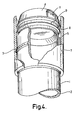
- Figures 3 and 4 are respectively perspective sectional views of the closure cap before and after application to a container and
- Figure 5 is a sectional view of an embodiment in which the two parts of the closure cap are formed as an integral unit and remain so until the closure cap is applied to a container. In this figure the closure cap is shown in position during application to a container and after it is in operative position.
- Figures 6 and 7 are detail views,and Figure 8 is a modification. Referring to the drawings, 1 is a container which has a smooth
inner surface 2 and an outer annular projecting ring 3. A two part closure cap comprises aninner member 4 in the form of a plug and anouter member 5 in the form of a sleeve, theinner member 4 being disposed co-axially within theouter member 5. Theouter member 5 has an internal annular recess 7 shaped to receive the annular projecting ring 3, the shape of the recess 7 and the ring 3 being such that it is relatively simple to push theouter member 5 downwardly over the ring 3 so that the ring 3 engages in the recess 7 but it is almost impossible to remove themember 5 again by a simple upward movement. - The
outer member 5 has an internal substantiallyannular bead 8 for engagement within anannular recess 9 in the outer surface of theinner member 4 and theouter member 5 also has an interruption 13 in thebead 8 forming a gap therein as indicated in Figure 7. Theinner member 4 has a thumb grip 11 and an embossed arrow or other mark on the top to indicate the position of the thumb grip 11. The interruption 13 in the substantiallyannular bead 8 is directly below or in the region of a gap or cut-out 10 in the peripheral top edge of theouter member 5 so that when upward pressure is applied to the thumb grip 11 of theinner member 4 through the gap or cut-out 10 theinner member 4 may be removed or pushed out of theouter member 5 in a tilting movement. It will be understood that pressure can be applied to the thumb grip 11 only when theinner member 4 is manipulated to bring the thumb grip 11 into registration with the gap or cut-out 10. - When upward pressure is applied to the thumb grip 11 to push the
inner member 4 out of theouter member 5 to open the container 1 theinner member 4 first tilts because upward pressure on the thumb grip raises the near side of theinner member 4 so that the top of theinner member 4 inclines downwardly away from the gap or cut-out 10. In the opening movement therefore theinner member 4 may be described as being flicked out of theouter member 5. - The assembly of the parts of the closure cap may be effected in such a way that the thumb grip 11 is out of registration with the gap or cut-out 10 in the periphery of the
outer member 5 so that if'the closure cap be applied automatically to a container, i.e by machine, the closure cap will be seated on the container in a child-resistant position. Then, in operation, to open the container a user moves theinner member 4 angularly relative to theouter member 5 until the thumb grip registers with the gap or cut-out 10 and then flicks out the inner member. To facilitate correct positioning of the inner member for opening the arrow or other indication referred to above may be provided on the top of the inner member, the inner member being pushed angularly around until the indicator points to the gap or cut-out 10. In this position a thumb of the user can be inserted through the gap or cut-out 10 and upward pressure then forces or flicks theinner member 4 out of theouter member 5. - The outer surface of the
inner member 4 is smooth except at the thumb grip 11 where it is stepped or otherwise shaped to enable a user to apply the required upward pressure to flick out the inner:member 4. When the closure cap is in operative position as shown e.g in Figure 2 aledge 14 at the lower end of theinner member 4 sits on theedge 15 around the mouth of the container 1 while an annular dependingportion 16 of theinner member 4 enters the mouth of the container 1 so that theinner member 4 of the closure cap turns on the edge of the mouth of the container 1 when theinner member 4 is manipulated relatively to theouter member 5. - Referring now to Figure 5 it will be noted that before application to the container 1 the closure cap is in the form of a one piece moulding comprising the
inner member 4 and theouter member 5 interconnected by afrangible connection 6. In full lines in Figure 5 the closure cap is shown in one piece before application to a container 1 and in dot and dash lines the closure cap is shown in its operative position. The closure cap as an integral unit is applied to a container 1 in a normal manner and top pressure is exerted on the closure cap to push theinner member 4 into theouter member 5, to break the frangible connection, to push theouter member 5 into a position to embrace the surface of tte container around its mouth and to seat theinner member 4 on or in the mouth. - If desired a tamper-resistant feature may be incorporated by providing a web or
webs 12, as shown in Figure 6 connecting the top of the inner member to the outer member. The web orwebs 12 must be broken before the inner member can be removed and breaking can readily be effected during rotation of the inner member to bring the thumb grip into registration with the gap or cut out. A broken web in the-closure cap of what should be an unopened container gives a clear visual indication that the contents of the container may have been tampered with. In a modification shown in Figure 8 theouter member 5 has a continuousannular bead 8 on its inner surface i.e. without the interruption 13 and the inner member has a substantiallyannular bead 20 below arecess 22 on its outer surface with aninterruption 21 therein as shown in Figure 8, below the thumb grip 11. When the closure cap is in operative position thebead 20 is bdow thebead 8 which is withinrecess 22 and the thumb grip 11 is out of registration with thegap 10. When the inner member is manipulated to bring the thumb grip 11 into registration with thegap 10 theinterruption 21 is below thegap 10 so that thebeads gap 10 and the inner member can be tilted and flicked out of the outer member. - In all cases the interruption should be of sufficient size to permit easy removal of the inner member e.g. 300 long. The
gap 10 may be the same size or of different size so long as it is big enough to receive the thumb of a user.
Claims (10)
Priority Applications (3)
| Application Number | Priority Date | Filing Date | Title |
|---|---|---|---|
| AT81300309T ATE14407T1 (en) | 1981-01-23 | 1981-01-23 | CLOSURES FOR CONTAINERS. |
| EP81300309A EP0056887B1 (en) | 1981-01-23 | 1981-01-23 | Container closure cap |
| DE8181300309T DE3171440D1 (en) | 1981-01-23 | 1981-01-23 | Container closure cap |
Applications Claiming Priority (1)
| Application Number | Priority Date | Filing Date | Title |
|---|---|---|---|
| EP81300309A EP0056887B1 (en) | 1981-01-23 | 1981-01-23 | Container closure cap |
Publications (2)
| Publication Number | Publication Date |
|---|---|
| EP0056887A1 true EP0056887A1 (en) | 1982-08-04 |
| EP0056887B1 EP0056887B1 (en) | 1985-07-24 |
Family
ID=8188197
Family Applications (1)
| Application Number | Title | Priority Date | Filing Date |
|---|---|---|---|
| EP81300309A Expired EP0056887B1 (en) | 1981-01-23 | 1981-01-23 | Container closure cap |
Country Status (3)
| Country | Link |
|---|---|
| EP (1) | EP0056887B1 (en) |
| AT (1) | ATE14407T1 (en) |
| DE (1) | DE3171440D1 (en) |
Cited By (3)
| Publication number | Priority date | Publication date | Assignee | Title |
|---|---|---|---|---|
| GB2164927A (en) * | 1984-10-02 | 1986-04-03 | Johnsen & Jorgensen | Closure for a container |
| EP0095005B1 (en) * | 1982-05-24 | 1986-07-16 | Philippe Claude Perinet | Containers with child-resistant closures |
| US5762215A (en) * | 1991-07-30 | 1998-06-09 | Glaxo Wellcome | Cap for a container |
Citations (4)
| Publication number | Priority date | Publication date | Assignee | Title |
|---|---|---|---|---|
| CH529676A (en) * | 1970-05-05 | 1972-10-31 | Thomae Gmbh Dr K | Container with secured stopper |
| DE2256423A1 (en) * | 1972-11-17 | 1974-05-22 | Geiger Plastic Kg | PACKAGING UNIT |
| US4065017A (en) * | 1975-10-22 | 1977-12-27 | Johnsen & Jorgensen (Plastics) Limited | Safety container and closure |
| GB1521352A (en) * | 1977-02-10 | 1978-08-16 | Johnsen Jorgensen Plastics Ltd | Containers and closures |
-
1981
- 1981-01-23 DE DE8181300309T patent/DE3171440D1/en not_active Expired
- 1981-01-23 EP EP81300309A patent/EP0056887B1/en not_active Expired
- 1981-01-23 AT AT81300309T patent/ATE14407T1/en not_active IP Right Cessation
Patent Citations (4)
| Publication number | Priority date | Publication date | Assignee | Title |
|---|---|---|---|---|
| CH529676A (en) * | 1970-05-05 | 1972-10-31 | Thomae Gmbh Dr K | Container with secured stopper |
| DE2256423A1 (en) * | 1972-11-17 | 1974-05-22 | Geiger Plastic Kg | PACKAGING UNIT |
| US4065017A (en) * | 1975-10-22 | 1977-12-27 | Johnsen & Jorgensen (Plastics) Limited | Safety container and closure |
| GB1521352A (en) * | 1977-02-10 | 1978-08-16 | Johnsen Jorgensen Plastics Ltd | Containers and closures |
Cited By (3)
| Publication number | Priority date | Publication date | Assignee | Title |
|---|---|---|---|---|
| EP0095005B1 (en) * | 1982-05-24 | 1986-07-16 | Philippe Claude Perinet | Containers with child-resistant closures |
| GB2164927A (en) * | 1984-10-02 | 1986-04-03 | Johnsen & Jorgensen | Closure for a container |
| US5762215A (en) * | 1991-07-30 | 1998-06-09 | Glaxo Wellcome | Cap for a container |
Also Published As
| Publication number | Publication date |
|---|---|
| DE3171440D1 (en) | 1985-08-29 |
| EP0056887B1 (en) | 1985-07-24 |
| ATE14407T1 (en) | 1985-08-15 |
Similar Documents
| Publication | Publication Date | Title |
|---|---|---|
| US4747498A (en) | Safety dispensing closure-container package | |
| US4111329A (en) | Container with tamperproof and stackable lid | |
| US3255928A (en) | Tamperproof closure for dispensing container | |
| EP1025014B1 (en) | Sports beverage snap closure | |
| US4726483A (en) | Tamper-evident closure employing inner cap and outer sleeve and container utilized therewith | |
| US3812994A (en) | Tamper-proof closure cap | |
| US4359166A (en) | Container closure cap | |
| EP0113550B1 (en) | A tamper-resistant and child-resistant closure | |
| JPS63138962A (en) | Vessel sealing device | |
| US4984716A (en) | Two piece tamper evident hinged closure cap | |
| EP0827913B1 (en) | A cap separable from bottle at the time of disposal | |
| US5398829A (en) | Tamper resistant, child resistant cap and spout assembly | |
| NZ208563A (en) | Tamper-evident closure cap | |
| CA2037728E (en) | Resealable bottle cap with push-pull closure | |
| US4458819A (en) | Seal for container safety plug | |
| US4353472A (en) | Closures for containers | |
| US4527702A (en) | Tamper evident container closure | |
| EP2114788B1 (en) | Tamper evident closure | |
| GB2255083A (en) | Closures | |
| US4449638A (en) | Tamper-resistant and child-resistant closure and container assembly | |
| EP0056887A1 (en) | Container closure cap | |
| US4065017A (en) | Safety container and closure | |
| JPH0253305B2 (en) | ||
| JP4034391B2 (en) | Plastic cap with separation function | |
| CA1160596A (en) | Closures for containers |
Legal Events
| Date | Code | Title | Description |
|---|---|---|---|
| PUAI | Public reference made under article 153(3) epc to a published international application that has entered the european phase |
Free format text: ORIGINAL CODE: 0009012 |
|
| AK | Designated contracting states |
Designated state(s): AT BE CH DE FR IT NL SE |
|
| 17P | Request for examination filed |
Effective date: 19830125 |
|
| GRAA | (expected) grant |
Free format text: ORIGINAL CODE: 0009210 |
|
| AK | Designated contracting states |
Designated state(s): AT BE CH DE FR IT LI NL SE |
|
| REF | Corresponds to: |
Ref document number: 14407 Country of ref document: AT Date of ref document: 19850815 Kind code of ref document: T |
|
| ITF | It: translation for a ep patent filed |
Owner name: UFFICIO BREVETTI RICCARDI & C. |
|
| REF | Corresponds to: |
Ref document number: 3171440 Country of ref document: DE Date of ref document: 19850829 |
|
| ET | Fr: translation filed | ||
| PLBE | No opposition filed within time limit |
Free format text: ORIGINAL CODE: 0009261 |
|
| STAA | Information on the status of an ep patent application or granted ep patent |
Free format text: STATUS: NO OPPOSITION FILED WITHIN TIME LIMIT |
|
| 26N | No opposition filed | ||
| PGFP | Annual fee paid to national office [announced via postgrant information from national office to epo] |
Ref country code: AT Payment date: 19870130 Year of fee payment: 7 |
|
| PGFP | Annual fee paid to national office [announced via postgrant information from national office to epo] |
Ref country code: NL Payment date: 19870131 Year of fee payment: 7 |
|
| PG25 | Lapsed in a contracting state [announced via postgrant information from national office to epo] |
Ref country code: AT Effective date: 19890123 |
|
| PG25 | Lapsed in a contracting state [announced via postgrant information from national office to epo] |
Ref country code: SE Effective date: 19890124 |
|
| PG25 | Lapsed in a contracting state [announced via postgrant information from national office to epo] |
Ref country code: LI Effective date: 19890131 Ref country code: CH Effective date: 19890131 Ref country code: BE Effective date: 19890131 |
|
| BERE | Be: lapsed |
Owner name: JOHNSEN & JORGENSEN (PLASTICS) LTD Effective date: 19890131 |
|
| PG25 | Lapsed in a contracting state [announced via postgrant information from national office to epo] |
Ref country code: NL Effective date: 19890801 |
|
| NLV4 | Nl: lapsed or anulled due to non-payment of the annual fee | ||
| PG25 | Lapsed in a contracting state [announced via postgrant information from national office to epo] |
Ref country code: FR Free format text: LAPSE BECAUSE OF NON-PAYMENT OF DUE FEES Effective date: 19890929 |
|
| REG | Reference to a national code |
Ref country code: CH Ref legal event code: PL |
|
| PG25 | Lapsed in a contracting state [announced via postgrant information from national office to epo] |
Ref country code: DE Effective date: 19891003 |
|
| REG | Reference to a national code |
Ref country code: FR Ref legal event code: ST |
|
| EUG | Se: european patent has lapsed |
Ref document number: 81300309.2 Effective date: 19891205 |