EP0056471A1 - Chargeur de batterie - Google Patents
Chargeur de batterie Download PDFInfo
- Publication number
- EP0056471A1 EP0056471A1 EP81110550A EP81110550A EP0056471A1 EP 0056471 A1 EP0056471 A1 EP 0056471A1 EP 81110550 A EP81110550 A EP 81110550A EP 81110550 A EP81110550 A EP 81110550A EP 0056471 A1 EP0056471 A1 EP 0056471A1
- Authority
- EP
- European Patent Office
- Prior art keywords
- voltage
- battery
- accordance
- battery charger
- switching means
- Prior art date
- Legal status (The legal status is an assumption and is not a legal conclusion. Google has not performed a legal analysis and makes no representation as to the accuracy of the status listed.)
- Withdrawn
Links
Images
Classifications
-
- H—ELECTRICITY
- H02—GENERATION; CONVERSION OR DISTRIBUTION OF ELECTRIC POWER
- H02J—CIRCUIT ARRANGEMENTS OR SYSTEMS FOR SUPPLYING OR DISTRIBUTING ELECTRIC POWER; SYSTEMS FOR STORING ELECTRIC ENERGY
- H02J7/00—Circuit arrangements for charging or depolarising batteries or for supplying loads from batteries
- H02J7/007—Regulation of charging or discharging current or voltage
- H02J7/00712—Regulation of charging or discharging current or voltage the cycle being controlled or terminated in response to electric parameters
- H02J7/007182—Regulation of charging or discharging current or voltage the cycle being controlled or terminated in response to electric parameters in response to battery voltage
- H02J7/007184—Regulation of charging or discharging current or voltage the cycle being controlled or terminated in response to electric parameters in response to battery voltage in response to battery voltage gradient
Definitions
- This invention pertains to a battery charger and specifically to a battery charger that automatically charges the batteries to which it is connected between a float voltage minimum and a float voltage maximum at a trickle charge rate and then at a faster rate and to a higher level when the voltages on such batteries fall below a predetermined low voltage below a float voltage minimum.
- Batteries in one common application provide emergency power to loads whenever the main power to a load is interrupted. This is particularly important in situations where the cessation of power cannot be tolerated, such as providing light to a hospital emergency room, power to computer systems to prevent the loss of data temporarily stored in non-permanent storage condition and the like.
- the invention embodiment disclosed provides high charge current through an SCR when the charger is activated or when the voltage on the battery being charged is sensed to be at a predetermined low level below float voltage minimum.
- a regulated dc derived from a battery under charge provides a reference voltage to a first comparator, the other input thereto being from the voltage level sensor connected to the battery.
- the comparator produces an output to set a latch or flip-flop, which, in turn, supplies a base voltage to a transistor emitter-follower, which gates on a second SCR, having one of its main terminals connected to ground.
- this second SCR is turned on, it draws off current from the gate of the first SCR and turns off the high charge current to the battery.
- a second reference-voltage-and-comparator produces an output when the voltage on the battery falls to float voltage minimum, to gate on a third SCR, this one having a series resistor connected thereto, to provide a trickle charge to the battery.
- This second comparator as it senses that the voltage on the battery has reached the float voltage maximum level shuts off or removes the gate from the third SCR and removes the trickle charge to the battery until the float voltage minimum level again occurs.
- a third reference-voltage-and-comparator produces an output that resets the latch, which turns off the emitter-follower and second SCR and gates on the first or high charge current SCR connected to the battery.
- More than one battery can be charged with the battery charger by providing sensing and isolating diodes before respective connections to the voltage sensor part of the circuit and to the charging SCR's, respectively.
- the isolating diodes prevent transients from circuit operation and from another battery from interferring with the charging operation of a given battery.
- the sensing diodes provide the battery with the lowest voltage to receive the most charge while not overcharging the other batteries, until all of the batteries connected to a common charger are substantially charged the same.
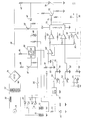
- the figure is a simplified schematic and block diagram of a preferred embodiment of the present invention.
- batteries 10 and 12 are shown connected to the battery charger for charging in accordance with the present invention.
- the high end of battery 10 is connected to the anode of sensing diode 14 and the high end of battery 12 is connected to the anode of diode 16.
- the cathodes of these diodes are connected to resistor 18, one of a series pair with resistor 20, which form a voltage divider. The junction between these points establishes a voltage sensing point for purposes hereafter explained.
- the negative end of the batteries and the opposite end of resistor 20 from the end connected to resistor 18 are connected to circuit common, which, for convenience, is illustrated as ground.
- the high side of battery 10 is connected to the cathode of isolation diode 22 and the high side of battery 12 is connected to the cathode of isolation diode 24.
- the anodes of these two diodes are connected to fuse 26 and then to the charging portion of the circuit, as explained below.
- the ac power distribution line is illustrated as ac source 28 and is connected via choke inductor 30 to a voltage dropping transformer 32, in conventional fashion.
- Choke inductor 30 limits the crest of the current applied from the ac power distribution line, typically at 120 volts, 60 Hz. Also, the current peak is smoothed over a half cycle and, therefore, power factor correction is also achieved.
- the output voltage from the secondary of transformer 32 is rectified in full-wave bridge rectifier 34 and the output current is available on line 36.
- a thyristor preferably in the form of SCR 38 is connected so that its main terminals connect line 36 with fuse 26 connected to the batteries through isolating diodes 22 and 24.
- the gate of SCR 38 is connected through diode 40 to a gate voltage provided by dropping resistor 42.
- SCR 38 is gated on for almost each half cycle of the rectified voltage to supply charging current via line 36 to the batteries.
- the charging current through this main SCR is typically 10 amperes.
- Battery 12 is also connected through resistor 44 to Zener diode 46 to provide a nominal 15-volt power supply.
- a 12-volt regulator 48 connected to this 15-volt output provides a regulated 12-volt output to each of three buffer amplifiers 50, 52 and 54.
- the outputs of these buffers are respectively connected to variable resistors 56, 58 and 60 to establish three different reference voltages respectively to comparators 62, 64 and 66.
- the other or compared inputs to these three comparators are each provided by buffer amplifier 68, the input of which is connected to the junction of resistors 18 and 20.
- the reference voltage is supplied to the "-" input for comparators 62 and 66 and is supplied to the * +" input for comparator 64 for purposes to be described below.
- Capacitor 70 in parallel with resistor 20 reduces ripple by providing some filtering.
- the output of comparator 62 is connected to latch or flip-flop circuit 72.
- the output of latch 72 is connected through base resistor 74 to emitter-follower 76, the emitter of which is connected to the gate of a thyristor in the form of SCR 78.
- the main terminals of SC R 78 are connected respectively to the junction between diode 40 and resistor 42 and common or ground.
- the output of comparator 66 is connected to an element 80 for isolating the low voltage part of the circuit from SCR 82.
- isolation element 80 is an optoisolated triac, Motorola MOC3011. This element is connected through resistor 84 to line 36 and to voltage clamping Zener diode 86 for proper operation. Operation with respect to SCR 82 is such that when the input from comparator is removed, SCR 82 receives a proper gate for turning on the SCR. Conversely, when there is an output from comparator 66, the gate is removed from SCR 82 to turn the SCR off.
- SCR 82 has one of its main terminals connected in series with resistor 88 and its other main terminal to provide charging current to the batteries.
- Resistor 88 assures that the current through SCR 82 when it is conducting is very much less than the current through SCR 38 when it is conducting.
- the trickle charge current is typically about 200 milliamperes when the high charge current is about 10 amperes.
- diodes 22 and 24 effectively prevent transients from the circuit or from the other battery or batteries from affecting the charge on the batteries connected thereto. Further, since the batteries are connected to a common point to the charging network just described, the charge provided tends to be supplied to the battery most in need.
- a typical operation establishes the four voltage operation points per battery cell, as follows: float voltage minimum at 2.2 volts; float voltage maximum at 2.3 volts; predetermined low voltage below float voltage minimum at 2.0 volts; and predetermined high voltage above float voltage maximum at 2.7 volts.
- latch 72 When trickle charge only is being applied to the batteries, latch 72 is set and there is an output on line 94 that can be connected to the appropriate lamp or other indicator. On the other hand, when full or high charge current is being supplied to the batteries, the latch is unset and therefore there is an output on line 96 that can be connected to a lamp or other indicator, if desired.
Applications Claiming Priority (2)
| Application Number | Priority Date | Filing Date | Title |
|---|---|---|---|
| US22537481A | 1981-01-15 | 1981-01-15 | |
| US225374 | 1981-01-15 |
Publications (1)
| Publication Number | Publication Date |
|---|---|
| EP0056471A1 true EP0056471A1 (fr) | 1982-07-28 |
Family
ID=22844611
Family Applications (1)
| Application Number | Title | Priority Date | Filing Date |
|---|---|---|---|
| EP81110550A Withdrawn EP0056471A1 (fr) | 1981-01-15 | 1981-12-17 | Chargeur de batterie |
Country Status (5)
| Country | Link |
|---|---|
| EP (1) | EP0056471A1 (fr) |
| AU (1) | AU7613481A (fr) |
| CA (1) | CA1161497A (fr) |
| ES (1) | ES8302375A1 (fr) |
| GB (1) | GB2091502A (fr) |
Cited By (2)
| Publication number | Priority date | Publication date | Assignee | Title |
|---|---|---|---|---|
| GB2183944A (en) * | 1985-12-09 | 1987-06-10 | Levitt Safety Ltd | Battery charger |
| US4692682A (en) * | 1985-12-23 | 1987-09-08 | Levitt Safety Limited | Nicad battery charger |
Families Citing this family (52)
| Publication number | Priority date | Publication date | Assignee | Title |
|---|---|---|---|---|
| GB2155257A (en) * | 1983-09-13 | 1985-09-18 | Astratec Electronics Limited | Battery charger |
| US4715523A (en) * | 1984-11-12 | 1987-12-29 | Lebedev Vladimir K | Electromagnetic power drive for a friction welding machine |
| US4686424A (en) * | 1986-01-21 | 1987-08-11 | Harvey Hubbell Incorporated | Emergency lighting circuits |
| GB2247366B (en) * | 1990-08-21 | 1994-07-20 | Peter Murray | A two state constant current battery charging system |
| KR930011132B1 (ko) * | 1991-11-01 | 1993-11-24 | 삼성전자 주식회사 | 배터리의 쾌속충전 제어회로 |
| FI924426A (fi) * | 1992-10-01 | 1994-04-02 | Fps Power Systems Oy Ab | Foerfarande foer att kontrollera och uppraetthaolla laddningen hos ett ackumulatorbatteri i en reservstroemkaella och en reservstroemkaella |
| DE19545655A1 (de) * | 1995-12-07 | 1997-06-12 | Cenith Control Gmbh | Kaskadierbarer Laderegler |
| USD707263S1 (en) | 2011-10-07 | 2014-06-17 | Caterpillar, Inc. | Tip for a ground engaging machine implement |
| USD706307S1 (en) | 2011-10-07 | 2014-06-03 | Caterpillar, Inc. | Adapter for a ground engaging machine implement |
| USD706840S1 (en) | 2011-10-07 | 2014-06-10 | Caterpillar, Inc. | Tip for a ground engaging machine implement |
| USD707264S1 (en) | 2011-10-07 | 2014-06-17 | Caterpillar Inc. | Adapter for a ground engaging machine implement |
| USD727980S1 (en) | 2014-04-08 | 2015-04-28 | Caterpillar Inc. | Tip for a ground engaging machine implement |
| USD706839S1 (en) | 2011-10-07 | 2014-06-10 | Caterpillar, Inc. | Tip for a ground engaging machine implement |
| USD706312S1 (en) | 2011-10-07 | 2014-06-03 | Caterpiller, Inc. | Tip for a ground engaging machine implement |
| USD728636S1 (en) | 2013-08-01 | 2015-05-05 | Caterpillar Inc. | Coupler and tip for a ground engaging machine implement |
| USD728637S1 (en) | 2013-08-01 | 2015-05-05 | Caterpillar Inc. | Tip for a ground engaging machine implement |
| USD728635S1 (en) | 2013-08-01 | 2015-05-05 | Caterpillar Inc. | Coupler for a ground engaging machine implement |
| USD774567S1 (en) | 2015-08-12 | 2016-12-20 | Caterpillar Inc. | Tip for a ground engaging machine implement |
| USD774565S1 (en) | 2015-08-12 | 2016-12-20 | Caterpillar Inc. | Tip for a ground engaging machine implement |
| USD775243S1 (en) | 2015-08-12 | 2016-12-27 | Caterpillar Inc. | Tip for a ground engaging machine implement |
| USD775673S1 (en) | 2015-08-12 | 2017-01-03 | Caterpillar Inc. | Tip for a ground engaging machine implement |
| USD775242S1 (en) | 2015-08-12 | 2016-12-27 | Caterpillar Inc. | Tip for a ground engaging machine implement |
| USD774110S1 (en) | 2015-08-12 | 2016-12-13 | Caterpillar Inc. | Tip for a ground engaging machine implement |
| USD774108S1 (en) | 2015-08-12 | 2016-12-13 | Caterpillar Inc. | Tip for a ground engaging machine implement |
| USD775241S1 (en) | 2015-08-12 | 2016-12-27 | Caterpillar Inc. | Tip for a ground engaging machine implement |
| USD774566S1 (en) | 2015-08-12 | 2016-12-20 | Caterpillar Inc. | Tip for a ground engaging machine implement |
| USD775240S1 (en) | 2015-08-12 | 2016-12-27 | Caterpillar Inc. | Tip for a ground engaging machine implement |
| USD774109S1 (en) | 2015-08-12 | 2016-12-13 | Caterpillar Inc. | Tip for a ground engaging machine implement |
| USD774564S1 (en) | 2015-08-12 | 2016-12-20 | Caterpillar Inc. | Tip for a ground engaging machine implement |
| CN107994622A (zh) * | 2016-10-26 | 2018-05-04 | 宁德时代新能源科技股份有限公司 | 电池供电电路 |
| USD805562S1 (en) | 2016-12-15 | 2017-12-19 | Caterpillar Inc. | Adapter for a ground engaging machine implement |
| USD803902S1 (en) | 2016-12-15 | 2017-11-28 | Caterpillar Inc. | Tip for a ground engaging machine implement |
| USD806758S1 (en) | 2016-12-15 | 2018-01-02 | Caterpillar Inc. | Tip for a ground engaging machine implement |
| USD806759S1 (en) | 2016-12-15 | 2018-01-02 | Caterpillar Inc. | Tip for a ground engaging machine implement |
| USD803898S1 (en) | 2016-12-15 | 2017-11-28 | Caterpillar Inc. | Tip for a ground engaging machine implement |
| USD806140S1 (en) | 2016-12-15 | 2017-12-26 | Caterpillar Inc. | Adapter for a ground engaging machine implement |
| USD803274S1 (en) | 2016-12-15 | 2017-11-21 | Caterpillar Inc. | Tip for a ground engaging machine implement |
| USD803899S1 (en) | 2016-12-15 | 2017-11-28 | Caterpillar Inc. | Tip for a ground engaging machine implement |
| USD806141S1 (en) | 2016-12-15 | 2017-12-26 | Caterpillar Inc. | Adapter for a ground engaging machine implement |
| USD806139S1 (en) | 2016-12-15 | 2017-12-26 | Caterpillar Inc. | Adapter for a ground engaging machine implement |
| USD805112S1 (en) | 2016-12-15 | 2017-12-12 | Caterpillar Inc. | Tip for a ground engaging machine implement |
| USD803897S1 (en) | 2016-12-15 | 2017-11-28 | Caterpillar Inc. | Tip for a ground engaging machine implement |
| USD803275S1 (en) | 2016-12-15 | 2017-11-21 | Caterpillar Inc. | Tip for a ground engaging machine implement |
| USD803900S1 (en) | 2016-12-15 | 2017-11-28 | Caterpillar Inc. | Tip for a ground engaging machine implement |
| USD803901S1 (en) | 2016-12-15 | 2017-11-28 | Caterpillar Inc. | Tip for a ground engaging machine implement |
| USD806142S1 (en) | 2016-12-15 | 2017-12-26 | Caterpillar Inc. | Adapter for a ground engaging machine implement |
| USD832310S1 (en) | 2017-08-30 | 2018-10-30 | Caterpillar Inc. | Adapter for a ground engaging machine implement |
| USD888785S1 (en) | 2019-03-07 | 2020-06-30 | Caterpillar Inc. | Adapter for a ground engaging machine implement |
| USD905765S1 (en) | 2019-03-07 | 2020-12-22 | Caterpillar Inc. | Adapter for a ground engaging machine implement |
| USD945498S1 (en) | 2020-11-18 | 2022-03-08 | Caterpillar Inc. | Adapter for a ground engaging machine implement |
| USD945499S1 (en) | 2020-11-18 | 2022-03-08 | Caterpillar Inc. | Adapter for a ground engaging machine implement |
| CN113517736B (zh) * | 2021-05-31 | 2023-04-07 | 上海航天电源技术有限责任公司 | 一种电池组维护方法 |
Citations (6)
| Publication number | Priority date | Publication date | Assignee | Title |
|---|---|---|---|---|
| US3576487A (en) * | 1969-12-22 | 1971-04-27 | Gen Electric | Battery charging circuit utilizing multivibrator locking means |
| US3795818A (en) * | 1973-02-09 | 1974-03-05 | Shetec Inc | Emergency power supply |
| US3919618A (en) * | 1974-06-10 | 1975-11-11 | Gates Rubber Co | Hysteresis battery charger |
| DE2604198A1 (de) * | 1976-02-04 | 1977-08-11 | Braun Ag | Schaltungsanordnung zum schnellen laden eines akkumulators |
| FR2400273A1 (fr) * | 1977-08-08 | 1979-03-09 | Conseils Services Internationa | Circuit de charge et de decharge de batteries en parallele sur un utilisateur |
| GB2036471A (en) * | 1978-11-22 | 1980-06-25 | Gen Motors Corp | Secondary cell charging systems |
-
1981
- 1981-10-08 CA CA000387538A patent/CA1161497A/fr not_active Expired
- 1981-10-08 AU AU76134/81A patent/AU7613481A/en not_active Abandoned
- 1981-11-20 ES ES507331A patent/ES8302375A1/es not_active Expired
- 1981-12-09 GB GB8137186A patent/GB2091502A/en not_active Withdrawn
- 1981-12-17 EP EP81110550A patent/EP0056471A1/fr not_active Withdrawn
Patent Citations (7)
| Publication number | Priority date | Publication date | Assignee | Title |
|---|---|---|---|---|
| US3576487A (en) * | 1969-12-22 | 1971-04-27 | Gen Electric | Battery charging circuit utilizing multivibrator locking means |
| US3795818A (en) * | 1973-02-09 | 1974-03-05 | Shetec Inc | Emergency power supply |
| US3919618A (en) * | 1974-06-10 | 1975-11-11 | Gates Rubber Co | Hysteresis battery charger |
| DE2604198A1 (de) * | 1976-02-04 | 1977-08-11 | Braun Ag | Schaltungsanordnung zum schnellen laden eines akkumulators |
| US4081739A (en) * | 1976-02-04 | 1978-03-28 | Braun Aktiengesellschaft | Circuit for quick charging of batteries |
| FR2400273A1 (fr) * | 1977-08-08 | 1979-03-09 | Conseils Services Internationa | Circuit de charge et de decharge de batteries en parallele sur un utilisateur |
| GB2036471A (en) * | 1978-11-22 | 1980-06-25 | Gen Motors Corp | Secondary cell charging systems |
Cited By (2)
| Publication number | Priority date | Publication date | Assignee | Title |
|---|---|---|---|---|
| GB2183944A (en) * | 1985-12-09 | 1987-06-10 | Levitt Safety Ltd | Battery charger |
| US4692682A (en) * | 1985-12-23 | 1987-09-08 | Levitt Safety Limited | Nicad battery charger |
Also Published As
| Publication number | Publication date |
|---|---|
| CA1161497A (fr) | 1984-01-31 |
| GB2091502A (en) | 1982-07-28 |
| ES507331A0 (es) | 1983-01-01 |
| ES8302375A1 (es) | 1983-01-01 |
| AU7613481A (en) | 1982-07-22 |
Similar Documents
| Publication | Publication Date | Title |
|---|---|---|
| EP0056471A1 (fr) | Chargeur de batterie | |
| US4467265A (en) | Battery charger | |
| US5237259A (en) | Charging method for secondary battery | |
| US3735233A (en) | Battery charger apparatus having multiple modes of operation and automatic switching therebetween | |
| US5130634A (en) | Battery charger for a portable wireless telephone set having means for tricklingly charging the battery with an increased current during a stand-by period of the telephone set | |
| US3454859A (en) | Nickel-cadmium battery reconditioner | |
| CA1041595A (fr) | Systeme d'eclairage de secours | |
| US4354118A (en) | Battery backup supply control means and method | |
| CN1038460C (zh) | 一种电压稳压器 | |
| EP0580351A2 (fr) | Appareil de charge de batterie | |
| US5432427A (en) | Battery charging control system | |
| EP0103124A2 (fr) | Circuit chargeur de batterie de lampe de poche | |
| US6420853B1 (en) | Battery charger capable of accurately determining fully charged condition regardless of batteries with different charge chracteristics | |
| US4342954A (en) | Battery conditioning methods and apparatus | |
| CA1223304A (fr) | Chargeur de batterie a commutation haute frequence | |
| KR19990037303A (ko) | 셀용 충전 전류 어댑터 회로 또는 배터리들 | |
| CA2174845C (fr) | Controleur de polarisation d'element d'accumulateur | |
| SU907698A1 (ru) | Устройство бесперебойного электропитани | |
| KR920009362B1 (ko) | 정전류에 의한 충전장치 | |
| US5449998A (en) | Charger for dry galvanic cells using asymmetrical current | |
| JPS6227004Y2 (fr) | ||
| JP3107605B2 (ja) | 電池充電装置 | |
| KR950009298B1 (ko) | 밧데리의 충전모드 절환회로 | |
| JP2622851B2 (ja) | 2次電池の充電装置 | |
| JPS58148633A (ja) | 自動充電装置 |
Legal Events
| Date | Code | Title | Description |
|---|---|---|---|
| PUAI | Public reference made under article 153(3) epc to a published international application that has entered the european phase |
Free format text: ORIGINAL CODE: 0009012 |
|
| AK | Designated contracting states |
Designated state(s): BE FR IT |
|
| 17P | Request for examination filed |
Effective date: 19830125 |
|
| STAA | Information on the status of an ep patent application or granted ep patent |
Free format text: STATUS: THE APPLICATION IS DEEMED TO BE WITHDRAWN |
|
| 18D | Application deemed to be withdrawn |
Effective date: 19840703 |
|
| RIN1 | Information on inventor provided before grant (corrected) |
Inventor name: HIERHOLZER, ALTON G., JR. |