EP0056295A1 - Valved closure for kegs or casks - Google Patents
Valved closure for kegs or casks Download PDFInfo
- Publication number
- EP0056295A1 EP0056295A1 EP82300004A EP82300004A EP0056295A1 EP 0056295 A1 EP0056295 A1 EP 0056295A1 EP 82300004 A EP82300004 A EP 82300004A EP 82300004 A EP82300004 A EP 82300004A EP 0056295 A1 EP0056295 A1 EP 0056295A1
- Authority
- EP
- European Patent Office
- Prior art keywords
- valve body
- lugs
- neck
- collar
- valved closure
- Prior art date
- Legal status (The legal status is an assumption and is not a legal conclusion. Google has not performed a legal analysis and makes no representation as to the accuracy of the status listed.)
- Granted
Links
Images


Classifications
-
- B—PERFORMING OPERATIONS; TRANSPORTING
- B67—OPENING, CLOSING OR CLEANING BOTTLES, JARS OR SIMILAR CONTAINERS; LIQUID HANDLING
- B67D—DISPENSING, DELIVERING OR TRANSFERRING LIQUIDS, NOT OTHERWISE PROVIDED FOR
- B67D1/00—Apparatus or devices for dispensing beverages on draught
- B67D1/08—Details
- B67D1/0829—Keg connection means
- B67D1/0831—Keg connection means combined with valves
- B67D1/0832—Keg connection means combined with valves with two valves disposed concentrically
Definitions
- This invention relates to valved closures for pressure vessels, such as kegs or casks for beverages dispensed through the valved closure by pressure gas admitted to the keg or cask through the closure.
- the object of the invention is to provide such a valved closure the unauthorised removal of which, or its components, is rendered difficult by making the manner of removal unobvious and also reducing to a minimum the risk of ejection of the valve of the closure by the pressure gas.
- a valved closure for a pressure vessel such as a keg or a cask, comprises an externally screw-threaded neck, for rigid attachment as a mounting ring to the rim of a tap-hole in the vessel, the neck having internal angularly-spaced radial lugs, a valve-containing tubular body inserted coaxially in the neck, the valve body having external angularly-spaced radial lugs engageable with and disengageable from the neck lugs by axial displacement and rotation of the valve body, an internally screw-threaded collar carried by the valve body and screwed on to the neck, check means preventing axial withdrawal of the valve body from the collar and a locking ring removably interposed axially between opposed parts of the collar and neck to hold the collar in a position preventing axial displacement of the valve body for disengagement of the lugs.
- a resilient seal is provided between the valve body and the neck and the seal must be compressed by axial movement of the body before the lugs can be brought into engagement by rotation of the body.
- the locking ring is a split ring which can be opened at its split and passed laterally into or from its locking position and it may also be frangible so that its removal involves breakage, thus providing evidence of tampering and preventing re-use.
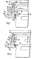
- valve closure comprises a valve body 10 housing valve components, generally indicated by the reference 20 in Fig. 4, of the kind which are assembled in the body 10 from its inner end, the body including internally a valve seat 21 against which the valve seals and which prevents ejection of the valve.
- the valve itself does not form part of the present invention and need not be further described.
- the body 10 has a top flange 10a, of lobed shape to provide a hand-grip for turning, a rebate forming an inward axially-facing shoulder lOb, angularly-spaced circumferentially-extending lugs 11 at about mid-length of the body, these lugs having at their ends anti-rotation stops lla, and an inward shoulder 10c near the inner end of the main part of the body.
- the body 10 is inserted coaxially into a neck 12 which has a flange 12a at its inner end to form a mounting ring which is welded to the rim of a tap-hole of a keg or cask (not shown).
- a resilient 0-ring seal 13 lies between a shoulder 12b on the neck and the shoulder 10c on the body 10.
- the neck 12 has an external screw-thread 14 and internally has angularly-spaced lugs 15 of a circumferential dimension to allow the lugs 11 to pass axially between them and to fit between the anti-rotation stops lla when the body is turned to inter-engage the lugs.
- the valve closure also includes a collar 16 which has an internal screw-thread 16a to engage the thread 14 on the neck. Within its outer end the collar has a circumferential groove in which is engaged a split metal check ring 17 the internal diameter of which is less than the outer diameter of the lugs 11.
- neck 12 will remain fixed to the cask or keg and only the remaining components will be removed at any time.
- the body and collar 16 are first axially inter-engaged and loosely held together by inserting the check ring 17 into its groove whilst projecting into the axial gap between the shoulder 10b and the lugs 11.
- valve body 10 is now pushed down to compress the seal 13 to carry the lugs 11 axially clear of lugs 15 and the body is then rotated to align the sets of lugs 11 and 15. On releasing the body, the lugs 11 rise into abutment with lugs 15 which lie between the anti-rotation stops lla as shown in Fig. 2.
- the collar 16 is now unscrewed upwardly on the thread 14 until its upper end abuts the valve body flange 10a and the check ring 17 abuts the shoulder lOb (Fig. 3).
- a split locking ring 19 of plastics or other frangible material is now passed laterally into the groove 12c to occupy the axial space between the lower end of the collar 16 and the bottom of the groove.
- the components are so dimensioned that unless the lugs 15 are properly engaged between the stops lla the locking ring 19 cannot be inserted between the collar 16 and the bottom of groove 12c.
- Removal of the valve body 10 is effected by a reverse operation. After ensuring that the pressure within the cask or keg is fully relieved, the locking ring 19 is removed, the collar 16 is screwed down to contact the bottom of groove 12c, and the lugs 11, 15 are disengaged by depressing and then turning the valve body 10. The body 10 and collar 16 may now be removed.
- valve body 10 cannot be rotated because the anti-rotation stops 11a contact the fixed lugs 15. Also the collar 16 shrouds the neck 12 and cannot be screwed up or down so that the method of removal of the body and collar is not obvious, thus militating against tampering with the closure.
- the shoulders 10c and 12b are bevelled to facilitate rolling displacement of the 0-ring seal 13 during assembly of the closure.
- the locking ring 19 as shown in Figs. 4 and 5 is weakened by a deep circumferential groove 19a in its underside so that when the ring is removed, such as by a hook engaged in an eye 19b at the split of the ring, the outer part of the ring will tear before the remainder of the ring leaves the groove 12c. Thus the ring 19 is not re-usable and its torn state indicates tampering.
Abstract
Description
- This invention relates to valved closures for pressure vessels, such as kegs or casks for beverages dispensed through the valved closure by pressure gas admitted to the keg or cask through the closure.
- The object of the invention is to provide such a valved closure the unauthorised removal of which, or its components, is rendered difficult by making the manner of removal unobvious and also reducing to a minimum the risk of ejection of the valve of the closure by the pressure gas.
- According to the invention, a valved closure, for a pressure vessel such as a keg or a cask, comprises an externally screw-threaded neck, for rigid attachment as a mounting ring to the rim of a tap-hole in the vessel, the neck having internal angularly-spaced radial lugs, a valve-containing tubular body inserted coaxially in the neck, the valve body having external angularly-spaced radial lugs engageable with and disengageable from the neck lugs by axial displacement and rotation of the valve body, an internally screw-threaded collar carried by the valve body and screwed on to the neck, check means preventing axial withdrawal of the valve body from the collar and a locking ring removably interposed axially between opposed parts of the collar and neck to hold the collar in a position preventing axial displacement of the valve body for disengagement of the lugs.
- Preferably, a resilient seal is provided between the valve body and the neck and the seal must be compressed by axial movement of the body before the lugs can be brought into engagement by rotation of the body.
- Conveniently the locking ring is a split ring which can be opened at its split and passed laterally into or from its locking position and it may also be frangible so that its removal involves breakage, thus providing evidence of tampering and preventing re-use.
- The above and other features of the invention will now be described with reference, by way of example, to the accompanying drawings, in which:-
- Figs. 1, 2 and 3 are part axial sections showing a closure according to the invention in successive stages of assembly and locking,
- Fig. 4 is an exploded part-sectional view of the components of a closure essentially similar to that of Figs. 1 to 3 but with some modification in design.
- Fig. 5, on a smaller scale, is an inverted plan of the locking ring of Fig. 4, and
- Fig. 6, on a smaller scale, is a side elevation of a modified design of valve body.
- The valve closure comprises a
valve body 10 housing valve components, generally indicated by thereference 20 in Fig. 4, of the kind which are assembled in thebody 10 from its inner end, the body including internally avalve seat 21 against which the valve seals and which prevents ejection of the valve. The valve itself does not form part of the present invention and need not be further described. - The
body 10 has atop flange 10a, of lobed shape to provide a hand-grip for turning, a rebate forming an inward axially-facing shoulder lOb, angularly-spaced circumferentially-extendinglugs 11 at about mid-length of the body, these lugs having at their ends anti-rotation stops lla, and aninward shoulder 10c near the inner end of the main part of the body. - The
body 10 is inserted coaxially into aneck 12 which has aflange 12a at its inner end to form a mounting ring which is welded to the rim of a tap-hole of a keg or cask (not shown). - A resilient 0-
ring seal 13 lies between ashoulder 12b on the neck and theshoulder 10c on thebody 10. - The
neck 12 has an external screw-thread 14 and internally has angularly-spacedlugs 15 of a circumferential dimension to allow thelugs 11 to pass axially between them and to fit between the anti-rotation stops lla when the body is turned to inter-engage the lugs. - The valve closure also includes a
collar 16 which has an internal screw-thread 16a to engage thethread 14 on the neck. Within its outer end the collar has a circumferential groove in which is engaged a splitmetal check ring 17 the internal diameter of which is less than the outer diameter of thelugs 11. - In practice the
neck 12 will remain fixed to the cask or keg and only the remaining components will be removed at any time. - To assemble the
body 10 and collar 16 to theneck 12, the body and collar are first axially inter-engaged and loosely held together by inserting thecheck ring 17 into its groove whilst projecting into the axial gap between theshoulder 10b and thelugs 11. - This assembly is now offered up to the neck with the body entering the neck and the collar outside the neck, the
seal 13 being on thebody 10 againstshoulder 10c. When thethreads seal 13 will be belowlugs 15 at the level of space 18 (Fig. 1). - With the
lugs 11 angularly offset from thelugs 15, thecollar 16 is now screwed-down until its lower end abuts the bottom of anannular groove 12c in theflange 12a, the components then being in the positions shown in Fig. 1. It will be noted that thelugs 11 axiallyoverlap lugs 15. - The
valve body 10 is now pushed down to compress theseal 13 to carry thelugs 11 axially clear oflugs 15 and the body is then rotated to align the sets oflugs lugs 11 rise into abutment withlugs 15 which lie between the anti-rotation stops lla as shown in Fig. 2. - The
collar 16 is now unscrewed upwardly on thethread 14 until its upper end abuts thevalve body flange 10a and thecheck ring 17 abuts the shoulder lOb (Fig. 3). Asplit locking ring 19 of plastics or other frangible material is now passed laterally into thegroove 12c to occupy the axial space between the lower end of thecollar 16 and the bottom of the groove. - It will be clear that the
body 10 can neither be rotated, this being prevented by theengaging lugs collar 16 abutting both theflange 10a and thelocking ring 19. - Further, the components are so dimensioned that unless the
lugs 15 are properly engaged between the stops lla thelocking ring 19 cannot be inserted between thecollar 16 and the bottom ofgroove 12c. - Removal of the
valve body 10 is effected by a reverse operation. After ensuring that the pressure within the cask or keg is fully relieved, thelocking ring 19 is removed, thecollar 16 is screwed down to contact the bottom ofgroove 12c, and thelugs valve body 10. Thebody 10 andcollar 16 may now be removed. - If the operator fails to de-pressurise the cask or keg before attempting removal, release of pressure will occur automatically when the
lugs body 10 will be forced upwards, it will be prevented from ejection by thelugs 11 abutting thecheck ring 17. Also theseal 13 will travel upwards so that pressure gas escapes around the seal through thespace 18. - It will be clear that when the closure is assembled the
valve body 10 cannot be rotated because the anti-rotation stops 11a contact the fixedlugs 15. Also thecollar 16 shrouds theneck 12 and cannot be screwed up or down so that the method of removal of the body and collar is not obvious, thus militating against tampering with the closure. - Modified design details are shown in Figs. 4, 5 and 6.
- The
shoulders ring seal 13 during assembly of the closure. - As shown in Fig. 6, increased height is given to one end stop lla on each
lug 11 which encounters therespective lug 15 when thebody 10 is turned in assembly of the closure. These higher stops preclude thebody 10 being rotated beyond alignment of thelugs body 10 is thrust in too far before rotation. - The
locking ring 19 as shown in Figs. 4 and 5 is weakened by a deepcircumferential groove 19a in its underside so that when the ring is removed, such as by a hook engaged in aneye 19b at the split of the ring, the outer part of the ring will tear before the remainder of the ring leaves thegroove 12c. Thus thering 19 is not re-usable and its torn state indicates tampering.
Claims (6)
Priority Applications (1)
| Application Number | Priority Date | Filing Date | Title |
|---|---|---|---|
| AT82300004T ATE10083T1 (en) | 1981-01-05 | 1982-01-04 | VALVE CLOSURE FOR DRUMS OR BARRELS. |
Applications Claiming Priority (2)
| Application Number | Priority Date | Filing Date | Title |
|---|---|---|---|
| GB8100179 | 1981-01-05 | ||
| GB8100179 | 1981-01-05 |
Publications (2)
| Publication Number | Publication Date |
|---|---|
| EP0056295A1 true EP0056295A1 (en) | 1982-07-21 |
| EP0056295B1 EP0056295B1 (en) | 1984-10-31 |
Family
ID=10518797
Family Applications (1)
| Application Number | Title | Priority Date | Filing Date |
|---|---|---|---|
| EP82300004A Expired EP0056295B1 (en) | 1981-01-05 | 1982-01-04 | Valved closure for kegs or casks |
Country Status (4)
| Country | Link |
|---|---|
| EP (1) | EP0056295B1 (en) |
| AT (1) | ATE10083T1 (en) |
| DE (1) | DE3261079D1 (en) |
| ES (1) | ES262435Y (en) |
Cited By (9)
| Publication number | Priority date | Publication date | Assignee | Title |
|---|---|---|---|---|
| GB2158906A (en) * | 1984-05-18 | 1985-11-20 | Micro Matic As | Valve closure for kegs |
| GB2192621A (en) * | 1986-06-18 | 1988-01-20 | Micro Matic As | Valve coupling |
| WO1991002694A1 (en) * | 1989-08-24 | 1991-03-07 | Micro Matic A/S | A valve arrangement |
| WO1995016613A2 (en) * | 1993-12-09 | 1995-06-22 | Micro Matic A/S | Blocking arrangement |
| RU2489346C2 (en) * | 2011-08-09 | 2013-08-10 | Николай Владимирович Ушаков | Valve device for fluid storage and discharge |
| NL2012726A (en) * | 2012-10-30 | 2014-05-19 | Heineken Supply Chain Bv | Container and valve for a container. |
| WO2014070004A3 (en) * | 2012-10-30 | 2014-09-04 | Heineken Supply Chain B.V. | Beverage container and valve for a beverage container |
| EP3348517A4 (en) * | 2016-09-22 | 2019-05-22 | Obschestvo s orgranichennoy otvetstvennostiu "Kazansky zavod "EUROPLAST" | Valve structure for a pet keg |
| GB2584967A (en) * | 2018-06-25 | 2020-12-23 | Packaging Innovation Ltd | System and method for distributing and dispensing liquids |
Families Citing this family (1)
| Publication number | Priority date | Publication date | Assignee | Title |
|---|---|---|---|---|
| RU172364U1 (en) * | 2016-10-27 | 2017-07-05 | Артем Андреевич Костин | COVER FOR CAPACITY WITH LIQUID UNDER PRESSURE |
Citations (1)
| Publication number | Priority date | Publication date | Assignee | Title |
|---|---|---|---|---|
| US3497114A (en) * | 1968-11-05 | 1970-02-24 | Mack S Johnston | Beer tapping device |
-
1982
- 1982-01-04 DE DE8282300004T patent/DE3261079D1/en not_active Expired
- 1982-01-04 AT AT82300004T patent/ATE10083T1/en not_active IP Right Cessation
- 1982-01-04 EP EP82300004A patent/EP0056295B1/en not_active Expired
- 1982-01-05 ES ES1982262435U patent/ES262435Y/en not_active Expired
Patent Citations (1)
| Publication number | Priority date | Publication date | Assignee | Title |
|---|---|---|---|---|
| US3497114A (en) * | 1968-11-05 | 1970-02-24 | Mack S Johnston | Beer tapping device |
Cited By (19)
| Publication number | Priority date | Publication date | Assignee | Title |
|---|---|---|---|---|
| GB2158906A (en) * | 1984-05-18 | 1985-11-20 | Micro Matic As | Valve closure for kegs |
| GB2192621A (en) * | 1986-06-18 | 1988-01-20 | Micro Matic As | Valve coupling |
| GB2192621B (en) * | 1986-06-18 | 1990-06-13 | Micro Matic As | A valve coupling for securing a valve in a pressure container |
| WO1991002694A1 (en) * | 1989-08-24 | 1991-03-07 | Micro Matic A/S | A valve arrangement |
| US5242092A (en) * | 1989-08-24 | 1993-09-07 | Micro Matic A/S | Valve arrangement for transportable container for storing and distributing liquid under pressure |
| WO1995016613A2 (en) * | 1993-12-09 | 1995-06-22 | Micro Matic A/S | Blocking arrangement |
| WO1995016613A3 (en) * | 1993-12-09 | 1995-12-07 | Micro Matic As | Blocking arrangement |
| US6047994A (en) * | 1993-12-09 | 2000-04-11 | Micro Matic A/S | Blocking arrangement |
| RU2489346C2 (en) * | 2011-08-09 | 2013-08-10 | Николай Владимирович Ушаков | Valve device for fluid storage and discharge |
| NL2012726A (en) * | 2012-10-30 | 2014-05-19 | Heineken Supply Chain Bv | Container and valve for a container. |
| WO2014070004A3 (en) * | 2012-10-30 | 2014-09-04 | Heineken Supply Chain B.V. | Beverage container and valve for a beverage container |
| WO2014070003A3 (en) * | 2012-10-30 | 2014-09-04 | Heineken Supply Chain B.V. | Container and valve for a container |
| EP3363769A1 (en) * | 2012-10-30 | 2018-08-22 | Heineken Supply Chain B.V. | Beverage container and valve for a beverage container |
| US10882671B2 (en) | 2012-10-30 | 2021-01-05 | Heineken Supply Chain B.V. | Container and valve for a container |
| US11006771B2 (en) | 2012-10-30 | 2021-05-18 | Heineken Supply Chain B.V. | Beverage container and valve for a beverage container |
| EP3348517A4 (en) * | 2016-09-22 | 2019-05-22 | Obschestvo s orgranichennoy otvetstvennostiu "Kazansky zavod "EUROPLAST" | Valve structure for a pet keg |
| GB2584967A (en) * | 2018-06-25 | 2020-12-23 | Packaging Innovation Ltd | System and method for distributing and dispensing liquids |
| US10974950B2 (en) | 2018-06-25 | 2021-04-13 | Packaging Innovation Limited | System and method for distributing and dispensing liquids |
| GB2584967B (en) * | 2018-06-25 | 2021-07-14 | Packaging Innovation Ltd | System and method for distributing and dispensing liquids |
Also Published As
| Publication number | Publication date |
|---|---|
| DE3261079D1 (en) | 1984-12-06 |
| ATE10083T1 (en) | 1984-11-15 |
| ES262435U (en) | 1982-07-01 |
| ES262435Y (en) | 1983-01-01 |
| EP0056295B1 (en) | 1984-10-31 |
Similar Documents
| Publication | Publication Date | Title |
|---|---|---|
| CA1051825A (en) | Container with screw cap | |
| EP0056295B1 (en) | Valved closure for kegs or casks | |
| US4411287A (en) | Valve-type closure for containers | |
| US2056524A (en) | Combination bushing for beer barrels | |
| US4712705A (en) | Tamper indicating cap seal for container valves | |
| EP0129934A1 (en) | Sealing and distributing device for containers of fluids | |
| IE54298B1 (en) | A combination of a bottle and a closure for the bottle | |
| US4509663A (en) | Locking mechanism and valve assembly | |
| EP3348517B1 (en) | Valve structure for a pet keg | |
| WO2010091775A1 (en) | Device for connecting a beverage container to a fitting | |
| WO2017031584A1 (en) | Demountable coupler valve for one-way kegs | |
| US4595217A (en) | Coupling member for vessels for use in two-way extraction systems | |
| EP0142966B1 (en) | Valved closure for kegs or casks | |
| EP0327373A2 (en) | Tamper evident fitting for beverage container | |
| US5358131A (en) | Tamper-indicating plastic closure with segemented pilfer band | |
| US3057520A (en) | Receptacle with closure having a retractable spout | |
| GB2202216A (en) | Tamperproof bush | |
| EP3950571A1 (en) | Fitting for a pet keg | |
| WO2014170699A2 (en) | Valve - spear fitting for a keg | |
| GB2138411A (en) | Tamperproof container and closure assembly | |
| US4441620A (en) | Heatseal plug with resealing feature | |
| EP1066215B1 (en) | Blow-out preventing device for a spear valve | |
| US4582209A (en) | Sealing bung | |
| EP0195689A2 (en) | A tamper resisting outlet fitting for a container | |
| EP1198409B1 (en) | Keg-valve with anti-tampering means |
Legal Events
| Date | Code | Title | Description |
|---|---|---|---|
| PUAI | Public reference made under article 153(3) epc to a published international application that has entered the european phase |
Free format text: ORIGINAL CODE: 0009012 |
|
| AK | Designated contracting states |
Designated state(s): AT BE DE FR GB NL |
|
| 17P | Request for examination filed |
Effective date: 19820820 |
|
| GRAA | (expected) grant |
Free format text: ORIGINAL CODE: 0009210 |
|
| AK | Designated contracting states |
Designated state(s): AT BE DE FR GB NL |
|
| PG25 | Lapsed in a contracting state [announced via postgrant information from national office to epo] |
Ref country code: NL Effective date: 19841031 Ref country code: AT Effective date: 19841031 Ref country code: BE Effective date: 19841031 |
|
| REF | Corresponds to: |
Ref document number: 10083 Country of ref document: AT Date of ref document: 19841115 Kind code of ref document: T |
|
| REF | Corresponds to: |
Ref document number: 3261079 Country of ref document: DE Date of ref document: 19841206 |
|
| ET | Fr: translation filed | ||
| NLV1 | Nl: lapsed or annulled due to failure to fulfill the requirements of art. 29p and 29m of the patents act | ||
| PLBE | No opposition filed within time limit |
Free format text: ORIGINAL CODE: 0009261 |
|
| STAA | Information on the status of an ep patent application or granted ep patent |
Free format text: STATUS: NO OPPOSITION FILED WITHIN TIME LIMIT |
|
| 26N | No opposition filed | ||
| PGFP | Annual fee paid to national office [announced via postgrant information from national office to epo] |
Ref country code: FR Payment date: 19891222 Year of fee payment: 9 |
|
| PGFP | Annual fee paid to national office [announced via postgrant information from national office to epo] |
Ref country code: GB Payment date: 19891231 Year of fee payment: 9 |
|
| PGFP | Annual fee paid to national office [announced via postgrant information from national office to epo] |
Ref country code: DE Payment date: 19900330 Year of fee payment: 9 |
|
| PG25 | Lapsed in a contracting state [announced via postgrant information from national office to epo] |
Ref country code: GB Effective date: 19910104 |
|
| GBPC | Gb: european patent ceased through non-payment of renewal fee | ||
| PG25 | Lapsed in a contracting state [announced via postgrant information from national office to epo] |
Ref country code: FR Effective date: 19910930 |
|
| PG25 | Lapsed in a contracting state [announced via postgrant information from national office to epo] |
Ref country code: DE Effective date: 19911001 |
|
| REG | Reference to a national code |
Ref country code: FR Ref legal event code: ST |