EP0055148B1 - Voltage adder and vertical scanning device, and television receiver comprising such an adder - Google Patents
Voltage adder and vertical scanning device, and television receiver comprising such an adder Download PDFInfo
- Publication number
- EP0055148B1 EP0055148B1 EP19810401756 EP81401756A EP0055148B1 EP 0055148 B1 EP0055148 B1 EP 0055148B1 EP 19810401756 EP19810401756 EP 19810401756 EP 81401756 A EP81401756 A EP 81401756A EP 0055148 B1 EP0055148 B1 EP 0055148B1
- Authority
- EP
- European Patent Office
- Prior art keywords
- resistor
- integrated
- discrete
- voltage
- adder
- Prior art date
- Legal status (The legal status is an assumption and is not a legal conclusion. Google has not performed a legal analysis and makes no representation as to the accuracy of the status listed.)
- Expired
Links
- 239000003990 capacitor Substances 0.000 claims description 12
- 238000005259 measurement Methods 0.000 claims description 4
- 239000000758 substrate Substances 0.000 claims description 2
- 230000008878 coupling Effects 0.000 claims 2
- 238000010168 coupling process Methods 0.000 claims 2
- 238000005859 coupling reaction Methods 0.000 claims 2
- 238000004519 manufacturing process Methods 0.000 description 3
- 230000003068 static effect Effects 0.000 description 2
- XUIMIQQOPSSXEZ-UHFFFAOYSA-N Silicon Chemical compound [Si] XUIMIQQOPSSXEZ-UHFFFAOYSA-N 0.000 description 1
- 239000006185 dispersion Substances 0.000 description 1
- 238000001914 filtration Methods 0.000 description 1
- 238000012986 modification Methods 0.000 description 1
- 230000004048 modification Effects 0.000 description 1
- 229910052710 silicon Inorganic materials 0.000 description 1
- 239000010703 silicon Substances 0.000 description 1
- 238000004804 winding Methods 0.000 description 1
Images

Classifications
-
- H—ELECTRICITY
- H04—ELECTRIC COMMUNICATION TECHNIQUE
- H04N—PICTORIAL COMMUNICATION, e.g. TELEVISION
- H04N3/00—Scanning details of television systems; Combination thereof with generation of supply voltages
- H04N3/10—Scanning details of television systems; Combination thereof with generation of supply voltages by means not exclusively optical-mechanical
- H04N3/16—Scanning details of television systems; Combination thereof with generation of supply voltages by means not exclusively optical-mechanical by deflecting electron beam in cathode-ray tube, e.g. scanning corrections
- H04N3/22—Circuits for controlling dimensions, shape or centering of picture on screen
- H04N3/23—Distortion correction, e.g. for pincushion distortion correction, S-correction
- H04N3/233—Distortion correction, e.g. for pincushion distortion correction, S-correction using active elements
-
- G—PHYSICS
- G06—COMPUTING; CALCULATING OR COUNTING
- G06G—ANALOGUE COMPUTERS
- G06G7/00—Devices in which the computing operation is performed by varying electric or magnetic quantities
- G06G7/12—Arrangements for performing computing operations, e.g. operational amplifiers
- G06G7/14—Arrangements for performing computing operations, e.g. operational amplifiers for addition or subtraction
Description
L'invention est relative à un additionneur de tensions et à un dispositif de balayage vertical ainsi qu'à un récepteur de télévision comportant un tel additionneur.The invention relates to a voltage adder and to a vertical scanning device as well as to a television receiver comprising such an adder.
Un additionneur de tensions comprend habituellement un point de sommation auquel sont connectées des bornes de résistances dont les bornes opposées reçoivent les signaux de tension qui doivent être additionnés avec un coefficient dépendant des valeurs des résistances. C'est le signal de tension au point de sommation. qui constitue le résultat de l'addition.A voltage adder usually comprises a summation point to which resistance terminals are connected, the opposite terminals of which receive the voltage signals which must be added with a coefficient depending on the values of the resistors. This is the voltage signal at the summation point. which is the result of the addition.
De tels additionneurs comportent, habituellement, soit des résistances en éléments discrets ou résistances discrètes, soit des résistances faisant partie d'un circuit intégré ou résistances intégrées. Il n'y a pas de difficulté particulière à réaliser un tel additionneur lorsque toutes les résistances sont discrètes ou lorsque toutes les résistances font partie d'un même circuit intégré, la précision des coefficients étant suffisante pour la plupart des applications, ceux-ci ayant, en outre, des valeurs peu dispersées lors de la fabrication en grande série d'un additionneur.Such adders usually include either discrete element resistors or discrete resistors, or resistors forming part of an integrated circuit or integrated resistors. There is no particular difficulty in producing such an adder when all the resistors are discrete or when all the resistors are part of the same integrated circuit, the precision of the coefficients being sufficient for most applications, these having , in addition, values that are not very dispersed during the mass production of an adder.
Mais on a constaté qu'un additionneur présentant à la fois des résistances discrètes et des résistances intégrées était en général moins satisfaisant, les valeurs des coefficients étant très dispersées.However, it has been found that an adder having both discrete resistances and integrated resistors is generally less satisfactory, the values of the coefficients being very dispersed.
L'invention remédie à cet inconvénient.The invention overcomes this drawback.
L'additionneur selon l'invention comporte un point de sommation auquel sont connectées les premières bornes d'au moins deux résistances intégrées sur un substrat commun et il est caractérisé en ce que la seconde borne d'au moins l'une des résistances intégrées est reliée à la première borne d'au moins une résistance de type discret, les autres bornes restantes des résistances de type intégré et de type discret recevant les tensions à additionner, la valeur de la (des) résistance(s) de type intégré à laquelle (auxquelles) est (sont) connectée(s) une (des) résistance(s) de type discret étant grande(s) devant la valeur de la (des) résistance(s) de type discret qui lui (leur) est (sont) associée(s).The adder according to the invention comprises a summing point to which the first terminals of at least two resistors integrated on a common substrate are connected and it is characterized in that the second terminal of at least one of the integrated resistors is connected to the first terminal of at least one discrete type resistor, the other remaining terminals of the integrated type and discrete type resistors receiving the voltages to be added, the value of the integrated type resistor (s) at which (to which) is (are) connected one (of) discrete type resistor (s) being large (s) in front of the value of the discrete type resistor (s) which is (are) ) associated.
Ainsi la configuration et les valeurs des résistances sont telles que chacun des coefficients ne dépend que du rapport entre les valeurs de résistance intrégrées et/ou du rapport entre les valeurs de résistances discrètes.Thus the configuration and the values of the resistances are such that each of the coefficients depends only on the ratio between the integrated resistance values and / or on the ratio between the discrete resistance values.
L'invention résulte de la constatation suivante: les valeurs des résistances à l'intérieur d'un circuit intégré sont en général très dispersées d'un circuit à un autre lors d'unefabrication en série. Par contre le rapport entre les valeurs des résistances d'un même circuit intégré est relativement peu dispersé. Par ailleurs, la dispersion des valeurs des résistances discrètes est habituellement relativement faible. Ainsi en ne faisant pas intervenir de rapport entre valeurs de deux résistances de natures différentes, on peut fabriquer en série un additionneur dans lequel les valeurs des coefficients dont sont affectées les tensions additionnées sont peu dispersées.The invention results from the following observation: the values of the resistances inside an integrated circuit are generally very dispersed from one circuit to another during mass production. On the other hand, the ratio between the values of the resistances of the same integrated circuit is relatively little dispersed. In addition, the dispersion of the values of the discrete resistances is usually relatively weak. Thus by not involving a relationship between values of two resistors of different natures, it is possible to manufacture in series an adder in which the values of the coefficients to which the added voltages are affected are little dispersed.
Cet additionneur algébrique est particulièrement utile pour constituer un circuit de balayage, notamment vertical, pour un récepteur de télévision ou analogue, afin d'additionner un signal en dents de scie, produit par un générateur interne à un circuit intégré, et un signal de correction engendré par un générateur distinct du circuit intégré. Dans un tel circuit de balayage le taux de correction du signal en dents de scie est déterminé avec précision. En outre, l'additionneur permet non seulement d'additionner le signal en dents de scie et le signal de correction mais aussi d'ajouter des signaux de contre-réaction, en particulier un signal représentant le courant traversant la bobine de déviation et un signal représentant le potentiel de l'une des bornes de cette bobine.This algebraic adder is particularly useful for constituting a scanning circuit, in particular vertical, for a television receiver or the like, in order to add a sawtooth signal, produced by an internal generator to an integrated circuit, and a correction signal. generated by a generator separate from the integrated circuit. In such a scanning circuit the rate of correction of the sawtooth signal is determined with precision. In addition, the adder allows not only to add the sawtooth signal and the correction signal but also to add feedback signals, in particular a signal representing the current passing through the deflection coil and a signal representing the potential of one of the terminals of this coil.
D'autres dispositions de l'invention apparaîtront avec la description de l'un de ses modes de réalisation, celle-ci étant effectuée en se référant à la figure unique ci-annexée qui représente un circuit de balayage vertical pour récepteur de télévision comprenant un additionneur selon l'invention.Other provisions of the invention will appear with the description of one of its embodiments, this being carried out with reference to the single figure appended which represents a vertical scanning circuit for a television receiver comprising a adder according to the invention.
Le circuit de balayage vertical est du type de celui décrit dans le brevet européen N° 8263 au nom de la titulaire, c'est-à-dire qu'il tire l'énergie nécessaire pour produire le courant de balayage exclusivement des impulsions résultant de la surtension apparaissant aux bornes de la bobine de déviation horizontale (non montrée) lors de la variation brusque de l'intensité du courant traversant cette dernière bobine. A cet effet, un transformateur 1 appelé transformateur ligne comporte un enroulement secondaire 2 dont une borne est reliée à la masse par l'intermédiaire d'un interrupteur électronique 3 constitué par une diode 4 dont l'anode est à la masse et un thyristor 5 en parallèle mais en sens inverse, c'est-à-dire avec sa cathode à la masse. L'autre borne du secondaire 2 est reliée à une inductance 6 elle-même reliée à la masse par l'intermédiaire d'un condensateur de filtrage 7. L'énergie disponible aux bornes du condensateur 7 est recueillie par l'ensemble en série de la bobine de déviation verticale 8, d'un condensateur de liaision 9 et d'une résistance de mesure 10. Cet ensemble en série est tel que la bobine 8 est connectée directement au point de jonction entre l'inductance 6 et le condensateur 7; l'autre borne de la bobine 8 est reliée au condensateur de liaison 9, tandis que la borne de la résistance 10 opposée à celle qui est reliée à une armature du condensateur 9 est à la masse.The vertical scanning circuit is of the type described in European patent N ° 8263 in the name of the holder, that is to say that it draws the energy necessary to produce the scanning current exclusively from the pulses resulting from the overvoltage appearing at the terminals of the horizontal deflection coil (not shown) during the sudden variation of the intensity of the current passing through this last coil. For this purpose, a transformer 1 called a line transformer has a secondary winding 2, one terminal of which is connected to ground via an
Les signaux appliqués sur la gâchette 11 du thyristor 5 sont tels qu'à chaque ligne ce thyristor est conducteur pendant un temps qui est fonction du numéro de la ligne, la variation désirée de l'intensité du courant traversant le déviateur 8 étant ainsi obtenue en agissant sur le temps de conduction du thyristor 5.The signals applied to the
La commande du thyristor 5 est effectuée par un circuit intégré 12 et un générateur 13 de signaux de correction, notamment de linéarité, ne faisant pas partie du circuit 12. Bien entendu, sur la figure les dimensions relatives des divers éléments ne correspondent pas à leurs dimensions réelles. En particulier, le circuit 12 estformé sur une pastille de silicium de petites dimensions.The thyristor 5 is controlled by an integrated circuit 12 and a generator 13 of correction signals, in particular of linearity, which do not not part of circuit 12. Of course, in the figure the relative dimensions of the various elements do not correspond to their real dimensions. In particular, the circuit 12 is formed on a silicon wafer of small dimensions.
Le circuit intégré 12 comporte un oscillateur 14 engendrant des signaux Vosc en dents de scie à la fréquence de balayage vertical, ou fréquence trame, et dont la sortie est reliée, par l'intermédiaire d'une résistance 15 de valeur R1, à un point 16 de sommation relié à l'entrée inverseuse (-) d'un amplificateur opérationnel 17 dont l'entrée non inverseuse (+) reçoit un signal de tension déterminé Vref produit par un générateur 18 faisant également partie du circuit intégré 12. Au point 16 est également connectée une résistance intégrée 19 de la valeur R3 reliée à une borne 20 extérieure au circuit 12, elle-même connectée à la sortie du générateur 13 de signaux de correction par l'intermédiaire d'une résistance 21 de valeur R4 qui est sous forme discrète.The integrated circuit 12 includes an
Un signal Vmes représentant l'intensité du courant circulant dans le déviateur 8 est également transmis au point 16. A cet effet, la tension aux bornes de la résistance 10, tension qui représente cette intensité, est transmise audit point 16 par l'intermédiaire, d'une part, d'une résistance discrète 22 de valeur R5 et qui est reliée au point 20 et, d'autre part, de la résistance intégrée 19.A signal Vmes representing the intensity of the current flowing in the deflector 8 is also transmitted to point 16. For this purpose, the voltage across the terminals of the resistor 10, voltage which represents this intensity, is transmitted to said point 16 via, on the one hand, of a
La valeur moyenne de la tension aux bornes du condensateur 9 est également transmise au point 16 grâce à un filtre passe-bas 23 extérieur au circuit 12 et à une résistance intégrée 24 de valeur R2.The average value of the voltage across the
La sortie de l'amplificateur différentiel 17 est reliée à la gâchette 11 du thyristor 5 par ' l'intermédiaire d'un convertisseur tension-temps 25 faisant également partie du circuit 12.The output of the
Le circuit intégré comporte enfin un circuit de déclenchement 26 permettant de synchroniser les signaux produits par l'oscillateur 14 aux impulsions à la fréquence trame provenant du signal reçu, par exemple d'une antenne.The integrated circuit finally comprises a trigger circuit 26 making it possible to synchronize the signals produced by the
La capacité du condensateur 9 est de valeur suffisamment élevée pour que la tension aux bornes de l'ensemble constitué par le déviateur 8, ce condensateur 9 et la résistance 10 garde un signe constant.The capacity of the
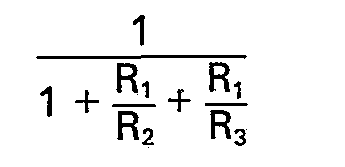
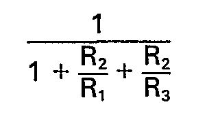
La valeur R4 de la résistance 21 et/ou la valeur Rs de la résistance 22 est faible par rapport à la valeur R3 de la résistance intégrée 19. Par exemple:![]()
![]()
Grâce à la liaison entre une borne de la résistance 10 et l'entrée inverseuse de l'amplificateur 17, on effectue une contre-réaction appelée contre-réaction dynamique permettant d'asservir le courant traversant le déviateur 8 au signal produit par l'oscillateur 14 auquel est superposé le signal de correction produit par le générateur 13.Thanks to the connection between a terminal of the resistor 10 and the inverting input of the
La liaison à filtre passe-bas 23 et résistance 24 permet d'effectuer une contre-réaction, dite contre-réaction statique, qui assure une valeur constante, grâce à la constance de la tension Vref, à la valeur moyenne de la tension aux bornes du condensateur de liaison 9.The link with low-
On va maintenant montrer que chaque tension parvenant au point 16 est affectée d'un coefficient qui ne dépend que du rapport entre des valeurs de résistances de même nature (intégrée ou discrète).We will now show that each voltage arriving at point 16 is assigned a coefficient which only depends on the ratio between resistance values of the same nature (integrated or discrete).
La tension V au point de sommation 16 a la valeur suivante:![]()
![]()
Dans cette formule Vosc est le signal de tension à la sortie de l'oscillateur 14, Vst est le signal de tension à la sortie du filtre 23, Vmes est le signal de tension à la borne de la résistance 22 opposée au point 20, et Vcor est le signal à la sortie du générateur 13.In this formula Vosc is the voltage signal at the output of
Les coefficients a1, a2, a4 et a5 ont les valeurs suivantes:![]()

![]()
![]()
![]()
![]()
![]()
R4//R5 est la valeur de la résistance équivalente aux résistances 21 et 22 en parallèle, c'est-à-dire:![]()
![]()
![]()
![]()
Rs étant petit devant R3 et la résistance équivalente aux résistances de valeurs respectives R4 et Rs en parallèle ayant une valeur plus faible que Rs, la valeur de cette résistance équivalente est, à fortiori, petite par rapport à R3. Dans ces conditions la quantité![]()
![]()
![]()
![]()
De ce résultat, on déduit:
- le coefficient a, est peu différent de


- the coefficient a, is little different from
On voit ainsi que les coefficients a1 et a2 ne dépendent que de rapports entre valeurs de résistances intégrées. Ces coefficients peuvent donc être déterminés avec précision.It can thus be seen that the coefficients a 1 and a 2 depend only on the relationships between integrated resistance values. These coefficients can therefore be determined with precision.
Les coefficients a4 et a5 sont chacuns le produit de deux termes dont le premier ne dépend que du rapport entre les valeurs de résistances discrètes et dont le second ne dépend que du rapport entre des valeurs de résistances intégrées. Il en résulte que ces coefficients a4 et as peuvent également être déterminés avec précision.The coefficients a 4 and a5 are each the product of two terms, the first of which depends only on the ratio between the values of discrete resistances and the second of which only depends on the ratio of the values of integrated resistances. As a result, these coefficients a 4 and a s can also be determined with precision.
Ainsi le taux de correction dont sera affecté le signal en dents de scie produit par l'oscillateur 14 pourra être modifié par modification de Rs ou R4, c'est-à-dire en agissant sur les valeurs d'éléments discrets. On a constaté que ce taux de correction pouvait alors être modifié dans une gamme supérieure à celle nécessaire pour la correction des tubes cathodiques et cela sans altération des performances des circuits de contre-réaction, respectivement statique et dynamique. En outre, le nombre des composants externes au circuit intégré 12 est réduit à un minimum.Thus, the correction rate with which the sawtooth signal produced by the
Si le récepteur de télévision est tel qu'il peut fonctionner sans correction, le générateur 13 et la résistance 21 pourront être supprimés et la résistance 22 pourra être remplacée par un simple fil de liaison.If the television receiver is such that it can operate without correction, the generator 13 and the resistor 21 can be deleted and the
En variante encore le générateur 13 fait partie du circuit intégré 12, les résistances 21 et 22 étant cependant sous forme discrète pour permettre de modifier leurs valeurs afin de modifier le taux de correction par exemple pour l'adapter au type de tube utilisé.In another variant, the generator 13 is part of the integrated circuit 12, the
Claims (11)
Applications Claiming Priority (2)
| Application Number | Priority Date | Filing Date | Title |
|---|---|---|---|
| FR8027322A FR2496933A1 (en) | 1980-12-23 | 1980-12-23 | VOLTAGE ADDITER AND VERTICAL SCANNING DEVICE AND TELEVISION RECEIVER HAVING SUCH ADDITIONER |
| FR8027322 | 1980-12-23 |
Publications (2)
| Publication Number | Publication Date |
|---|---|
| EP0055148A1 EP0055148A1 (en) | 1982-06-30 |
| EP0055148B1 true EP0055148B1 (en) | 1984-09-12 |
Family
ID=9249405
Family Applications (1)
| Application Number | Title | Priority Date | Filing Date |
|---|---|---|---|
| EP19810401756 Expired EP0055148B1 (en) | 1980-12-23 | 1981-10-30 | Voltage adder and vertical scanning device, and television receiver comprising such an adder |
Country Status (4)
| Country | Link |
|---|---|
| EP (1) | EP0055148B1 (en) |
| DE (1) | DE3166075D1 (en) |
| ES (1) | ES8302930A1 (en) |
| FR (1) | FR2496933A1 (en) |
Families Citing this family (2)
| Publication number | Priority date | Publication date | Assignee | Title |
|---|---|---|---|---|
| DE3711173A1 (en) * | 1987-04-02 | 1988-10-20 | Thomson Brandt Gmbh | LINE DISPLAY CIRCUIT FOR A PICTURE TUBE |
| US5856836A (en) * | 1995-04-12 | 1999-01-05 | Eastman Kodak Company | Coincident drop selection, drop separation printing method and system |
Family Cites Families (2)
| Publication number | Priority date | Publication date | Assignee | Title |
|---|---|---|---|---|
| DE2116431A1 (en) * | 1971-04-03 | 1972-10-12 | Philips Patentverwaltung | Circuit arrangement for electron beam deflection |
| FR2438395A1 (en) * | 1978-07-27 | 1980-04-30 | Thomson Brandt | SWITCHED FRAME SCANNING CIRCUIT, AND VIDEO FREQUENCY RECEIVER PROVIDED WITH SUCH A CIRCUIT |
-
1980
- 1980-12-23 FR FR8027322A patent/FR2496933A1/en active Granted
-
1981
- 1981-10-30 DE DE8181401756T patent/DE3166075D1/en not_active Expired
- 1981-10-30 EP EP19810401756 patent/EP0055148B1/en not_active Expired
- 1981-12-22 ES ES508242A patent/ES8302930A1/en not_active Expired
Also Published As
| Publication number | Publication date |
|---|---|
| FR2496933A1 (en) | 1982-06-25 |
| FR2496933B1 (en) | 1984-07-06 |
| EP0055148A1 (en) | 1982-06-30 |
| DE3166075D1 (en) | 1984-10-18 |
| ES508242A0 (en) | 1982-12-01 |
| ES8302930A1 (en) | 1982-12-01 |
Similar Documents
| Publication | Publication Date | Title |
|---|---|---|
| EP3814782B1 (en) | Current sensor with flux gate | |
| EP0452557A1 (en) | Signal level measuring circuit including correction means | |
| EP0055148B1 (en) | Voltage adder and vertical scanning device, and television receiver comprising such an adder | |
| EP0810728A1 (en) | Analog audio filter for high frequencies | |
| EP0004498B1 (en) | Apparatus for generating the cut-off voltage of a cathode-ray-tube and colour television receiver embodying such an apparatus | |
| EP0011533B1 (en) | Sawtooth generator circuit, especially for line deflection in a cathode-ray tube and device comprising such a circuit | |
| EP0465349B1 (en) | Device for gamma correcting an analog video signal | |
| EP0490711B1 (en) | Electrical measuring device with two configurations of connection | |
| EP0071294B1 (en) | Frequency demodulator | |
| EP0358145B1 (en) | Screened tension-measuring appliance for a triphase installation | |
| GÜNES et al. | Realization of voltage and current-mode transfer functions using unitygain cells | |
| US5212378A (en) | Optical receiver with critical damping resistor | |
| EP0722247B1 (en) | Emphasis and de-emphasis circuit | |
| EP0024223B1 (en) | Vertical deflection signal precorrection circuit for a display tube and television receiver comprising such a circuit | |
| EP0699359B1 (en) | Polarization current controlled electronic circuit such as an adjustable resistance, a negative resistance or a filter or similar | |
| EP0038240A1 (en) | D.C. power supply and its use to feed a cathodic tube | |
| US5268575A (en) | Infrared observing system | |
| FR2543761A1 (en) | INDUCTIVE FILTER OF ELECTRIC SIGNALS HAVING REDUCED IMPEDANCE | |
| EP0086158B1 (en) | Supply circuit for an eddy current probe | |
| FR2515906A1 (en) | TELEVISION LINE DEVIATION CIRCUIT | |
| EP0083529A2 (en) | Amplifier arrangement for large voltage swing, and voltage source with such an arrangement | |
| EP0103520B1 (en) | Input and supply circuit for a filter, especially a filter for a centralized remote control receiver | |
| EP0055152B1 (en) | Vertical deflection circuit, power supply for its control and television receiver comprising such a circuit | |
| EP0226490A1 (en) | Synchronous switched-capacitor filter | |
| EP1131890B1 (en) | Digital-to-analog converter |
Legal Events
| Date | Code | Title | Description |
|---|---|---|---|
| PUAI | Public reference made under article 153(3) epc to a published international application that has entered the european phase |
Free format text: ORIGINAL CODE: 0009012 |
|
| AK | Designated contracting states |
Designated state(s): DE GB |
|
| 17P | Request for examination filed |
Effective date: 19820710 |
|
| RAP1 | Party data changed (applicant data changed or rights of an application transferred) |
Owner name: SOCIETE D'ELECTRONIQUE DE LA REGION PAYS DE LOIRE |
|
| RBV | Designated contracting states (corrected) |
Designated state(s): DE GB |
|
| GRAA | (expected) grant |
Free format text: ORIGINAL CODE: 0009210 |
|
| AK | Designated contracting states |
Designated state(s): DE GB |
|
| REF | Corresponds to: |
Ref document number: 3166075 Country of ref document: DE Date of ref document: 19841018 |
|
| PLBE | No opposition filed within time limit |
Free format text: ORIGINAL CODE: 0009261 |
|
| STAA | Information on the status of an ep patent application or granted ep patent |
Free format text: STATUS: NO OPPOSITION FILED WITHIN TIME LIMIT |
|
| 26N | No opposition filed | ||
| PGFP | Annual fee paid to national office [announced via postgrant information from national office to epo] |
Ref country code: DE Payment date: 19920917 Year of fee payment: 12 |
|
| PGFP | Annual fee paid to national office [announced via postgrant information from national office to epo] |
Ref country code: GB Payment date: 19920918 Year of fee payment: 12 |
|
| PG25 | Lapsed in a contracting state [announced via postgrant information from national office to epo] |
Ref country code: GB Effective date: 19931030 |
|
| GBPC | Gb: european patent ceased through non-payment of renewal fee |
Effective date: 19931030 |
|
| PG25 | Lapsed in a contracting state [announced via postgrant information from national office to epo] |
Ref country code: DE Effective date: 19940701 |