EP0055075A2 - Needle position detector - Google Patents
Needle position detector Download PDFInfo
- Publication number
- EP0055075A2 EP0055075A2 EP81305909A EP81305909A EP0055075A2 EP 0055075 A2 EP0055075 A2 EP 0055075A2 EP 81305909 A EP81305909 A EP 81305909A EP 81305909 A EP81305909 A EP 81305909A EP 0055075 A2 EP0055075 A2 EP 0055075A2
- Authority
- EP
- European Patent Office
- Prior art keywords
- disk
- members
- light
- needle
- shaft
- Prior art date
- Legal status (The legal status is an assumption and is not a legal conclusion. Google has not performed a legal analysis and makes no representation as to the accuracy of the status listed.)
- Withdrawn
Links
Images

Classifications
-
- D—TEXTILES; PAPER
- D05—SEWING; EMBROIDERING; TUFTING
- D05B—SEWING
- D05B69/00—Driving-gear; Control devices
- D05B69/22—Devices for stopping drive when sewing tools have reached a predetermined position
- D05B69/24—Applications of devices for indicating or ascertaining sewing-tool position
Definitions
- TITLE NEEDLE POSITION DETECTOR
- the present invention relates generally to industrial sewing machines, and in particular to a needle position detector.
- the needle position detector plays an important role of an industrial sewing machine due to the fact that the needle position information is used to control the solenoid-operated clutch and brake arrangement which is essential to a variety of industrial sewing functions including variable speed control and stoppage at desired needle positions. A high degree of precision and reliability is thus required of the needle position detector to meet the requirements of the industrial application.
- the detector In order to monitor the instantaneous position of the needle, the detector is connected to the armshaft of the sewing machine with which the needle is driven and mounted on the sewing machine head. Being located in a position adjacent to the operator, the detector is required to be compact in design to allow space for sewing operations.
- Conventional needle position detectors can be classified into a number of types including an electromagnetic system, oscillator type and an electrooptical system.
- an electromagnetic system a permanent magnet is attached to a rotary part of the sewing machine so that its opposite poles correspond respectively to the upper and lower needle positions and a Hall generator is mounted stationarily with rspect to the magnet.
- a ferromagnetic member is attached to the rotary part and the permanent magnet and Hall generator are mounted stationarily with respect to the rotating ferromagnetic member to generate a signal as the latter traverses the magnetic flux.
- Needle position detectors of the oscillator type comprise a flux generating coil and a sensing coil which are mounted in an oppositely facing relation, and a slitted rotary iron disk which is arranged to rotate through the space between the two coils to alter the frequency of oscillation.
- Needle position detectors of the optoelectrical type currently include a set of a light emitting and sensitive elements which are facing to each other and between which is provided a rotary interrupter. However, in either of these prior art systems it is difficult to achieve compactness.
- the present invention eliminates the aforesaid prior art problem by arranging a pair of disk-like members axially on a rotary shaft which is coupled to the armshaft for unitary rotation therewith, each of the disk-like members having an optically nonreflective portion occupying a greater circumferential area and an optically reflective portion occupying a smaller circumferential area.
- the optically reflective portions are positioned so that they are respectively associated with the upper and lower needle positions.
- a pair of light emitting elements is mounted stationarily so that the elements are associated with the disk-like members to direct light rays respectively to the reflecting portions of the disk-like members.
- a pair of light sensitive elements is located adjacent to the light emitting elements to receive light rays reflected respectively from the reflecting portions of the disk-like members to generate signals indicative of the upper and lower needle positions.
- the needle position detector allows ease with which the detector is precisely and quickly adjusted.
- the ease of adjustement feature is accomplished by the optically nonreflective portions of the disk-like members which extend a substantial area over the associated light sensitive elements. This serves to keep external light rays from interfering with the light sensitive elements.
- the detector further comprises a spring for urging the disk-like members in directions away from each other, a holding member axially movably mounted on the rotary shaft adjacent to one of the disk-like members and a screw threadably engaged with one end of the shaft for engaging the holding member with the adjacent disk-like member, whereby the disk-like members are resiliently held together when the screw is loosened for angular position adjustment.
- each of the disk-like members and holding member is axially movable but not rotatable with respect to the shaft when the screw is loosened for adjustment.
- This arrangement serves to keep one disk-like member from freely rotating while the other member is being adjusted.
- Fig. 1 there is shown a preferred embodiment of the needle position detector of the invention which, for the purpose of illustration, incorporates a sewing speed detector in a common housing.
- the sewing speed detector comprises a rotor shaft 1 rigidly fixed to a sewing machine pulley, not shown, by secrews 29 and thence to the armshaft of the sewing machine.
- the rotor shaft 1 extends axially through a bearing 3 into a resin moulded housing 2 fixed to the sewing machine head (not shown).
- a pair of ring-shaped yokes 4 and 5, each composed of iron or any magnetic material, is rigidly secured to the housing 2 by screws 12 so that yoke 4 bears against an end wall of the bearing 3 to hold it in position.
- ring-shaped permanent magnets 6 and 7, respectively are provided in the yokes 4 and 5 ring-shaped permanent magnets 6 and 7, respectively.
- the permanent magnets 6 and 7 are magnetized so that the north pole of the former is on its right side and the north pole of the latter is on its left side.
- a ring-shaped stator core 8 having a plurality of teeth on its inner periphery.
- Ring-shaped stator coils 10 and 11 are fixed to the yokes 4 and 5 respectively within the inner walls of the permanent magnets 6 and 7.
- a toothed rotor wheel 9 which is fixed to the rotor shaft 1 by yokes or spacers 13 and 14.
- the operation of the speed detector is as follows.
- the magnetic fluxes generated by the permanent magnets 6 and 7 pass through a common path formed by stator core 8 and rotor wheel 9 with the flux produced by magnet 6 passing through spacer 13 and yoke 4 crossing the ring coil 10 and the flux produced by magnet 7 passing through spacer 14 and yoke 5 to cross the ring coil 11. Since the magnetic flux passes through the variable spacing formed between the teeth of stator core 8 and rotor wheel 9, the reluctance value of the magnetic circuit varies at periodic intervals so that a voltage is induced in the coils 10 and 11 at a frequency related to the sewing speed.
- the stator core 8 and rotor wheel 9 forms the common magnetic circuit, the variations in the reluctance value occur simultaneously in the two magnetic circuits. Therefore, the voltage induced in the coil 10 is reverse in polarity to the voltage induced in the coil 11.
- the coils 10 and 11 are connected in series so that the voltages so generated are constructively added and supplied to the amplifier and thence to a waveshaping circuit to generate a train of rectangular pulses at a frequency inversely proportional to the speed of the sewing machine.
- the needle position detector includes a pair of first and second disks 15 and 16 adjustably mounted on the rotor shaft 1 and having at their circumference light reflecting members 15A and 16A which extend in axially opposite directions to each other.
- the light reflecting members 15A, 16A are composed of a material which stays reflective for extended periods such as stainless steel or iron plate electroplated with chromium.
- a pair of optoelectrical devices 17 and 18 is stationarily disposed in a resin block 19 on a printed circuit board 25 with respect to the light reflecting members 15A and 16A.
- Each optoelectrical device includes a light emitting element and a light receiving element which are designated by characters "A" and "B", respectively, attached to the numerals 17 and 18.
- the optoelectrical devices 17, 18 are preferably of the type which employs infrared light instead of visible light and a filter which allows the light receiving elements to respond exclusively to infrared light.
- the rotary disks 15 and 16 are spaced apart by a pair of moulded resin spacers 20 and 21 in the shape of a ring. Each spacer is formed with an annular groove in which a compression spring 22 is provided.
- the spacers 20 and 21 are composed of a black resinous material to present an optically nonreflecive surface to incident light. This nonreflective surface extends over the light receiving elements to keep them from being interfered with unwanted light rays.
- the disks 15 and 16 are adjusted so that their reflective members are angularly positioned to correspond to the upper and lower needle positions, respectively.
- the disk 15 with its optically reflective member 15A and spacer 20 constitute a first disk-like member having an optically nonreflective portion occupying a greater circumferential area as provided by spacer 20 and an optically reflective portion occupying a smaller circumferential area as provided by the reflective member 15A.
- the disk 16 with its reflective member 16A and spacer 21 constitute a second disk-like member having a second optically nonreflective portion occupying a greater circumferential area as provided by spacer 21 and an optically reflective portion occupying a smaller circumferential area as provided by the reflective member 16A.
- the needle position detector of the invention can fit into a relatively small area. As will be understood as description will proceed, the manual adjustment of the detector is made with ease inspite of the reduced size.
- the light reflective members 15A and 16A each have an radial extent greater than the radial extent of each spacer so that the reflective members are closer to the electrooptical devices 17 and 18. This eliminates the use of lenses for forming the emitted light into a narrow beam, which would only add extra cost.
- a moulded resin holding member 23 is adjustably fixed to the distal end of the rotor shaft 1 by means of an adjustment screw 24 to axially clamp the disks 15 and 16.
- a cover 27 On the printed circuit board 25 are mounted an amplifier and other auxiliary circuits which are coupled to transmit needle position signals to external control circuitry by a cable 28 which is clamped in position by a resin mould 26 which forms part of the housing 2. The whole unit is enclosed by a cover 27.
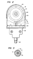
- Fig. 2 is an illustration of an end view seen from the right side of the needle position detector with the cover 27 being removed to make the inside visible.
- the disk 16 is formed with a plurality of slits 16B at the circumference thereof to permit a screwdriver to extend therethrough in a manner as will be described later.
- the light reflecting member 16A has an arcuate extent of approproximately 30 degrees on the circumference of the rotary disk 16.
- the light emitting elements 17A and 18A are constantly energized to emit light rays which are reflected from reflecting members 15A and 16A as they come to their downward positions to the light receiving elements 17B and 18B. Needle position signals are thus generated when the sewing needle comes to upper and.lower positions.
- the light reflecting members 15A and 16A are displaced from their downward positions, the emitted light is absorbed by the nonreflective surface of the spacer 20 or 21.
- the nonreflective surface provided by the spacers 20, 21 extends a substantial area over the light sensitive elements, external light is successfully kept from interfering such elements. Furthermore, since the external light, either from natural or artifical source, has a lesser amount of components in the infrared light region, the use of infrared electrooptical devices 17, 18 renders them less susceptible to such external light.
- a needle-down position adjustment is accomplished by positioning the light reflecting member 15A to its downward position with the needle being positioned downward, while a needle-up position adjustment is achieved by positioning the light reflecting member 16A in its downward position with the needle being positioned upward. It is seen that needle-up and needle-down position adjustments can be effected independently of each other. However, after the manual adjustment has been made with respect to one of the light reflecting members, it is necessary that this adjusted member be held rigidly in position while the other member is subsequently adjusted. This is accomplished by the provision of an axially extending groove 31, as illustrated in Fig. 3, on the rotor shaft 1 and corresponding lugs 32 on the inner wall of the spacers 20, 21 and holding plate 23 so that the latter is axially movable but not rotatable with respect to the rotor shaft 1.
- the purpose of the spring 22 is to resiliently hold the light reflecting disks 15 and 16 together to keep their relative angular positions when the screw 24 is loosened for adjustment.
- the angular positon of the disk 16 can be adjusted with a screwdriver by engaging it with one of its recesses 16B, while the oppositely biased spacers 20 and 21 keep the other disk 15 from becoming loosened.
- the screw 24 is tightened and in doing so the holding plate 23 is only allowed to move axially but not rotatable with the screw 24 thus preventing the disk 16 from being displaced from the right angular position.
Landscapes
- Engineering & Computer Science (AREA)
- Mechanical Engineering (AREA)
- Textile Engineering (AREA)
- Sewing Machines And Sewing (AREA)
- Optical Transform (AREA)
Abstract
Description
- The present invention relates generally to industrial sewing machines, and in particular to a needle position detector.
- The needle position detector plays an important role of an industrial sewing machine due to the fact that the needle position information is used to control the solenoid-operated clutch and brake arrangement which is essential to a variety of industrial sewing functions including variable speed control and stoppage at desired needle positions. A high degree of precision and reliability is thus required of the needle position detector to meet the requirements of the industrial application. In order to monitor the instantaneous position of the needle, the detector is connected to the armshaft of the sewing machine with which the needle is driven and mounted on the sewing machine head. Being located in a position adjacent to the operator, the detector is required to be compact in design to allow space for sewing operations.
- Conventional needle position detectors can be classified into a number of types including an electromagnetic system, oscillator type and an electrooptical system. In the electromagnetic system a permanent magnet is attached to a rotary part of the sewing machine so that its opposite poles correspond respectively to the upper and lower needle positions and a Hall generator is mounted stationarily with rspect to the magnet. In another electromagnetic system, a ferromagnetic member is attached to the rotary part and the permanent magnet and Hall generator are mounted stationarily with respect to the rotating ferromagnetic member to generate a signal as the latter traverses the magnetic flux. However, shortcomings inherent in such electromagnetic systems are difficulty in determining the critical value of magnetic flux since a lower critical value will render the detector less immune to external magnetic flux and a higher critical value will require the use of a permanent magnet containing a costly rare earth element. Arranging the permanent magnet so that its opposite poles rotate at 180 degrees apart, while advantageous for keeping the size of the detector to a minimum, is disadvantageous due to the fact that for detecting upper and lower needle positions two of such magnet are required which must be spaced a distance sufficient to allow the Hall generator to sharply distinguish between adjacent poles. In another prior art electromagnetic detector, the magnet and Hall generator are mounted on a stationary support between which a slitted iron rotary disk is arranged to rotate to act as an interceptor. This type of system requires that the magnet and Hall generator be spaced a substantial distance apart for satisfactory operation and that the magnet be composed of a costly rare earth element to generate a strong magnetic field. Thus, the goal of compactness and economy has not yet been accomplished with conventional needle position detectors of the magnetic type.
- Needle position detectors of the oscillator type, on the other hand, comprise a flux generating coil and a sensing coil which are mounted in an oppositely facing relation, and a slitted rotary iron disk which is arranged to rotate through the space between the two coils to alter the frequency of oscillation. Needle position detectors of the optoelectrical type currently include a set of a light emitting and sensitive elements which are facing to each other and between which is provided a rotary interrupter. However, in either of these prior art systems it is difficult to achieve compactness.
- The problem of compactness is compounded by the fact that industrial sewing machines are operated in a wide range of speeds according to the depression of a foot pedal and this operating speed must be controlled with a high precision in a closed loop by sensing the actual speed of the sewing machine. Being coupled to the armshaft, the speed sensor reduces the space allowed for the needle position detector.
- The present invention eliminates the aforesaid prior art problem by arranging a pair of disk-like members axially on a rotary shaft which is coupled to the armshaft for unitary rotation therewith, each of the disk-like members having an optically nonreflective portion occupying a greater circumferential area and an optically reflective portion occupying a smaller circumferential area. The optically reflective portions are positioned so that they are respectively associated with the upper and lower needle positions. A pair of light emitting elements is mounted stationarily so that the elements are associated with the disk-like members to direct light rays respectively to the reflecting portions of the disk-like members. A pair of light sensitive elements is located adjacent to the light emitting elements to receive light rays reflected respectively from the reflecting portions of the disk-like members to generate signals indicative of the upper and lower needle positions.
- According to a feature of the present invention, the needle position detector allows ease with which the detector is precisely and quickly adjusted. The ease of adjustement feature is accomplished by the optically nonreflective portions of the disk-like members which extend a substantial area over the associated light sensitive elements. This serves to keep external light rays from interfering with the light sensitive elements. The detector further comprises a spring for urging the disk-like members in directions away from each other, a holding member axially movably mounted on the rotary shaft adjacent to one of the disk-like members and a screw threadably engaged with one end of the shaft for engaging the holding member with the adjacent disk-like member, whereby the disk-like members are resiliently held together when the screw is loosened for angular position adjustment.
- Preferably, each of the disk-like members and holding member is axially movable but not rotatable with respect to the shaft when the screw is loosened for adjustment. This arrangement serves to keep one disk-like member from freely rotating while the other member is being adjusted.
- The present invention will be described in further detail with reference to the accompanying drawings, in which:
- Fig. 1 is a cross-setional view of a preferred embodiment of the needle position detector of the invention shown mounted in a common housing with a speed detector;
- Fig. 2 is an end view of the needle position detector with a cover being removed; and
- Fig. 3 is a cross-sectional view taken along the line 3-3 of Fig. 1.
- Referring now to Fig. 1, there is shown a preferred embodiment of the needle position detector of the invention which, for the purpose of illustration, incorporates a sewing speed detector in a common housing.
- Before proceeding to a description of the needle position detector, it is appropriate to describe the speed detector with which the needle position detector of the invention is connected. The sewing speed detector comprises a
rotor shaft 1 rigidly fixed to a sewing machine pulley, not shown, bysecrews 29 and thence to the armshaft of the sewing machine. Therotor shaft 1 extends axially through abearing 3 into a resin mouldedhousing 2 fixed to the sewing machine head (not shown). A pair of ring-shaped yokes 4 and 5, each composed of iron or any magnetic material, is rigidly secured to thehousing 2 byscrews 12 so that yoke 4 bears against an end wall of thebearing 3 to hold it in position. In theyokes 4 and 5 are provided ring-shapedpermanent magnets 6 and 7, respectively. Thepermanent magnets 6 and 7 are magnetized so that the north pole of the former is on its right side and the north pole of the latter is on its left side. Between thepermanent magnets 6 and 7 is a ring-shaped stator core 8 having a plurality of teeth on its inner periphery. Ring-shaped stator coils 10 and 11 are fixed to theyokes 4 and 5 respectively within the inner walls of thepermanent magnets 6 and 7. Between thering coils 10 and 11 is a toothed rotor wheel 9 which is fixed to therotor shaft 1 by yokes orspacers - The operation of the speed detector is as follows. The magnetic fluxes generated by the
permanent magnets 6 and 7 pass through a common path formed bystator core 8 and rotor wheel 9 with the flux produced by magnet 6 passing throughspacer 13 and yoke 4 crossing the ring coil 10 and the flux produced bymagnet 7 passing throughspacer 14 andyoke 5 to cross thering coil 11. Since the magnetic flux passes through the variable spacing formed between the teeth ofstator core 8 and rotor wheel 9, the reluctance value of the magnetic circuit varies at periodic intervals so that a voltage is induced in thecoils 10 and 11 at a frequency related to the sewing speed. Since thestator core 8 and rotor wheel 9 forms the common magnetic circuit, the variations in the reluctance value occur simultaneously in the two magnetic circuits. Therefore, the voltage induced in the coil 10 is reverse in polarity to the voltage induced in thecoil 11. Thecoils 10 and 11 are connected in series so that the voltages so generated are constructively added and supplied to the amplifier and thence to a waveshaping circuit to generate a train of rectangular pulses at a frequency inversely proportional to the speed of the sewing machine. - Description of the needle position detector will follow. The needle position detector includes a pair of first and
second disks rotor shaft 1 and having at their circumferencelight reflecting members light reflecting members optoelectrical devices resin block 19 on a printedcircuit board 25 with respect to thelight reflecting members numerals optoelectrical devices rotary disks moulded resin spacers compression spring 22 is provided. Thespacers disks - It is seen that the
disk 15 with its opticallyreflective member 15A andspacer 20 constitute a first disk-like member having an optically nonreflective portion occupying a greater circumferential area as provided byspacer 20 and an optically reflective portion occupying a smaller circumferential area as provided by thereflective member 15A. Thedisk 16 with itsreflective member 16A andspacer 21 constitute a second disk-like member having a second optically nonreflective portion occupying a greater circumferential area as provided byspacer 21 and an optically reflective portion occupying a smaller circumferential area as provided by thereflective member 16A. Due to the axial arrangement of the light reflecting disk-like members and the radial arrangement of the electrooptical sensing devices with respect to therotor shaft 1, the needle position detector of the invention can fit into a relatively small area. As will be understood as description will proceed, the manual adjustment of the detector is made with ease inspite of the reduced size. - The light
reflective members electrooptical devices - A moulded
resin holding member 23 is adjustably fixed to the distal end of therotor shaft 1 by means of anadjustment screw 24 to axially clamp thedisks - On the printed
circuit board 25 are mounted an amplifier and other auxiliary circuits which are coupled to transmit needle position signals to external control circuitry by acable 28 which is clamped in position by aresin mould 26 which forms part of thehousing 2. The whole unit is enclosed by acover 27. - Fig. 2 is an illustration of an end view seen from the right side of the needle position detector with the
cover 27 being removed to make the inside visible. As seen in Fig. 2, thedisk 16 is formed with a plurality ofslits 16B at the circumference thereof to permit a screwdriver to extend therethrough in a manner as will be described later. Thelight reflecting member 16A has an arcuate extent of approproximately 30 degrees on the circumference of therotary disk 16. - The
light emitting elements 17A and 18A are constantly energized to emit light rays which are reflected from reflectingmembers light receiving elements light reflecting members spacer - Since the nonreflective surface provided by the
spacers electrooptical devices - Description will now be concerned with manual adjustment of the
disks cover 27 being removed. - A needle-down position adjustment is accomplished by positioning the
light reflecting member 15A to its downward position with the needle being positioned downward, while a needle-up position adjustment is achieved by positioning thelight reflecting member 16A in its downward position with the needle being positioned upward. It is seen that needle-up and needle-down position adjustments can be effected independently of each other. However, after the manual adjustment has been made with respect to one of the light reflecting members, it is necessary that this adjusted member be held rigidly in position while the other member is subsequently adjusted. This is accomplished by the provision of anaxially extending groove 31, as illustrated in Fig. 3, on therotor shaft 1 andcorresponding lugs 32 on the inner wall of thespacers plate 23 so that the latter is axially movable but not rotatable with respect to therotor shaft 1. - The purpose of the
spring 22 is to resiliently hold thelight reflecting disks screw 24 is loosened for adjustment. With this arrangement the angular positon of thedisk 16 can be adjusted with a screwdriver by engaging it with one of itsrecesses 16B, while the oppositely biasedspacers other disk 15 from becoming loosened. - After both disks have been adjusted to right positions, the
screw 24 is tightened and in doing so the holdingplate 23 is only allowed to move axially but not rotatable with thescrew 24 thus preventing thedisk 16 from being displaced from the right angular position.
Claims (6)
Applications Claiming Priority (2)
| Application Number | Priority Date | Filing Date | Title |
|---|---|---|---|
| JP180664/80 | 1980-12-19 | ||
| JP55180664A JPS57103679A (en) | 1980-12-19 | 1980-12-19 | Detector for position of sewing-machine needle |
Publications (2)
| Publication Number | Publication Date |
|---|---|
| EP0055075A2 true EP0055075A2 (en) | 1982-06-30 |
| EP0055075A3 EP0055075A3 (en) | 1982-09-22 |
Family
ID=16087147
Family Applications (1)
| Application Number | Title | Priority Date | Filing Date |
|---|---|---|---|
| EP81305909A Withdrawn EP0055075A3 (en) | 1980-12-19 | 1981-12-16 | Needle position detector |
Country Status (5)
| Country | Link |
|---|---|
| US (1) | US4463698A (en) |
| EP (1) | EP0055075A3 (en) |
| JP (1) | JPS57103679A (en) |
| KR (1) | KR840001542B1 (en) |
| CA (1) | CA1183923A (en) |
Cited By (1)
| Publication number | Priority date | Publication date | Assignee | Title |
|---|---|---|---|---|
| US4665843A (en) * | 1985-04-10 | 1987-05-19 | Durkoppwerke Gmbh | Sewing device for producing piped openings in sewing material |
Families Citing this family (7)
| Publication number | Priority date | Publication date | Assignee | Title |
|---|---|---|---|---|
| US4987842A (en) * | 1981-07-10 | 1991-01-29 | Mitsubishi Denki Kabushiki Kaisha | Detector for use on sewing machine |
| US4584954A (en) * | 1981-07-10 | 1986-04-29 | Mitsubishi Denki Kabushiki Kaisha | Detector for use on sewing machines |
| JPH0221010Y2 (en) * | 1985-11-29 | 1990-06-07 | ||
| DE3600938C1 (en) * | 1986-01-15 | 1987-08-06 | Pfaff Haushaltmasch | Impulse generator for a sewing machine drive |
| DE19702391C1 (en) * | 1997-01-24 | 1997-10-02 | Duerkopp Adler Ag | Setting-up apparatus for a sewing machine |
| US6116320A (en) | 1999-01-09 | 2000-09-12 | Barker Holding Company, Llc | Automatic window shade system |
| US6409143B1 (en) | 2000-02-02 | 2002-06-25 | Ewc Controls Incorporated | Damper assembly with an electro-optical controller for positioning the damper vanes |
Family Cites Families (6)
| Publication number | Priority date | Publication date | Assignee | Title |
|---|---|---|---|---|
| NL275057A (en) * | 1961-02-21 | |||
| DE1907975C3 (en) * | 1969-02-18 | 1975-03-27 | Frankl & Kirchner, Fabrik Fuer Elektromotoren U. Elektrische Apparate, 6830 Schwetzingen | Contact-free synchronizer |
| SE356770B (en) * | 1971-10-05 | 1973-06-04 | Asea Ab | |
| JPS5714875B2 (en) * | 1973-03-23 | 1982-03-26 | ||
| US3990374A (en) * | 1975-03-28 | 1976-11-09 | Frankl & Kirchner | Contactless synchronizer for sewing machines |
| US4269132A (en) * | 1978-01-13 | 1981-05-26 | Hsu Yung San | Position indicating unit for sewing machines |
-
1980
- 1980-12-19 JP JP55180664A patent/JPS57103679A/en active Pending
-
1981
- 1981-07-13 KR KR1019810002537A patent/KR840001542B1/en not_active Expired
- 1981-12-16 EP EP81305909A patent/EP0055075A3/en not_active Withdrawn
- 1981-12-16 US US06/331,329 patent/US4463698A/en not_active Expired - Lifetime
- 1981-12-18 CA CA000392695A patent/CA1183923A/en not_active Expired
Cited By (1)
| Publication number | Priority date | Publication date | Assignee | Title |
|---|---|---|---|---|
| US4665843A (en) * | 1985-04-10 | 1987-05-19 | Durkoppwerke Gmbh | Sewing device for producing piped openings in sewing material |
Also Published As
| Publication number | Publication date |
|---|---|
| EP0055075A3 (en) | 1982-09-22 |
| KR830006516A (en) | 1983-09-28 |
| JPS57103679A (en) | 1982-06-28 |
| CA1183923A (en) | 1985-03-12 |
| US4463698A (en) | 1984-08-07 |
| KR840001542B1 (en) | 1984-10-04 |
Similar Documents
| Publication | Publication Date | Title |
|---|---|---|
| US3995156A (en) | Transmitter for governed-speed drives employing an optical grating and photocells at an angle thereto | |
| US4746791A (en) | Fiber optic sensor with an optical modulator having a permanent magnet for the detection of the movement or position of a magnetic component | |
| US5825178A (en) | Sensing device for determining an angular position of a steering wheel on a steering column in a vehicle | |
| US4455516A (en) | Brushless motor | |
| US4463698A (en) | Needle position detector | |
| US5160886A (en) | Permanent magnet resolver for producing a resolver-to-digital converter compatible output | |
| JP4592435B2 (en) | Small motor with encoder | |
| US4096419A (en) | Electric motors | |
| US4437061A (en) | Speed detector for sewing machines | |
| KR910001782B1 (en) | Electronic rectifier circuit device for excitation coil of DC motor | |
| US3213282A (en) | Photosensitive line tracing apparatus | |
| JPH07134047A (en) | Multi-turn encoder | |
| US7248038B2 (en) | Device for the detection of movements and/or positions of an object | |
| EP0191223A2 (en) | Magnetically-coupled transducer means | |
| US2798976A (en) | Timing signal generator | |
| US4539544A (en) | Detent mechanism for a hand-operated transducer | |
| JPS5718035A (en) | Optical recording and reproducing device | |
| US5184002A (en) | Optical scanner | |
| US6072296A (en) | Asynchronous motor for a drive mechanism, such as hoists or running gears, with controllable rotational speed and rotational direction | |
| US4740733A (en) | Autosynchronous motor comprising a device for determining the position of the rotor relative to the stator, and method of starting such motor | |
| US4906923A (en) | Speed detecting apparatus including a multi-coil device | |
| KR100237236B1 (en) | Head drum for a recorder | |
| JPH085409A (en) | Encoder | |
| DE59202845D1 (en) | Process for contactless control of the direction of rotation of electrical machines. | |
| KR100278451B1 (en) | Rotor position sensing device of switched reluctance motor |
Legal Events
| Date | Code | Title | Description |
|---|---|---|---|
| PUAI | Public reference made under article 153(3) epc to a published international application that has entered the european phase |
Free format text: ORIGINAL CODE: 0009012 |
|
| AK | Designated contracting states |
Designated state(s): DE FR GB |
|
| PUAL | Search report despatched |
Free format text: ORIGINAL CODE: 0009013 |
|
| AK | Designated contracting states |
Designated state(s): DE FR GB |
|
| 17P | Request for examination filed |
Effective date: 19830210 |
|
| STAA | Information on the status of an ep patent application or granted ep patent |
Free format text: STATUS: THE APPLICATION IS DEEMED TO BE WITHDRAWN |
|
| 18D | Application deemed to be withdrawn |
Effective date: 19850304 |
|
| RIN1 | Information on inventor provided before grant (corrected) |
Inventor name: NEKI, SHIGEO Inventor name: SHINOZAKI, NOZOMU Inventor name: DOHI, TAKASHI |