EP0054921A2 - Method for reducing print distortion of ink drop writing apparatus - Google Patents
Method for reducing print distortion of ink drop writing apparatus Download PDFInfo
- Publication number
- EP0054921A2 EP0054921A2 EP81110546A EP81110546A EP0054921A2 EP 0054921 A2 EP0054921 A2 EP 0054921A2 EP 81110546 A EP81110546 A EP 81110546A EP 81110546 A EP81110546 A EP 81110546A EP 0054921 A2 EP0054921 A2 EP 0054921A2
- Authority
- EP
- European Patent Office
- Prior art keywords
- drops
- ink
- ink drops
- writing
- uncharged
- Prior art date
- Legal status (The legal status is an assumption and is not a legal conclusion. Google has not performed a legal analysis and makes no representation as to the accuracy of the status listed.)
- Granted
Links
- 238000000034 method Methods 0.000 title claims abstract description 7
- 230000015572 biosynthetic process Effects 0.000 claims description 6
- 239000011159 matrix material Substances 0.000 claims description 5
- 230000007261 regionalization Effects 0.000 abstract description 6
- 230000005684 electric field Effects 0.000 abstract description 2
- 238000007796 conventional method Methods 0.000 description 1
- 238000010586 diagram Methods 0.000 description 1
- 230000005686 electrostatic field Effects 0.000 description 1
- 230000007274 generation of a signal involved in cell-cell signaling Effects 0.000 description 1
- 238000003780 insertion Methods 0.000 description 1
- 230000037431 insertion Effects 0.000 description 1
- 239000002699 waste material Substances 0.000 description 1
Images


Classifications
-
- B—PERFORMING OPERATIONS; TRANSPORTING
- B41—PRINTING; LINING MACHINES; TYPEWRITERS; STAMPS
- B41J—TYPEWRITERS; SELECTIVE PRINTING MECHANISMS, i.e. MECHANISMS PRINTING OTHERWISE THAN FROM A FORME; CORRECTION OF TYPOGRAPHICAL ERRORS
- B41J2/00—Typewriters or selective printing mechanisms characterised by the printing or marking process for which they are designed
- B41J2/005—Typewriters or selective printing mechanisms characterised by the printing or marking process for which they are designed characterised by bringing liquid or particles selectively into contact with a printing material
- B41J2/01—Ink jet
- B41J2/07—Ink jet characterised by jet control
- B41J2/075—Ink jet characterised by jet control for many-valued deflection
Definitions
- This invention relates to an ink drop writing apparatus and more particularly to an improved ink drop writing apparatus free from the print distortion.
- Apparatus has been developed for printing on a writing medium of the information represented by video signals by generating a stream of ink drops, directing these ink drops toward the writing medium, and then, deflecting the ink drops in response to the video signal, in a manner so that when the ink drops reach the writing medium, they provide a representation of the information contained in the video signals .
- the general apparatus employed for producing the ink drops consists of an ink reservoir in which there is ink under pressure. The ink reservoir feeds a pipe which is connected to a nozzle .
- An electromechanical transducer is employed to vibrate the pipe and the nozzle at some suitable high frequency which causes the ink to be injected from the nozzle in a stream which shortly thereafter breaks into individual drops.
- a charging tunnel through which the stream is projected, which serves the function of applying video signals to the individual drops .
- Downstream of the tunnel there is provided a pair of deflection plates which have a fixed potential thereacross.
- the electric field which is created between the plates acts on the charged drops causing them to be deflected in an amount determined by the amplitude of the charge on the drops.
- Downstream of the deflection plates is usually a nozzle or through for catching any drops which do not have any charge and transferring them to a waste reservoir.
- the writing medium which is to receive the deflected ink drops, which thereby form the images representative of the video signals.
- the writing medium is usually moved in synchronism with the application of video signals to the drops .
- the ink drops are not able to be given a desired amount of charge and deflection and therefore form writing dots on positions deviated from the correct positions.
- the writing deformation occurs .
- the cause of the deformation is an electrostatic and aerodynamic interference between the pattern formation ink drops .
- An object of the present invention is to provide an improved ink dop writing apparatus.
- Another object of the present invention is to provide a novel ink drop writing apparatus which prevent the writing distortion without reducing the writing speed.
- predetermined number of uncharged dummy ink drops are produced only between the character pattern formation drops for each column.
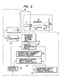
- the ink drop writing apparatus has an electromechanical transducer or a piezo-oscillator 10 connected to the high frequency electric power source 12 and a nozzle 14 attached with the piezo-oscillator 10.
- pressurized ink 16 is injected as an ink column 18 to pass through a charging electrode 20 disposed in front of the nozzle 14.
- deflection plates 22, 24 Disposed in front of the charging electrode 20 are deflection plates 22, 24 which is connected with a high voltage source 26.
- a writing medium 28 or paper, and a gutter 30 are arranged in front of the deflection plates 22, 24.
- the piezo-oscillator 10 and the charging electrode 20 are connected to the character signal generator 32 and according to the character signals, writing dots 34 are formed on the paper 28.
- the character pattern 36 is produced.
- the above ink drop writing apparatus operates as follows:
- an address determining circuit 46 Connected to an amplifier 40 of the pattern signal generator 32 through a D/A converter and an ink drop charging voltage setting ROM44 is an address determining circuit 46 which is connected to a pattern register 48, an uncharged dummy drop location storage register 50, and a top/bottom uncharged dummy drop number storage register 52. To each registers 50 and 52 are input the signals from the uncharged dummy drop location calculating circuit 54.
- FIG.3 For example, in the 32 X 32 dot matrix character shown in Fig.3, eight uncharged ummy drops are allotted for each column.
- Figure 4(a) shows the matrix elements of one column in the 32 X 32 dot matrix. A single writing ink drop is allotted to each element. The character pattern is formed when the writing ink drops adhere to the paper 28 to form the writing dots 34 at such locations, shown shaded, as are necessary to produce the character pattern.
- the eight uncharged dummy drops allotted to this column are produced as follows.
- the marks shown at the left of the character formation ink drop column indicate the locations at which the uncharged dummy drops can be produced. These marked locations are scanned from the top where the deflection is greatest to the bottom and the uncharged dummy drops are produced at both ends of the chain of marked points.
- the dummy drops are generated at locations numbered 1 through 6. When the scanning reaches the bottom of the column, it returns to the top to further determine the uncharged dummy drops generating locations out of the remaining candidate locations in such a way that the dummy dot locations are always at both ends of the chain of the remaining candidate locations.
- the pattern register 48 stores the binary signals shown in Figure 5(a). This pattern signal is processed in the uncharged dummy drop generation location calculating circuit 54 and the calculation result is stored in the uncharged dummy drop generating location storage register 50.
- the content to be stored in the register 50 is as shown in Figure 5(b).
- the values of the top/bottom uncharged dummy drop number storage register 52 are zero.
- the address determining circuit 46 Based on the contents of Figure 5(a) and 5(b) as well as the value of the top/bottom uncharged dummy dot number storage register 52, the address determining circuit 46 generates the address data shown in Figure 6(a). That is, the data of address 0 is produced as many times as the number of the bottom uncharged dummy drops (in this case there is no such data generated). Then the data of the pattern register 48 (the data of Figure 5(a)) is read out from LSB to MSB .
- the data of address 0 When there is a 0 bit the data of address 0 is generated, and when there is a bit 1, the data of the uncharged dummy drop generation location storage register corresponding to that bit position (i.e., the data of Figure 5(b)) is checked. If this data is found to be 0, the data corresponding to that bit position is output as the address data. When 1, the data 0 is generated as the address data of the uncharged dummy drop, followed by the outputting of the data corresponding to that bit position. Finally, the data of address 0 is generated as many times as the number of the uncharged top dummy drops (in this case there is no such data generated), i.e., 40 address data in total.
- the ROM 44 stores the binary signal for each address representing the drop charging voltage level, as shown in Figure 7.
- the D/A converter 42 outputs the level signal of Figure 6(b) as the character signal.
- the character signal generated by the character signal generation circuit 32 as described above is supplied to the ink jet writing unit to print characters with little distortion.
- the uncharged dummy drops are generated where the interference between the character pattern formation drops is great and the recording distortion is most likely to occur. This widens the distance between the character formation drops at locations where the interference between the drops is great, thus reducing the interference and effectively preventing the occurrence of the recording distortion.
- the method of this invention of preventing the recording distortion by producing the uncharged dummy drops may be combined with the conventional method of using as the writing drops the ink drops which are produced n drops apart. This combination makes it possible to reduce the value of n, thus preventing the reduction in the recording speed.
Landscapes
- Particle Formation And Scattering Control In Inkjet Printers (AREA)
Abstract
Description
- This invention relates to an ink drop writing apparatus and more particularly to an improved ink drop writing apparatus free from the print distortion.
- Apparatus has been developed for printing on a writing medium of the information represented by video signals by generating a stream of ink drops, directing these ink drops toward the writing medium, and then, deflecting the ink drops in response to the video signal, in a manner so that when the ink drops reach the writing medium, they provide a representation of the information contained in the video signals . The general apparatus employed for producing the ink drops consists of an ink reservoir in which there is ink under pressure. The ink reservoir feeds a pipe which is connected to a nozzle .
- An electromechanical transducer is employed to vibrate the pipe and the nozzle at some suitable high frequency which causes the ink to be injected from the nozzle in a stream which shortly thereafter breaks into individual drops.
- In the region just before the stream breaks into drops there is placed a charging tunnel through which the stream is projected, which serves the function of applying video signals to the individual drops . Downstream of the tunnel there is provided a pair of deflection plates which have a fixed potential thereacross. The electric field which is created between the plates acts on the charged drops causing them to be deflected in an amount determined by the amplitude of the charge on the drops. Downstream of the deflection plates is usually a nozzle or through for catching any drops which do not have any charge and transferring them to a waste reservoir. There is also positioned the writing medium which is to receive the deflected ink drops, which thereby form the images representative of the video signals. The writing medium is usually moved in synchronism with the application of video signals to the drops .
- In the printing apparatus of the type briefly discribed above, when the writing ink drops are continuously used as the pattern formation ink drops, the ink drops are not able to be given a desired amount of charge and deflection and therefore form writing dots on positions deviated from the correct positions. As a result, the writing deformation occurs . The cause of the deformation is an electrostatic and aerodynamic interference between the pattern formation ink drops .
- In the conventional apparatus as shown in U.S. Patent'No. 3,562,757 issued to Bischoff on Feb. 9, 1971, every Nth dops (N is a natural number) injected from the nozzle are used as the writing ink drops and the remaining drops produced between the writing ink drops are not charged. No charge dropsare discarded as dummy or guard drops to broaden the gap between the character pattern formation ink drops so as to reduce the interference therebetween. This apparatus, however, has the drawback that the writing speed of characters is greatly reduced to 1/n+1 of the former speed.
- An object of the present invention is to provide an improved ink dop writing apparatus.
- Another object of the present invention is to provide a novel ink drop writing apparatus which prevent the writing distortion without reducing the writing speed.
- According to the present invention, predetermined number of uncharged dummy ink drops are produced only between the character pattern formation drops for each column.
-
- Figs . 1 and 2 are a schematic arrangement and a block diagram showing the preferred embodiment of the present invention.
- Fig. 3 is a pattern of writing character explaining the operation of the apparatus of Fig. 1 and 2.
- Fig. 4 is a character pattern to explain the insertion of the uncharged dummy ink drops .
- Fig. 5 shows binary signals converted from the character pattern of Fig. 4.
- Fig. 6 is a table explaning the operation of D/A converter.
- Fig. 7 is a table showing the relation between address and voltage level, and Fig. 8 is a graph showing the relation between address and voltage level.
- In Fig. 1 and 2, the ink drop writing apparatus has an electromechanical transducer or a piezo-
oscillator 10 connected to the high frequencyelectric power source 12 and anozzle 14 attached with the piezo-oscillator 10. When the piezo-oscillator 10 is applied with high frequency wave, pressurizedink 16 is injected as anink column 18 to pass through acharging electrode 20 disposed in front of thenozzle 14. - Disposed in front of the
charging electrode 20 aredeflection plates high voltage source 26. Awriting medium 28 or paper, and agutter 30 are arranged in front of thedeflection plates oscillator 10 and thecharging electrode 20 are connected to thecharacter signal generator 32 and according to the character signals, writingdots 34 are formed on thepaper 28. Thus thecharacter pattern 36 is produced. - The above ink drop writing apparatus operates as follows:
- (1) The voltage from the high
frequency power source 12 is applied to the piezo-oscillator 10 to excite thenozzle 14, and the pressurizedink 16 is supplied to thenozzle 14 from which the ink is injected to continuously produce uniform ink drops 38 at the same frequency as the highfrequency power source 12. - (2) Desired number of drops are used as writing ink drops to form the characters . When these writing ink drops 38 separate from the
ink column 18, the character signal voltage from thecharacter signal generator 32 is applied to thecharging electrode 20 for charging the writing ink drops in proportion to the applied voltage . - (3) The charged writing ink drops are passed through the electrostatic field formed by applying the voltage from the
high voltage source 26 to thedeflecting plates writing dots 34 on thepaper 28 as shown in Fig. 3. - (4) The above drop formation, charging and deflecting actions are performed while the
paper 28 is moved in the second direction Y penpenducular to the first direction X. Consequently, thecharacter pattern 36 are performed. - (5) Ink drops 39 that were not used for the formation of
charactor pattern 36 are permitted to pass straight on to thegutter 30 where they are recorded for reuse. - Connected to an
amplifier 40 of thepattern signal generator 32 through a D/A converter and an ink drop charging voltage setting ROM44 is anaddress determining circuit 46 which is connected to apattern register 48, an uncharged dummy droplocation storage register 50, and a top/bottom uncharged dummy dropnumber storage register 52. To eachregisters location calculating circuit 54. - For example, in the 32
X 32 dot matrix character shown in Fig.3, eight uncharged ummy drops are allotted for each column. Figure 4(a) shows the matrix elements of one column in the 32X 32 dot matrix. A single writing ink drop is allotted to each element. The character pattern is formed when the writing ink drops adhere to thepaper 28 to form thewriting dots 34 at such locations, shown shaded, as are necessary to produce the character pattern. - In this case, the eight uncharged dummy drops allotted to this column are produced as follows. The marks shown at the left of the character formation ink drop column indicate the locations at which the uncharged dummy drops can be produced. These marked locations are scanned from the top where the deflection is greatest to the bottom and the uncharged dummy drops are produced at both ends of the chain of marked points. In this example, the dummy drops are generated at locations numbered 1 through 6. When the scanning reaches the bottom of the column, it returns to the top to further determine the uncharged dummy drops generating locations out of the remaining candidate locations in such a way that the dummy dot locations are always at both ends of the chain of the remaining candidate locations. This process is repeated until the number of the uncharged dummy dots reaches eight. In this example, this process ends when the locations numbered 7 and 8 in the Figure 4(a) are determined. In the case of Figure 4(b) mere the number of uncharged dummy drop generation candidate locations is less than eight, the remaining dummy dot locations will be positioned at the top, bottom, top, bottom, ... in that order. The drops generated at the top of the column are called top uncharged dummy drops and those generated at the bottom are called uncharged bottom dummy drops.
- For the pattern shown in Figure 4(a), the
pattern register 48 stores the binary signals shown in Figure 5(a). This pattern signal is processed in the uncharged dummy drop generationlocation calculating circuit 54 and the calculation result is stored in the uncharged dummy drop generatinglocation storage register 50. The content to be stored in theregister 50 is as shown in Figure 5(b). - In this example, the values of the top/bottom uncharged dummy drop
number storage register 52 are zero. Based on the contents of Figure 5(a) and 5(b) as well as the value of the top/bottom uncharged dummy dotnumber storage register 52, theaddress determining circuit 46 generates the address data shown in Figure 6(a). That is, the data ofaddress 0 is produced as many times as the number of the bottom uncharged dummy drops (in this case there is no such data generated). Then the data of the pattern register 48 (the data of Figure 5(a)) is read out from LSB to MSB . When there is a 0 bit the data ofaddress 0 is generated, and when there is abit 1, the data of the uncharged dummy drop generation location storage register corresponding to that bit position (i.e., the data of Figure 5(b)) is checked. If this data is found to be 0, the data corresponding to that bit position is output as the address data. When 1, thedata 0 is generated as the address data of the uncharged dummy drop, followed by the outputting of the data corresponding to that bit position. Finally, the data ofaddress 0 is generated as many times as the number of the uncharged top dummy drops (in this case there is no such data generated), i.e., 40 address data in total. - The
ROM 44 stores the binary signal for each address representing the drop charging voltage level, as shown in Figure 7. Thus, from the address data shown in Figure 6(a), the D/A converter 42 outputs the level signal of Figure 6(b) as the character signal. The character signal generated by the charactersignal generation circuit 32 as described above is supplied to the ink jet writing unit to print characters with little distortion. - Therefore, with the above embodiment of the present invention, the uncharged dummy drops are generated where the interference between the character pattern formation drops is great and the recording distortion is most likely to occur. This widens the distance between the character formation drops at locations where the interference between the drops is great, thus reducing the interference and effectively preventing the occurrence of the recording distortion.
- The method of this invention of preventing the recording distortion by producing the uncharged dummy drops may be combined with the conventional method of using as the writing drops the ink drops which are produced n drops apart. This combination makes it possible to reduce the value of n, thus preventing the reduction in the recording speed.
- As can be seen from the foregoing, with this invention it is possible to prevent the occurrence of writing distortion without greatly reducing the writing speed.
Claims (2)
Applications Claiming Priority (2)
| Application Number | Priority Date | Filing Date | Title |
|---|---|---|---|
| JP178977/80 | 1980-12-19 | ||
| JP55178977A JPS57103852A (en) | 1980-12-19 | 1980-12-19 | Ink jet recorder |
Publications (3)
| Publication Number | Publication Date |
|---|---|
| EP0054921A2 true EP0054921A2 (en) | 1982-06-30 |
| EP0054921A3 EP0054921A3 (en) | 1983-08-31 |
| EP0054921B1 EP0054921B1 (en) | 1986-07-30 |
Family
ID=16057954
Family Applications (1)
| Application Number | Title | Priority Date | Filing Date |
|---|---|---|---|
| EP81110546A Expired EP0054921B1 (en) | 1980-12-19 | 1981-12-17 | Method for reducing print distortion of ink drop writing apparatus |
Country Status (4)
| Country | Link |
|---|---|
| US (1) | US4430656A (en) |
| EP (1) | EP0054921B1 (en) |
| JP (1) | JPS57103852A (en) |
| DE (1) | DE3175050D1 (en) |
Cited By (1)
| Publication number | Priority date | Publication date | Assignee | Title |
|---|---|---|---|---|
| WO1993010977A1 (en) * | 1991-11-29 | 1993-06-10 | Domino Printing Sciences Plc | Continuous ink jet printing |
Families Citing this family (4)
| Publication number | Priority date | Publication date | Assignee | Title |
|---|---|---|---|---|
| US6879969B2 (en) * | 2001-01-21 | 2005-04-12 | Volvo Technological Development Corporation | System and method for real-time recognition of driving patterns |
| JP2012162036A (en) * | 2011-02-08 | 2012-08-30 | Hitachi Industrial Equipment Systems Co Ltd | Inkjet recording apparatus |
| JP7199109B1 (en) * | 2021-06-23 | 2023-01-05 | 紀州技研工業株式会社 | Correction Method of Print Distortion in Inkjet Printer |
| JP7274770B2 (en) * | 2021-06-28 | 2023-05-17 | 紀州技研工業株式会社 | inkjet printer |
Citations (2)
| Publication number | Priority date | Publication date | Assignee | Title |
|---|---|---|---|---|
| US3562757A (en) * | 1968-02-28 | 1971-02-09 | Dick Co Ab | Guard drop technique for ink jet systems |
| US4086601A (en) * | 1976-03-30 | 1978-04-25 | International Business Machines Corporation | Sequential ink jet printing system with variable number of guard drops |
-
1980
- 1980-12-19 JP JP55178977A patent/JPS57103852A/en active Granted
-
1981
- 1981-12-17 DE DE8181110546T patent/DE3175050D1/en not_active Expired
- 1981-12-17 EP EP81110546A patent/EP0054921B1/en not_active Expired
- 1981-12-18 US US06/332,248 patent/US4430656A/en not_active Expired - Lifetime
Patent Citations (2)
| Publication number | Priority date | Publication date | Assignee | Title |
|---|---|---|---|---|
| US3562757A (en) * | 1968-02-28 | 1971-02-09 | Dick Co Ab | Guard drop technique for ink jet systems |
| US4086601A (en) * | 1976-03-30 | 1978-04-25 | International Business Machines Corporation | Sequential ink jet printing system with variable number of guard drops |
Cited By (1)
| Publication number | Priority date | Publication date | Assignee | Title |
|---|---|---|---|---|
| WO1993010977A1 (en) * | 1991-11-29 | 1993-06-10 | Domino Printing Sciences Plc | Continuous ink jet printing |
Also Published As
| Publication number | Publication date |
|---|---|
| EP0054921A3 (en) | 1983-08-31 |
| EP0054921B1 (en) | 1986-07-30 |
| DE3175050D1 (en) | 1986-09-04 |
| JPS6230110B2 (en) | 1987-06-30 |
| JPS57103852A (en) | 1982-06-28 |
| US4430656A (en) | 1984-02-07 |
Similar Documents
| Publication | Publication Date | Title |
|---|---|---|
| US4490729A (en) | Ink jet printer | |
| US4050077A (en) | Liquid droplet supplying system | |
| US3828354A (en) | Ink drop charge compensation method and apparatus for ink drop printer | |
| US3813676A (en) | Non-sequential symbol generation system for fluid jet printer | |
| US3846800A (en) | Ink jet recording method and apparatus | |
| US3769631A (en) | Increasing throughput in ink jet printing by drop skipping and reducing ink jet merging and splatter using a stairstep generator | |
| US4032924A (en) | Distortion reduction in ink jet system printer | |
| EP0054921A2 (en) | Method for reducing print distortion of ink drop writing apparatus | |
| US4180225A (en) | Ink jet recording apparatus | |
| US4302761A (en) | Ink jet system printer of the charge amplitude controlling type capable of printing different size characters | |
| US4472722A (en) | Ink jet printing method | |
| US4849909A (en) | Ink-jet recording device | |
| US4424518A (en) | Column dot formation in an ink jet system printer of the charge amplitude controlling type | |
| US4438440A (en) | Print-distortion compensating device for the ink jet printing apparatus | |
| US3875574A (en) | Method for improving performance of an ink jet bar code printer | |
| US4354195A (en) | Ink jet recording apparatus | |
| US4633268A (en) | Ink jet printer | |
| JP2621489B2 (en) | Charge control method of ink droplet in charge control type ink jet printer | |
| JPS5843027B2 (en) | Inkjet recording device | |
| JP2727867B2 (en) | Inkjet printer distortion correction device | |
| JPS5847992B2 (en) | inkjet plotter | |
| JPH06115077A (en) | Print distortion correcting device of ink jet printer | |
| JPS591596B2 (en) | Inkjet recording device | |
| KR820000702B1 (en) | Picture-information display system | |
| JPS5848353B2 (en) | inkjet plotter |
Legal Events
| Date | Code | Title | Description |
|---|---|---|---|
| PUAI | Public reference made under article 153(3) epc to a published international application that has entered the european phase |
Free format text: ORIGINAL CODE: 0009012 |
|
| AK | Designated contracting states |
Designated state(s): DE IT |
|
| PUAL | Search report despatched |
Free format text: ORIGINAL CODE: 0009013 |
|
| AK | Designated contracting states |
Designated state(s): DE IT |
|
| 17P | Request for examination filed |
Effective date: 19830809 |
|
| GRAA | (expected) grant |
Free format text: ORIGINAL CODE: 0009210 |
|
| AK | Designated contracting states |
Kind code of ref document: B1 Designated state(s): DE IT |
|
| REF | Corresponds to: |
Ref document number: 3175050 Country of ref document: DE Date of ref document: 19860904 |
|
| ITF | It: translation for a ep patent filed |
Owner name: MODIANO & ASSOCIATI S.R.L. |
|
| PLBE | No opposition filed within time limit |
Free format text: ORIGINAL CODE: 0009261 |
|
| STAA | Information on the status of an ep patent application or granted ep patent |
Free format text: STATUS: NO OPPOSITION FILED WITHIN TIME LIMIT |
|
| 26N | No opposition filed | ||
| ITTA | It: last paid annual fee | ||
| PGFP | Annual fee paid to national office [announced via postgrant information from national office to epo] |
Ref country code: DE Payment date: 19980227 Year of fee payment: 17 |
|
| PG25 | Lapsed in a contracting state [announced via postgrant information from national office to epo] |
Ref country code: DE Free format text: LAPSE BECAUSE OF NON-PAYMENT OF DUE FEES Effective date: 19991001 |