EP0054776B1 - Compliance steer control system - Google Patents
Compliance steer control system Download PDFInfo
- Publication number
- EP0054776B1 EP0054776B1 EP81110090A EP81110090A EP0054776B1 EP 0054776 B1 EP0054776 B1 EP 0054776B1 EP 81110090 A EP81110090 A EP 81110090A EP 81110090 A EP81110090 A EP 81110090A EP 0054776 B1 EP0054776 B1 EP 0054776B1
- Authority
- EP
- European Patent Office
- Prior art keywords
- vehicle
- elastomeric
- steering
- wheels
- suspension
- Prior art date
- Legal status (The legal status is an assumption and is not a legal conclusion. Google has not performed a legal analysis and makes no representation as to the accuracy of the status listed.)
- Expired
Links
- 239000000725 suspension Substances 0.000 claims description 32
- 239000012212 insulator Substances 0.000 claims description 31
- 230000000694 effects Effects 0.000 claims description 13
- 239000012530 fluid Substances 0.000 claims description 6
- 210000002445 nipple Anatomy 0.000 claims description 6
- 230000008901 benefit Effects 0.000 description 3
- 210000000988 bone and bone Anatomy 0.000 description 2
- 230000035939 shock Effects 0.000 description 2
- TVEXGJYMHHTVKP-UHFFFAOYSA-N 6-oxabicyclo[3.2.1]oct-3-en-7-one Chemical compound C1C2C(=O)OC1C=CC2 TVEXGJYMHHTVKP-UHFFFAOYSA-N 0.000 description 1
- 238000003754 machining Methods 0.000 description 1
- 230000002093 peripheral effect Effects 0.000 description 1
Images





Classifications
-
- B—PERFORMING OPERATIONS; TRANSPORTING
- B60—VEHICLES IN GENERAL
- B60G—VEHICLE SUSPENSION ARRANGEMENTS
- B60G99/00—Subject matter not provided for in other groups of this subclass
-
- B—PERFORMING OPERATIONS; TRANSPORTING
- B60—VEHICLES IN GENERAL
- B60G—VEHICLE SUSPENSION ARRANGEMENTS
- B60G3/00—Resilient suspensions for a single wheel
- B60G3/18—Resilient suspensions for a single wheel with two or more pivoted arms, e.g. parallelogram
- B60G3/20—Resilient suspensions for a single wheel with two or more pivoted arms, e.g. parallelogram all arms being rigid
- B60G3/22—Resilient suspensions for a single wheel with two or more pivoted arms, e.g. parallelogram all arms being rigid a rigid arm forming the axle housing
- B60G3/225—Resilient suspensions for a single wheel with two or more pivoted arms, e.g. parallelogram all arms being rigid a rigid arm forming the axle housing the arm being of the trailing wishbone type
-
- B—PERFORMING OPERATIONS; TRANSPORTING
- B60—VEHICLES IN GENERAL
- B60G—VEHICLE SUSPENSION ARRANGEMENTS
- B60G7/00—Pivoted suspension arms; Accessories thereof
- B60G7/006—Attaching arms to sprung or unsprung part of vehicle, characterised by comprising attachment means controlled by an external actuator, e.g. a fluid or electrical motor
-
- B—PERFORMING OPERATIONS; TRANSPORTING
- B62—LAND VEHICLES FOR TRAVELLING OTHERWISE THAN ON RAILS
- B62D—MOTOR VEHICLES; TRAILERS
- B62D7/00—Steering linkage; Stub axles or their mountings
- B62D7/06—Steering linkage; Stub axles or their mountings for individually-pivoted wheels, e.g. on king-pins
- B62D7/14—Steering linkage; Stub axles or their mountings for individually-pivoted wheels, e.g. on king-pins the pivotal axes being situated in more than one plane transverse to the longitudinal centre line of the vehicle, e.g. all-wheel steering
- B62D7/146—Steering linkage; Stub axles or their mountings for individually-pivoted wheels, e.g. on king-pins the pivotal axes being situated in more than one plane transverse to the longitudinal centre line of the vehicle, e.g. all-wheel steering characterised by comprising means for steering by acting on the suspension system, e.g. on the mountings of the suspension arms
-
- B—PERFORMING OPERATIONS; TRANSPORTING
- B60—VEHICLES IN GENERAL
- B60G—VEHICLE SUSPENSION ARRANGEMENTS
- B60G2200/00—Indexing codes relating to suspension types
- B60G2200/10—Independent suspensions
-
- B—PERFORMING OPERATIONS; TRANSPORTING
- B60—VEHICLES IN GENERAL
- B60G—VEHICLE SUSPENSION ARRANGEMENTS
- B60G2200/00—Indexing codes relating to suspension types
- B60G2200/10—Independent suspensions
- B60G2200/13—Independent suspensions with longitudinal arms only
- B60G2200/132—Independent suspensions with longitudinal arms only with a single trailing arm
-
- B—PERFORMING OPERATIONS; TRANSPORTING
- B60—VEHICLES IN GENERAL
- B60G—VEHICLE SUSPENSION ARRANGEMENTS
- B60G2200/00—Indexing codes relating to suspension types
- B60G2200/40—Indexing codes relating to the wheels in the suspensions
- B60G2200/462—Toe-in/out
-
- B—PERFORMING OPERATIONS; TRANSPORTING
- B60—VEHICLES IN GENERAL
- B60G—VEHICLE SUSPENSION ARRANGEMENTS
- B60G2202/00—Indexing codes relating to the type of spring, damper or actuator
- B60G2202/40—Type of actuator
- B60G2202/41—Fluid actuator
- B60G2202/413—Hydraulic actuator
-
- B—PERFORMING OPERATIONS; TRANSPORTING
- B60—VEHICLES IN GENERAL
- B60G—VEHICLE SUSPENSION ARRANGEMENTS
- B60G2204/00—Indexing codes related to suspensions per se or to auxiliary parts
- B60G2204/10—Mounting of suspension elements
- B60G2204/14—Mounting of suspension arms
-
- B—PERFORMING OPERATIONS; TRANSPORTING
- B60—VEHICLES IN GENERAL
- B60G—VEHICLE SUSPENSION ARRANGEMENTS
- B60G2204/00—Indexing codes related to suspensions per se or to auxiliary parts
- B60G2204/10—Mounting of suspension elements
- B60G2204/15—Mounting of subframes
-
- B—PERFORMING OPERATIONS; TRANSPORTING
- B60—VEHICLES IN GENERAL
- B60G—VEHICLE SUSPENSION ARRANGEMENTS
- B60G2204/00—Indexing codes related to suspensions per se or to auxiliary parts
- B60G2204/62—Adjustable continuously, e.g. during driving
-
- B—PERFORMING OPERATIONS; TRANSPORTING
- B60—VEHICLES IN GENERAL
- B60G—VEHICLE SUSPENSION ARRANGEMENTS
- B60G2206/00—Indexing codes related to the manufacturing of suspensions: constructional features, the materials used, procedures or tools
- B60G2206/01—Constructional features of suspension elements, e.g. arms, dampers, springs
- B60G2206/60—Subframe construction
Definitions
- the present invention relates to a compliance steer control system for a vehicle having steerable front wheels mounted to said vehicle through a front suspension arrangement, a power steering system associated with said front wheels through a linkage arrangement, which power steering includes a source of hydraulic pressure, a hydraulic servo having first and second chambers, a control valve responsive to the rotation of a steering wheel of the vehicle for selectively pressurizing said first and second chambers, and rear wheels mounted to said vehicle by a rear suspension arrangement which includes elastomeric mounting members.
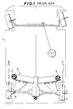
- Fig. 1 of the drawings shows a vehicle 1, which, by way of example only, is equipped with a conventional semi-trailing arm suspension system 2.
- a conventional semi-trailing arm suspension system 2 With this arrangement when the vehicle traverses a corner at high speed the elastomeric insulators 3 via which the suspension 2 is connected to the vehicle chassis 4 are distorted via a side force F as shown, causing the orientation or alignment of the rear wheels 5 to vary by an angle "E".
- this so called “compliance steer” phenomenon has persisted and deteriorates vehicle handling especially during high speed cornering.
- a system is provided responsive to the pressurization of said first and second chambers for producing a bias which tends to compensate for, or accentuate the compliance steering effect caused by said elastomeric mounting members by varying the steering angle of said front and/or rear wheels with respect to the steering angles said front and/or rear wheels would otherwise assume with respect to said vehicle during cornering or like.
- the invention features an arrangement wherein a power steering is integrated with expandible hydraulic devices which vary the angle that either the front or rear wheels would otherwise assume during cornering so as to either compensate for, or accentuate the so called “compliance steering effect" induced in the rear suspension so as to improve the handling of the vehicle.
- the expandible hydraulic devices are disposed with the rear suspension they are adapted to, for high speed cornering correction, bias the rear suspension mounting insulators in a manner which either neutralizes the distortion thereof by the side force (produced when the vehicle traverses a corner) or reverse same so as to maintain the rear wheels either in their normal position or bias them slightly beyond same to assume an angle the reverse of which would occur due to the "compliance steer" effect.
- the arrangement is such that the angle through which the front wheels are intentionally turned by the driver is increased to, prior to the actual generation of the side force, induce a situation wherein the compliance steering effect will be increased. This quite unexpectedly improves the handling of the vehicle in a manner similar to the correction (or over correction) of the compliance steering of the rear suspension.
- a further feature of the invention comes in sensing the vehicle speed and operating the compliance steering control arrangement incorporated with the rear suspension at low speed, so as to increase the "compliance steering" effect and reduce the turning circle of the vehicle.
- a further feature of the invention is deemed to come in the use of especially chambered elastomeric insulator units which both simplify and lighten the system as a whole as well as prevent any rattling and undue vibration.
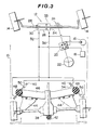
- the numeral 10 indicates a vehicle equipped with a power steering 12 which is associated with the front wheels 14.
- This power steering includes a pump 16 and a reservoir 18.
- a control valve 20 of the power steering is fluidly communicated with the pump 16 and responsive to the rotation of a steering wheel 22 which is, as shown, mechanically connected to a rack and pinion steering gear 24.
- a hydraulic servo 26 is operatively connected to a tie rod 28 and fluidly connected to the control valve 20 in a manner such that when the steering wheel 22 is rotated anti-clockwise, a chamber 30 of the servo 26 is pressurized with hydraulic fluid from the pump 16 through a conduit 32.
- the vehicle 10 is in this case, merely by way of example, a front engine - rear wheel drive type wherein the final drive or differential gear 38 is mounted to the vehicle chassis 40 through an elastomeric insulator 42.
- the rear suspension is, by way of example, a semi-trailing arm type wherein pivotal trailing arms 44 are pivotally mounted on a sub-frame 46. This sub-frame is in turn mounted to the vehicle through elastomeric insulators 48.
- extendible shock absorber-like cylinders 50-56 Connected between the vehicle chassis 40 and the elastomeric insulators 48 are extendible shock absorber-like cylinders 50-56. These hydraulic cylinders are connected to the control valve 20 so that upon the steering wheel 22 being rotated in the anti-clockwise direction the cylinders 50 and 56 are pressurized through conduit 32 while cylinders 52 and 54 are drained via conduit 36 to bias the sub-frame 46 to rotate in a manner as shown in Fig. 3 (viz., rotate anti-clockwise as seen in the figure). Conversely, when the steering wheel is rotated in the clockwise direction the hydraulic cylinders 52 and 54 are pressurized while cylinders 50 and 56 are drained to cause the sub-frame to rotate in the reverse direction (viz., clockwise).
- the pressure fed to the hydraulic cylinders is varied in accordance with the sharpness of the turn of the vehicle and tends to vary with the magnitude of side force subsequently produced. That is to say, if the vehicle is driven through a sharp corner at high speed, a relatively high side force is apt to be produced, however, as the output of the control valve is relatively high under such conditions the compliance steer phenomenon is compensated for without the need of additional pressure control valves or the like.
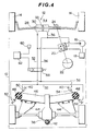
- Fig. 4 shows a second embodiment of the present invention.
- This embodiment is essentially the same as the previous one except for the additional provision of a solenoid controlled valve 58 which is interposed in the hydraulic conduits 32, 36 interconnecting the control valve 20 and the hydraulic cylinders.
- This valve is operatively connected to a speed sensor 60 (such as the vehicle speedometer or the like) via a suitable comparison and amplifying circuit 62, so that at low speeds the connection between conduits 32 and 36 may be reversed to reverse the action of the hydraulic cylinders 50-56.
- a speed sensor 60 such as the vehicle speedometer or the like
- the hydraulic cylinders may be employed to actually induce or amplify the compliance steer effect in the rear suspension to reduce the turning circle of the vehicle, while at speeds above a predetermined level the connection is rendered the same as in the case of the first embodiment to produce exactly the same effect.
- Fig. 5 of the drawings shows a third embodiment of the present invention.
- the hydraulic cylinders of the first and second embodiments are replaced with chambered elastomeric insulator units 64 such as shown in Figs. 6 to 11.
- chambered elastomeric insulator units 64 such as shown in Figs. 6 to 11.
- Figs. 6 and 7 one example of a chambered elastomeric mounting unit 64 is shown.
- an elastomeric insulator body or bush 66 is encased in two semi-cylindrical casing members 68 which are vulcanized or otherwise fixedly secured to the outer periphery thereof.
- Recesses 70 formed in the insulator are closed off by the casing members to define closed variable volume chambers 72.
- the casing members are suitably apertured and have connection nipples 74 or the like welded or otherwise connected to the outer periphery of the casing members 68.
- the above described unit is disposed within a suitable collar 76 ( Figures 8 and 9) fixed to the suspension sub-frame 46.
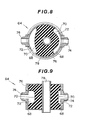
- Figs. 8 and 9 show the above described chambered insulator unit disposed in a collar 76 and with one of the chambers pressurized.
- the sleeve 78 through which a bolt or the like is disposed to fasten the suspension sub-frame 46 to the vehicle chassis 40, is displaced from its normal or home position.
- the non-pressurized chamber is, as shown reduced in capacity under this condition, the fluid contained therein being in part pumped back through the conduiting to the control valve 20 and reservoir 18.
- the dimensions of the recesses 70 formed in the elastomeric bushes of course should be selected in a manner that the upon the pressurization the force which biases the sleeve 78 from its home position is at least equal to or greater than the side force produced. This selection of course requires the output pressure of the control valve 20 to be known along with the elastic modulus of the insulator bush, the surface area of the recesses which will produce a laterally acting force etc; all of which are apt to vary from vehicle to vehicle.
- Figs. 10 and 11 show a second example of the chambered elastomeric insulator unit 64'.
- the connection nipples 74 are disposed through apertures formed in the semi-cylindrical casing members 68 so as project into the variable volume chambers 72 per se.
- This arrangement has the benefit in that as the nipples 74 do not project from the casing members the resulting flush outer peripheral surface allows for the chambered insulator units 64' to be placed in a collar of the type normally used to secure a normal non-chambered elastomeric insulator.
- the conduits 32, 36 may be connected to the nipples 74 through apertures which may be readily drilled or otherwise formed in the existing sub-frame collars 76. This of course allows for existing suspension units to have the invention applied thereto without major redesign and machining.
- the use of the chambered elastomeric insulator units also has the advantages that, vibration is not transmitted to the chassis 40 as is possible in the case that metallic extensible struts or cylinders are used, the arrangement as a whole is highly compact and special mounting sites on the vehicle chassis for the cylinders are not required.
- Fig. 12 shows a fourth embodiment of the present invention.
- the invention is applied to the front wheels of the vehicle as distinct from the rear wheels as in the previous embodiments.
- a hydraulic servo 79 disposed between the front wheels 14 includes a piston 84 which divides the servo interior into first and second variable volume chambers 80, 82.
- Pins 88 which pivotally connect traverse links 89 of a strut and traverse link type front suspension to the vehicle are interconnected with the piston 84 via connecting rods 86.
- Each of these pins 88 are mounted to the chassis 40 of the vehicle through elastomeric insulators or bushes 90 which function to damp vibration and shock from the front wheels 14.
- the servo 79 in this case, is connected to the control valve 20 through conduits 92, 94 which respectively communicate with chambers 82, 80.
- chamber 82 of the servo 78 and the chamber 30 of the power steering servo 26 are pressurized through conduit 92 while chambers 80 and 34 are drained via conduit 94.
- the piston 33 and the tie rod 28 are moved axially to the right (as seen in the drawing) to cause the front wheels 14 to turn to the left via the mechanical connection provided therebetween by the knuckle rods 95.
- the piston 84 is driven to the left (as seen in the drawing) to move the pin 88 which pivotally mounts the front left-hand wheel traverse link 89 in the outboard direction via the connection provided by the connection rods 86 and pull the pin 88 associated with the front right-hand wheel traverse link inboard.
- the result is that the ball joint or king pin 96 of the front left-hand wheel is moved outwardly by a small amount while the corresponding ball joint 96 of the front right-hand wheel is moved inboard by the same distance.
- the tie rod 28 accordingly tends to pull and push the respective knuckle rods 96 of the front left and right hand wheels to induce the front wheels to turn through an additional angle to the left and increase the angle through which the front wheels are turned by a degree slightly greater than that intentionally induced by the driver.
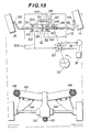
- Fig. 13 shows a fifth embodiment of the present invention. This embodiment like the last is applied to the front wheels 14 of the vehicle. However, unlike the previous embodiments the system of the invention does not act through the suspension of the vehicle but through the power steering 26 per se.
- a servo 98 is connected to a movable housing 100 which houses the servo 26 and rack and pinion gear 24 therein and which is in turn is connected to the chassis 40 of the vehicle through elastomeric bushes or insulators 102.
- a chamber 104 of the servo 98 is pressurized through conduit 106 to bias the piston 108 of the servo to the right (as seen in the drawings) while the piston 33 of the power steering servo 26 is also biased in the same direction via the pressurization of chamber 30 thereof.
- a chamber 110 of the servo 98 is pressurized via conduit 112.
- Simultaneously chamber 34 of the power steeer- ing servo 26 is pressurized moving the piston 33 to the left.
- the degree of movement of the housing is of course controllable by selecting the size and elastomeric modulus of the bushes 102 which mount the housing 100 to the chassis 40 and which are distorted upon movement of the housing 100 under the influence of the servo 98. Other factors influencing the movement are, the diameter of the piston and the output pressure of the control valve 20.
- the bushes 102 may be chambered and suitably connected to the control valve 20 if so desired in place of the piston type servo.
Landscapes
- Engineering & Computer Science (AREA)
- Mechanical Engineering (AREA)
- Chemical & Material Sciences (AREA)
- Combustion & Propulsion (AREA)
- Transportation (AREA)
- Vehicle Body Suspensions (AREA)
Description
- The present invention relates to a compliance steer control system for a vehicle having steerable front wheels mounted to said vehicle through a front suspension arrangement, a power steering system associated with said front wheels through a linkage arrangement, which power steering includes a source of hydraulic pressure, a hydraulic servo having first and second chambers, a control valve responsive to the rotation of a steering wheel of the vehicle for selectively pressurizing said first and second chambers, and rear wheels mounted to said vehicle by a rear suspension arrangement which includes elastomeric mounting members.
- Fig. 1 of the drawings shows a vehicle 1, which, by way of example only, is equipped with a conventional semi-trailing
arm suspension system 2. With this arrangement when the vehicle traverses a corner at high speed theelastomeric insulators 3 via which thesuspension 2 is connected to the vehicle chassis 4 are distorted via a side force F as shown, causing the orientation or alignment of therear wheels 5 to vary by an angle "E". Despite various advances in suspension design this so called "compliance steer" phenomenon has persisted and deteriorates vehicle handling especially during high speed cornering. - It is known e.g. from US-A-2 998 263, DE-A-1 630 630 and CH-A-368 063 to vary the orientation of the wheels of a vehicle with respect to the body of the vehicle in response to pressurisation of first and second chambers of a hydraulic servo of a power steering system to alter the inclination of the wheels relative to the vehicle in a transverse vertical plane. However, no means is provided to overcome the above compliance steering problem, i.e. the steering effect of the rear wheels of a vehicle by varying the inclination thereof relative to a longitudinal vertical plane when cornering.
- It is an object of the invention to provide means to compensate for, or accentuate the above compliance steering effect.
- According to the invention, a system is provided responsive to the pressurization of said first and second chambers for producing a bias which tends to compensate for, or accentuate the compliance steering effect caused by said elastomeric mounting members by varying the steering angle of said front and/or rear wheels with respect to the steering angles said front and/or rear wheels would otherwise assume with respect to said vehicle during cornering or like.
- The invention features an arrangement wherein a power steering is integrated with expandible hydraulic devices which vary the angle that either the front or rear wheels would otherwise assume during cornering so as to either compensate for, or accentuate the so called "compliance steering effect" induced in the rear suspension so as to improve the handling of the vehicle.
- In the case that the expandible hydraulic devices are disposed with the rear suspension they are adapted to, for high speed cornering correction, bias the rear suspension mounting insulators in a manner which either neutralizes the distortion thereof by the side force (produced when the vehicle traverses a corner) or reverse same so as to maintain the rear wheels either in their normal position or bias them slightly beyond same to assume an angle the reverse of which would occur due to the "compliance steer" effect.
- In the case where the expandible hydraulic devices are used in conjunction with the front wheels, the arrangement is such that the angle through which the front wheels are intentionally turned by the driver is increased to, prior to the actual generation of the side force, induce a situation wherein the compliance steering effect will be increased. This quite unexpectedly improves the handling of the vehicle in a manner similar to the correction (or over correction) of the compliance steering of the rear suspension.
- A further feature of the invention comes in sensing the vehicle speed and operating the compliance steering control arrangement incorporated with the rear suspension at low speed, so as to increase the "compliance steering" effect and reduce the turning circle of the vehicle.
- A further feature of the invention is deemed to come in the use of especially chambered elastomeric insulator units which both simplify and lighten the system as a whole as well as prevent any rattling and undue vibration.
- The features and advantages of the arrangement of the present invention will become more clearly appreciated from the following description taken in conjunction with the accompanying drawings in which
- Fig. 1 is a schematic plan view of a vehicle having a prior art rear suspension subject to compliance steering;
- Fig. 2 is a schematic plan view of a vehicle equipped with a first embodiment of the present invention;
- Fig. 3 is a plan view similar to that of Fig. 2 but showing the rear suspension being biased to "over correct" for the compliance steering effect;
- Fig. 4 is a plan view similar to that of Figs. 2 and 3 showing a third embodiment of the present invention wherein a solenoid controlled reversal valve is incorporated into the system to induce increased compliance steering at low speeds and reduce the turning circle of the vehicle;
- Fig. 5 shows a third embodiment of the present invention wherein the elastomeric bodies or bushes of the mounting insulators of the rear suspension are chambered to form a vital part of the system according to the invention;
- Figs. 6 and 7 are respectively partly sectioned plan and elevations of a chambered elastomeric insulator unit such as used in Fig. 5;
- Figs. 8 and 9 are fully sectioned plan and elevations of the chambered elastomeric insulator unit shown in Figs. 6 and 7 showing one of the chambers thereof pressurized;
- Figs. 10 and 11 shown a variation of the chambered elastomeric insulator unit shown in Figs. 8 and 9;
- Fig. 12 is a schematic plan view of a fourth embodiment of the present invention wherein the invention is applied to the front wheels of the vehicle; and
- Fig. 13 is a schematic plan view of a vehicle equipped with a fifth embodiment of the present invention which is also applied to the front wheels of the vehicle;
- Turning now to the Figures and more specifically to Figs. 2 and 3 of the drawings wherein a first embodiment of the present invention is shown, the
numeral 10 indicates a vehicle equipped with apower steering 12 which is associated with thefront wheels 14. This power steering includes apump 16 and areservoir 18. Acontrol valve 20 of the power steering is fluidly communicated with thepump 16 and responsive to the rotation of asteering wheel 22 which is, as shown, mechanically connected to a rack andpinion steering gear 24. Ahydraulic servo 26 is operatively connected to atie rod 28 and fluidly connected to thecontrol valve 20 in a manner such that when thesteering wheel 22 is rotated anti-clockwise, achamber 30 of theservo 26 is pressurized with hydraulic fluid from thepump 16 through aconduit 32. This drives apiston 33 of thepower steering servo 26 to the right as seen in the drawings to assist the steering of the front wheels. Conversely, when the steering wheel is rotated in the clockwise direction achamber 34 of theservo 26 is pressurized viaconduit 36 and thepiston 33 is driven to stroke to the left (as seen in the drawings) to assist the turning of the wheels to the right. - The above kind of arrangement is of course well known, examples of such being found in USP 4,290,452 issued on September 22, 1981 in the name of Takahashi et al and USP 4,137,989 issued on February 6, 1979 in the name of Rehfeld.
- The
vehicle 10 is in this case, merely by way of example, a front engine - rear wheel drive type wherein the final drive ordifferential gear 38 is mounted to thevehicle chassis 40 through anelastomeric insulator 42. In this vehicle the rear suspension is, by way of example, a semi-trailing arm type wherein pivotal trailingarms 44 are pivotally mounted on asub-frame 46. This sub-frame is in turn mounted to the vehicle throughelastomeric insulators 48. - Connected between the
vehicle chassis 40 and theelastomeric insulators 48 are extendible shock absorber-like cylinders 50-56. These hydraulic cylinders are connected to thecontrol valve 20 so that upon thesteering wheel 22 being rotated in the anti-clockwise direction thecylinders conduit 32 whilecylinders conduit 36 to bias thesub-frame 46 to rotate in a manner as shown in Fig. 3 (viz., rotate anti-clockwise as seen in the figure). Conversely, when the steering wheel is rotated in the clockwise direction thehydraulic cylinders cylinders - With this arrangement, when the
front wheels 14 are turned so as to induce the vehicle to turn to the left (for example) and traverse an arcuate path, the side force F which is accordingly produced is balanced by the bias applied to thesub-frame 46 of the rear suspension by the hydraulic cylinders, with the result that the rear wheels do not undergo the compliance steering phenomenon. - As the pressure outputted from the
control valve 20 varies with such parameters as the degree by which the steering wheel is turned, the pressure fed to the hydraulic cylinders is varied in accordance with the sharpness of the turn of the vehicle and tends to vary with the magnitude of side force subsequently produced. That is to say, if the vehicle is driven through a sharp corner at high speed, a relatively high side force is apt to be produced, however, as the output of the control valve is relatively high under such conditions the compliance steer phenomenon is compensated for without the need of additional pressure control valves or the like. - It is also possible to "over-correct" the compliance steering effect by selecting, by way of example, the diameter of the hydraulic cylinders 50-56 and accordingly the surface area on which the pressure from the
control valve 20 acts. Thus, if so desired it can be arranged that the rear suspension be biased beyond its normal position against the side force F to actually assume an orientation such as shown in Fig. 3 during cornering. - Fig. 4 shows a second embodiment of the present invention. This embodiment is essentially the same as the previous one except for the additional provision of a solenoid controlled
valve 58 which is interposed in thehydraulic conduits control valve 20 and the hydraulic cylinders. This valve is operatively connected to a speed sensor 60 (such as the vehicle speedometer or the like) via a suitable comparison and amplifyingcircuit 62, so that at low speeds the connection betweenconduits - Fig. 5 of the drawings shows a third embodiment of the present invention. In this case the hydraulic cylinders of the first and second embodiments are replaced with chambered
elastomeric insulator units 64 such as shown in Figs. 6 to 11. In Figs. 6 and 7 one example of a chamberedelastomeric mounting unit 64 is shown. In this arrangement, an elastomeric insulator body orbush 66 is encased in twosemi-cylindrical casing members 68 which are vulcanized or otherwise fixedly secured to the outer periphery thereof.Recesses 70 formed in the insulator are closed off by the casing members to define closedvariable volume chambers 72. The casing members are suitably apertured and haveconnection nipples 74 or the like welded or otherwise connected to the outer periphery of thecasing members 68. - The above described unit is disposed within a suitable collar 76 (Figures 8 and 9) fixed to the
suspension sub-frame 46. - With this arrangement, the need for two separate hydraulic cylinders per insulator is eliminated by orienting the chambers as shown in Fig. 5. That is to say, in a manner which enables the application of the maximum torque to the
sub-frame 46 upon pressurization of one of the twovariable volume chambers 72. - Figs. 8 and 9, show the above described chambered insulator unit disposed in a
collar 76 and with one of the chambers pressurized. As shown, thesleeve 78 through which a bolt or the like is disposed to fasten thesuspension sub-frame 46 to thevehicle chassis 40, is displaced from its normal or home position. The non-pressurized chamber is, as shown reduced in capacity under this condition, the fluid contained therein being in part pumped back through the conduiting to thecontrol valve 20 andreservoir 18. The dimensions of therecesses 70 formed in the elastomeric bushes of course should be selected in a manner that the upon the pressurization the force which biases thesleeve 78 from its home position is at least equal to or greater than the side force produced. This selection of course requires the output pressure of thecontrol valve 20 to be known along with the elastic modulus of the insulator bush, the surface area of the recesses which will produce a laterally acting force etc; all of which are apt to vary from vehicle to vehicle. - Figs. 10 and 11 show a second example of the chambered elastomeric insulator unit 64'. In this case, the
connection nipples 74 are disposed through apertures formed in thesemi-cylindrical casing members 68 so as project into thevariable volume chambers 72 per se. This arrangement of course has the benefit in that as thenipples 74 do not project from the casing members the resulting flush outer peripheral surface allows for the chambered insulator units 64' to be placed in a collar of the type normally used to secure a normal non-chambered elastomeric insulator. Theconduits nipples 74 through apertures which may be readily drilled or otherwise formed in the existingsub-frame collars 76. This of course allows for existing suspension units to have the invention applied thereto without major redesign and machining. - The use of the chambered elastomeric insulator units also has the advantages that, vibration is not transmitted to the
chassis 40 as is possible in the case that metallic extensible struts or cylinders are used, the arrangement as a whole is highly compact and special mounting sites on the vehicle chassis for the cylinders are not required. - Fig. 12 shows a fourth embodiment of the present invention. In this embodiment the invention is applied to the front wheels of the vehicle as distinct from the rear wheels as in the previous embodiments.
- In this embodiment, a
hydraulic servo 79 disposed between thefront wheels 14 includes apiston 84 which divides the servo interior into first and secondvariable volume chambers Pins 88 which pivotally connecttraverse links 89 of a strut and traverse link type front suspension to the vehicle are interconnected with thepiston 84 via connectingrods 86. Each of thesepins 88 are mounted to thechassis 40 of the vehicle through elastomeric insulators orbushes 90 which function to damp vibration and shock from thefront wheels 14. Theservo 79, in this case, is connected to thecontrol valve 20 throughconduits chambers steering wheel 22 is rotated in the anti-clockwise direction for example,chamber 82 of theservo 78 and thechamber 30 of thepower steering servo 26 are pressurized throughconduit 92 whilechambers conduit 94. Thus, thepiston 33 and thetie rod 28 are moved axially to the right (as seen in the drawing) to cause thefront wheels 14 to turn to the left via the mechanical connection provided therebetween by theknuckle rods 95. Simultaneously, thepiston 84 is driven to the left (as seen in the drawing) to move thepin 88 which pivotally mounts the front left-handwheel traverse link 89 in the outboard direction via the connection provided by theconnection rods 86 and pull thepin 88 associated with the front right-hand wheel traverse link inboard. The result is that the ball joint orking pin 96 of the front left-hand wheel is moved outwardly by a small amount while the corresponding ball joint 96 of the front right-hand wheel is moved inboard by the same distance. Thetie rod 28 accordingly tends to pull and push therespective knuckle rods 96 of the front left and right hand wheels to induce the front wheels to turn through an additional angle to the left and increase the angle through which the front wheels are turned by a degree slightly greater than that intentionally induced by the driver. - In the case that a "double wish bone" type suspension is employed with the front wheels as different from the above described "transverse link-strut" type, then it would be necessary to connect the
piston 84 to the pins on which both of the upper and lower control arms are pivoted. This could be simply achieved by using two sets of connection rods or even using chambered insulator units such as shown in Figs. 10 and 11 for example in place of the insulators or bushes 90 (in the case of a "strut-transverse link" type suspension) and/or their equivalents in the case of a "double wish bone" suspension. - Fig. 13 shows a fifth embodiment of the present invention. This embodiment like the last is applied to the
front wheels 14 of the vehicle. However, unlike the previous embodiments the system of the invention does not act through the suspension of the vehicle but through thepower steering 26 per se. In this arrangement aservo 98 is connected to amovable housing 100 which houses theservo 26 and rack andpinion gear 24 therein and which is in turn is connected to thechassis 40 of the vehicle through elastomeric bushes orinsulators 102. With this arrangement when thesteering wheel 22 is rotated in the anti-clockwise direction for example, achamber 104 of theservo 98 is pressurized throughconduit 106 to bias thepiston 108 of the servo to the right (as seen in the drawings) while thepiston 33 of thepower steering servo 26 is also biased in the same direction via the pressurization ofchamber 30 thereof. Conversely, when thesteering wheel 22 is rotated in the clock-wise direction achamber 110 of theservo 98 is pressurized viaconduit 112. Simultaneouslychamber 34 of the power steeer-ing servo 26 is pressurized moving thepiston 33 to the left. With this arrangement for any given amount of intentional steering, thefront wheels 14 are turned through an additional amount because of the movement of thehousing 100. The degree of movement of the housing is of course controllable by selecting the size and elastomeric modulus of thebushes 102 which mount thehousing 100 to thechassis 40 and which are distorted upon movement of thehousing 100 under the influence of theservo 98. Other factors influencing the movement are, the diameter of the piston and the output pressure of thecontrol valve 20. Alternatively, thebushes 102, may be chambered and suitably connected to thecontrol valve 20 if so desired in place of the piston type servo.
Claims (10)
Applications Claiming Priority (4)
| Application Number | Priority Date | Filing Date | Title |
|---|---|---|---|
| JP17606080U JPS5798909U (en) | 1980-12-10 | 1980-12-10 | |
| JP176060/80U | 1980-12-10 | ||
| JP17386780A JPS5799470A (en) | 1980-12-11 | 1980-12-11 | Apparatus for controlling compliance steerage |
| JP173867/80 | 1980-12-11 |
Publications (2)
| Publication Number | Publication Date |
|---|---|
| EP0054776A1 EP0054776A1 (en) | 1982-06-30 |
| EP0054776B1 true EP0054776B1 (en) | 1985-09-04 |
Family
ID=26495677
Family Applications (1)
| Application Number | Title | Priority Date | Filing Date |
|---|---|---|---|
| EP81110090A Expired EP0054776B1 (en) | 1980-12-10 | 1981-12-02 | Compliance steer control system |
Country Status (3)
| Country | Link |
|---|---|
| US (1) | US4440254A (en) |
| EP (1) | EP0054776B1 (en) |
| DE (1) | DE3172164D1 (en) |
Families Citing this family (40)
| Publication number | Priority date | Publication date | Assignee | Title |
|---|---|---|---|---|
| JPS58164477A (en) * | 1982-03-24 | 1983-09-29 | Nissan Motor Co Ltd | Rear-wheel steering controller |
| JPS58214470A (en) * | 1982-06-07 | 1983-12-13 | Nissan Motor Co Ltd | Rear wheel steering device |
| JPS58214457A (en) * | 1982-06-07 | 1983-12-13 | Nissan Motor Co Ltd | Front wheel auxiliary steering device |
| JPS58214469A (en) * | 1982-06-07 | 1983-12-13 | Nissan Motor Co Ltd | Rear wheel steering device |
| US4579186A (en) * | 1983-10-15 | 1986-04-01 | Nissan Motor Co., Ltd. | Vehicle steering system |
| US4586581A (en) * | 1983-10-15 | 1986-05-06 | Nissan Motor Co., Ltd. | Vehicle control system |
| US4588039A (en) * | 1983-10-17 | 1986-05-13 | Nissan Motor Co., Ltd. | Vehicle steering control system and method of operating same |
| JPS6092979A (en) * | 1983-10-27 | 1985-05-24 | Nissan Motor Co Ltd | Rear-wheel steering apparatus |
| JPS6072769U (en) * | 1983-10-27 | 1985-05-22 | 日産自動車株式会社 | Vehicle pressure fluid control device |
| JPS60161259A (en) * | 1984-01-31 | 1985-08-22 | Nissan Motor Co Ltd | Vehicle rear wheel steering device |
| JPS60161265A (en) * | 1984-01-31 | 1985-08-22 | Nissan Motor Co Ltd | Steering for car |
| US4572316A (en) * | 1984-03-15 | 1986-02-25 | Mazda Motor Corporation | Four-wheel steering system for vehicle |
| JPS6127770A (en) * | 1984-07-17 | 1986-02-07 | Nissan Motor Co Ltd | Rear-wheel steering gear |
| US4616846A (en) * | 1984-08-14 | 1986-10-14 | Honda Giken Kogyo Kabushiki Kaisha | Control device for a suspension |
| US4706989A (en) * | 1985-06-12 | 1987-11-17 | Nissan Motor Co., Ltd. | Rear independent suspension for automotive vehicle |
| EP0217360B1 (en) * | 1985-10-01 | 1990-01-31 | Toyota Jidosha Kabushiki Kaisha | Suspension control system |
| GB8529601D0 (en) * | 1985-12-02 | 1986-01-08 | Lotus Group Plc | Vehicle with front & rear wheel steering |
| FR2596010B1 (en) * | 1986-03-18 | 1988-07-01 | Peugeot | REAR AXLE WITH ACTIVE MICRO-STEERING FOR MOTOR VEHICLE |
| JP2532079B2 (en) * | 1987-01-30 | 1996-09-11 | 日産自動車株式会社 | Rotary control valve for power steering |
| DE3802905A1 (en) * | 1987-01-30 | 1988-08-11 | Nissan Motor | HYDRAULIC FLUID PRESSURE CONTROL SYSTEM FOR USE WITH A POWER STEERING STEERING |
| US4826184A (en) * | 1987-04-06 | 1989-05-02 | Kuehmchel Blaine G | Snowmobile power steering system |
| JPH0825470B2 (en) * | 1987-05-20 | 1996-03-13 | 日産自動車株式会社 | Rear wheel rudder angle control method |
| JPH0818571B2 (en) * | 1987-06-29 | 1996-02-28 | 日産自動車株式会社 | Power steering hydraulic control device |
| FR2617930B1 (en) * | 1987-07-07 | 1992-07-31 | Peugeot | HYDROELASTIC SUPPORT, IN PARTICULAR FOR PROVIDING THE SUSPENSION OF AN ENGINE IN A VEHICLE |
| FR2628496B1 (en) * | 1988-03-08 | 1990-12-21 | Peugeot | ELASTIC CONNECTION WITH HYDRAULIC RIGIDIFICATION |
| FR2628493B1 (en) * | 1988-03-08 | 1990-12-21 | Peugeot | ELASTIC ARTICULATION WITH HYDRAULIC RIGIDIFICATION |
| US5313389A (en) * | 1988-09-13 | 1994-05-17 | Aisin Seiki Kabushiki Kaisha | Fail-safe mechanism for vehicle stability augmentation steering system |
| US5141069A (en) * | 1988-09-13 | 1992-08-25 | Aisin Seiki Kabushiki Kaisha | Steering mechanism with toe-in control |
| US5156229A (en) * | 1988-09-13 | 1992-10-20 | Aisin Seiki Kabushiki Kaisha | Steering control apparatus |
| FR2651737B1 (en) * | 1989-09-12 | 1991-12-27 | Peugeot | REAR STEERING CONTROL DEVICE FOR MOTOR VEHICLE WITH FOUR STEERING WHEELS. |
| JP3211434B2 (en) * | 1991-12-18 | 2001-09-25 | アイシン精機株式会社 | Vehicle guidance control device |
| US5413319A (en) * | 1994-08-10 | 1995-05-09 | Gencorp Inc. | Fluid damped bushing |
| US5496018A (en) * | 1994-08-10 | 1996-03-05 | Gencorp Inc. | Fluid damped bushing with encapsulated window metal |
| KR19980031242A (en) * | 1996-10-31 | 1998-07-25 | 오상수 | Hydraulic Bush Control System for Vehicle Suspension |
| US6272409B1 (en) * | 1998-09-24 | 2001-08-07 | Dana Corporation | Motor vehicle steering box with Ackerman control |
| DE10329037A1 (en) * | 2003-06-27 | 2005-01-13 | Audi Ag | Method and device for vibration damping |
| FR2900622B1 (en) * | 2006-05-05 | 2008-08-15 | Andre Rey | MOTOR VEHICLE WITH DIRECTION A CREMAILLERE |
| DE102014003506A1 (en) * | 2014-03-14 | 2015-09-17 | Carl Freudenberg Kg | Hydraulic bushing assembly |
| CN109177671B (en) * | 2018-10-22 | 2021-01-15 | 北京长城华冠汽车技术开发有限公司 | Manufacturing method of multi-link type rear suspension, multi-link type rear suspension and vehicle |
| CN113074202A (en) * | 2020-01-06 | 2021-07-06 | 北汽福田汽车股份有限公司 | Bushing assembly, control device and control strategy thereof and vehicle |
Family Cites Families (13)
| Publication number | Priority date | Publication date | Assignee | Title |
|---|---|---|---|---|
| FR1059319A (en) * | 1952-06-30 | 1954-03-24 | Steering device for motor vehicles | |
| US2804311A (en) * | 1954-03-05 | 1957-08-27 | Clifford L Pobanz | Hydraulic anti-roll stabilizer system |
| US2757938A (en) * | 1954-04-09 | 1956-08-07 | Charles W Crowder | Hydraulic motor vehicle stabilizer |
| US2893751A (en) * | 1954-12-27 | 1959-07-07 | Gen Motors Corp | Vehicle anti-roll device and power steering control therefor |
| FR1151546A (en) * | 1955-06-24 | 1958-01-31 | Ajax Engineering Corp | Distribution of metal under pressure |
| FR1260219A (en) * | 1960-03-26 | 1961-05-05 | Transmission device | |
| CH368063A (en) * | 1961-05-02 | 1963-03-15 | Zimmermann Gaston | Method for stabilizing a motor vehicle and device for implementing this method |
| DE1630639A1 (en) * | 1967-10-07 | 1971-06-09 | Albert Knoeller | Additional device for the carriage suspension |
| US3768827A (en) * | 1971-12-27 | 1973-10-30 | A Hickman | Self-steering standem axle suspension |
| US3836134A (en) * | 1973-03-19 | 1974-09-17 | Wright Barry Corp | Pneumatic isolator |
| US4137989A (en) * | 1977-10-11 | 1979-02-06 | General Motors Corporation | Rotary hydraulic servo for steering gear |
| JPS5522572A (en) * | 1978-08-07 | 1980-02-18 | Nissan Motor Co Ltd | Rotary valve |
| JPS55147968A (en) * | 1979-05-02 | 1980-11-18 | Ricoh Co Ltd | Linear pulse motor |
-
1981
- 1981-11-09 US US06/319,282 patent/US4440254A/en not_active Expired - Lifetime
- 1981-12-02 DE DE8181110090T patent/DE3172164D1/en not_active Expired
- 1981-12-02 EP EP81110090A patent/EP0054776B1/en not_active Expired
Also Published As
| Publication number | Publication date |
|---|---|
| EP0054776A1 (en) | 1982-06-30 |
| DE3172164D1 (en) | 1985-10-10 |
| US4440254A (en) | 1984-04-03 |
Similar Documents
| Publication | Publication Date | Title |
|---|---|---|
| US4440254A (en) | Compliance steer control system | |
| EP0096345B1 (en) | Compliance steer control arrangement for automotive vehicle suspension | |
| US4706989A (en) | Rear independent suspension for automotive vehicle | |
| JP2863923B2 (en) | Rear wheel suspension system for rear wheel steering vehicles | |
| US5700025A (en) | Vehicle suspension system for a steerable wheel | |
| US4519627A (en) | Automative compliance steering control supension | |
| EP0154991B1 (en) | Four-wheel steering system for vehicle | |
| US5292149A (en) | Arrangement for the active adjustment of a motor vehicle wheel | |
| EP0150858B1 (en) | Four-wheel steering control system for vehicle | |
| US3601426A (en) | Vehicle rear assembly | |
| US4545602A (en) | Independent rear suspension system for automotive vehicle | |
| JP2863922B2 (en) | Rear wheel suspension system for rear wheel steering vehicles | |
| US5435407A (en) | Hydrostatic manual vehicle steering system | |
| US5080185A (en) | Rear suspension system for four-wheel-steered vehicle | |
| US4640379A (en) | Vehicle steering control system | |
| JPH0345409A (en) | Trailing type rear suspension | |
| US3649042A (en) | Vehicle suspension having automatic corrective steering | |
| US5286048A (en) | Suspension system for dirigible rear wheels | |
| JPS5970258A (en) | Auxiliary steering device of rear wheel | |
| US3063731A (en) | Hydraulic steering system | |
| JPH03276804A (en) | Rear wheel suspension device for rear wheel-steered vehicle | |
| JPS6328709A (en) | Stabilizer device | |
| JPS60161258A (en) | Auxiliary steering apparatus for car | |
| JPS6322712A (en) | Suspension device for vehicle | |
| JPH02144203A (en) | Rear wheel suspension device for rear wheel steering vehicle |
Legal Events
| Date | Code | Title | Description |
|---|---|---|---|
| PUAI | Public reference made under article 153(3) epc to a published international application that has entered the european phase |
Free format text: ORIGINAL CODE: 0009012 |
|
| AK | Designated contracting states |
Designated state(s): DE FR GB |
|
| 17P | Request for examination filed |
Effective date: 19820624 |
|
| RAP1 | Party data changed (applicant data changed or rights of an application transferred) |
Owner name: NISSAN MOTOR CO., LTD. |
|
| GRAA | (expected) grant |
Free format text: ORIGINAL CODE: 0009210 |
|
| AK | Designated contracting states |
Designated state(s): DE FR GB |
|
| REF | Corresponds to: |
Ref document number: 3172164 Country of ref document: DE Date of ref document: 19851010 |
|
| ET | Fr: translation filed | ||
| PLBE | No opposition filed within time limit |
Free format text: ORIGINAL CODE: 0009261 |
|
| STAA | Information on the status of an ep patent application or granted ep patent |
Free format text: STATUS: NO OPPOSITION FILED WITHIN TIME LIMIT |
|
| 26N | No opposition filed | ||
| PGFP | Annual fee paid to national office [announced via postgrant information from national office to epo] |
Ref country code: GB Payment date: 19981204 Year of fee payment: 18 |
|
| PGFP | Annual fee paid to national office [announced via postgrant information from national office to epo] |
Ref country code: FR Payment date: 19981209 Year of fee payment: 18 |
|
| PGFP | Annual fee paid to national office [announced via postgrant information from national office to epo] |
Ref country code: DE Payment date: 19981214 Year of fee payment: 18 |
|
| PG25 | Lapsed in a contracting state [announced via postgrant information from national office to epo] |
Ref country code: GB Free format text: LAPSE BECAUSE OF NON-PAYMENT OF DUE FEES Effective date: 19991202 |
|
| GBPC | Gb: european patent ceased through non-payment of renewal fee |
Effective date: 19991202 |
|
| PG25 | Lapsed in a contracting state [announced via postgrant information from national office to epo] |
Ref country code: FR Free format text: LAPSE BECAUSE OF NON-PAYMENT OF DUE FEES Effective date: 20000831 |
|
| PG25 | Lapsed in a contracting state [announced via postgrant information from national office to epo] |
Ref country code: DE Free format text: LAPSE BECAUSE OF NON-PAYMENT OF DUE FEES Effective date: 20001003 |
|
| REG | Reference to a national code |
Ref country code: FR Ref legal event code: ST |