EP0054639B1 - Imaging element for an electrophotographic machine - Google Patents
Imaging element for an electrophotographic machine Download PDFInfo
- Publication number
- EP0054639B1 EP0054639B1 EP81108128A EP81108128A EP0054639B1 EP 0054639 B1 EP0054639 B1 EP 0054639B1 EP 81108128 A EP81108128 A EP 81108128A EP 81108128 A EP81108128 A EP 81108128A EP 0054639 B1 EP0054639 B1 EP 0054639B1
- Authority
- EP
- European Patent Office
- Prior art keywords
- drum
- photoconductor
- bar
- sleeve
- imaging element
- Prior art date
- Legal status (The legal status is an assumption and is not a legal conclusion. Google has not performed a legal analysis and makes no representation as to the accuracy of the status listed.)
- Expired
Links
- 238000003384 imaging method Methods 0.000 title claims description 11
- 238000003780 insertion Methods 0.000 claims description 4
- 230000037431 insertion Effects 0.000 claims description 4
- 239000004020 conductor Substances 0.000 claims description 3
- 229910052782 aluminium Inorganic materials 0.000 description 14
- XAGFODPZIPBFFR-UHFFFAOYSA-N aluminium Chemical compound [Al] XAGFODPZIPBFFR-UHFFFAOYSA-N 0.000 description 14
- 238000000034 method Methods 0.000 description 7
- 230000009471 action Effects 0.000 description 4
- 230000008901 benefit Effects 0.000 description 4
- 238000004519 manufacturing process Methods 0.000 description 3
- 230000001681 protective effect Effects 0.000 description 3
- 229920002799 BoPET Polymers 0.000 description 2
- 239000005041 Mylar™ Substances 0.000 description 2
- XLOMVQKBTHCTTD-UHFFFAOYSA-N Zinc monoxide Chemical compound [Zn]=O XLOMVQKBTHCTTD-UHFFFAOYSA-N 0.000 description 2
- 239000011248 coating agent Substances 0.000 description 2
- 238000000576 coating method Methods 0.000 description 2
- 239000000463 material Substances 0.000 description 2
- 230000007246 mechanism Effects 0.000 description 2
- 239000002390 adhesive tape Substances 0.000 description 1
- 239000004411 aluminium Substances 0.000 description 1
- 239000011324 bead Substances 0.000 description 1
- 230000005540 biological transmission Effects 0.000 description 1
- 238000004140 cleaning Methods 0.000 description 1
- 238000010073 coating (rubber) Methods 0.000 description 1
- -1 i.e. Substances 0.000 description 1
- 229910052751 metal Inorganic materials 0.000 description 1
- 239000002184 metal Substances 0.000 description 1
- 239000002245 particle Substances 0.000 description 1
- 239000002985 plastic film Substances 0.000 description 1
- 229920006255 plastic film Polymers 0.000 description 1
- 230000008569 process Effects 0.000 description 1
- 230000009467 reduction Effects 0.000 description 1
- 230000004044 response Effects 0.000 description 1
- 230000000717 retained effect Effects 0.000 description 1
- 239000011787 zinc oxide Substances 0.000 description 1
Images

Classifications
-
- G—PHYSICS
- G03—PHOTOGRAPHY; CINEMATOGRAPHY; ANALOGOUS TECHNIQUES USING WAVES OTHER THAN OPTICAL WAVES; ELECTROGRAPHY; HOLOGRAPHY
- G03G—ELECTROGRAPHY; ELECTROPHOTOGRAPHY; MAGNETOGRAPHY
- G03G15/00—Apparatus for electrographic processes using a charge pattern
- G03G15/75—Details relating to xerographic drum, band or plate, e.g. replacing, testing
- G03G15/751—Details relating to xerographic drum, band or plate, e.g. replacing, testing relating to drum
- G03G15/752—Details relating to xerographic drum, band or plate, e.g. replacing, testing relating to drum with renewable photoconductive layer
Definitions
- This invention relates to imaging elements for electrophotographic machines.
- a photoconductor element in sheet form is wound around a rotatable drum. Often, the sheet is wrapped around the drum using a clamping device, also known as a tensioning device.
- a clamping device also known as a tensioning device.
- Such photoconductor sheets can be used and reused in an electrophotographic machine many times to make prints or copies.
- this type of photoconductor offers advantages of both lower initial machine cost and lower subsequent photoconductor replacement cost, and is therefore preferred over prior art arrangements such as incrementally moveable photoconductor rolls or the coating-on-drum type design having an aluminum drum on which a photosensitive coating is directly applied.
- the low cost photoconductor sheet generally requires replacement more often as compared to some prior art designs because of the shorter life span of a photosensitive composition used in such low cost photoconductor sheets.
- Photoconductor sheets incorporated in modern low cost copiers or printers therefore do not remain in service indefinitely. Instead, they must be replaced periodically. Typically, such a photoconductor sheet is replaced at the usage rate of about every 10,000 or more copies. Moreover, the useful life of a photoconductor may be cut short substantially because of physical damage to the photoconductor sheet due to foreign objects, and mishandling during the clearance of a paper jam performed either by an operator or a service person.
- the replacement of a used or damaged photoconductor typically involves an unfastening and removal of the used or damaged photoconductor from the electrophotographic drum, and a disconnection of any associated wiring or electrical contact to the photoconductor itself.
- a new photoconductor is then removed from its protective jacket, and properly fastened onto the electrophotographic drum.
- the required associated wiring or electrical contact to the photoconductor must also be restored.
- the above-described photoconductor replacement procedure typically involves, in addition, an alignment of the photoconductor to the electrophotographic drum as well as handling of loose machine parts which could be inadvertently misplaced. Such replacement task may appear to be or is actually too complex to an untrained operator. Furthermore, once the new photoconductor is removed from its protective jacket, some such photoconductors can not be exposed to an average lighted room for more than 5 to 10 minutes without suffering partial or permanent damage. Hence, there is an additional requirement that the photoconductor replacement be completed quickly to avoid any potential damage to the new photoconductor itself. The latter requirement tends to add pressure and further complicates the replacement procedure. For these reasons, most photoconductor replacements, heretofore, have been performed by trained service personnel..
- U.S. Patent Specification No. 2,085,093 discloses a sheet holding means for a picture transmission system.
- a cylinder is provided with a groove into which projects a series of pins adapted to enagage a series of apertures in one end of a sheet.
- a bar is provided on one face with a series of pins which engages apertures in the other end of the sheet. After the pins of the bar engage the apertures, the bar is forced into the groove and locked in place to apply an even tension to the sheet and hold it in contact with the surface of the cylinder.
- the bar may be pivoted at one end and latched at the other so as to hold the bar in the groove of the cylinder.
- the bar is coated with rubber or other frictional material, and is provided along its lower edge with notches to accommodate the pins carried by the cylinder.
- only one end of the sheet is provided with apertures to engage the pins of the cylinder. The sheet is forced into good contact with the surface of the cylinder by the frictional engagement of the rubber coating with the other end of the sheet.
- a prior photoconductor drum seal for a copier is disclosed by L.C. Brown, et al, in an article entitled "Drum Seal Interlock", pages 3837-38, Vol. 20, No. 10, March 1978, IBM Technical Disclosure Bulletin.
- a drum having a groove is configured to receive a wrap-around photoconductor sheet. The ends of the photoconductor sheets are retained internally to the drum by a sealed bar.
- An interlock switch is provided to ensure proper placement of the sealed bar in the groove of the drum so as to avoid machine damage.
- a prior photoconductor clamping device or tensioning device for a copier is disclosed in U.S. Patent Specification No. 3,834,808.
- the apparatus in that specification comprises a cylindrical drum having a portion of its surface cut away to provide an axially extending notched portion in the surface of the drum, and clamping means provided in the notched portion.
- the clamping means includes a first holding means for holding one end of a photosensitive sheet, and a second holding means having an elastic member connected between the drum and the other end of the photosensitive sheet for resiliently holding the photosensitive sheet on the drum.
- the disclosed device includes a drum having a recess, a front end clamp member in the recess for clamping the leading end portion of a photoconductor sheet and a back end clamp member for clamping the trailing end portion of the photoconductor sheet.
- U.S. Patent Specification No. 3536397 shows an imaging element with a replaceable flexible photoconductor sleeve releasably mounted about the periphery of the drum.
- the sleeve When on the drum, the sleeve is tensioned at its ends either by flaired portions at the ends of the drum or by 0-rings mounted at these ends.
- the sleeve when tensioned does not closely fit round the drum, but is spaced therefrom between the end portions.
- an imaging element for an electrophotographic machine comprising a rotatable drum carrying a replaceable flexible sleeve conductor element, comprising a backing layer an electrically conductive layer and a photoconductive layer, round its periphery, and a tensioning bar arranged for insertion into a channel in the drum surface parallel to the drum axis, characterised in that said tensioning bar carries conductive resilient means along its length which, upon insertion of the bar into the channel, engage a strip of the sleeve having no photoconductive layer to tension the sleeve against the drum and make electrical contact with the electrically conductive layer.
- the developed image is then removed from the photoconductor image area to a copy sheet at transfer station 16 for subsequent fixing.
- the image area may be subjected to cleaning at station 15, as the drum 10 rotates in the clockwise direction at a constant speed.
- Sheets of paper are supplied, one sheet at a time, from bin 20. These sheets of paper follow path 21, including passing through hot fusing rolls 22, to reach exit pocket 23.
- Copier 1 may employ a flexible photoconductor 12 of the type having a form of closed loop sleeve.
- this type of photoconductor is inherently simpler and less expensive to manufacture than the prior coating-on-drum type photoconductor design having an aluminum drum and on which a photosensitive coating is directly applied.
- this flexible photoconductor sleeve design also has a cost advantage over incrementally moveable photoconductor rolls. More specifically, the cost of an automatically incremented photoconductor roll system may well approximate the manufacturing cost of an entire low-cost copier. For these reasons, this type of photoconductor offers advantages of both lower initial machine cost and lower subsequent photoconductor replacement cost to a customer.
- photoconductor sleeve 12 has a plastic film backing 122, which is sold commonly under the trademark Mylar, and is formed from a photoconductor sheet by bonding its two ends using adhesive tape 128.
- a layer of aluminum 124 is deposited on the Mylar backing 122 to form an ground plane.
- a photosensitive layer 126 such as zinc oxide, is then deposited on top of aluminum layer 124 on the outside surface of photoconductor sleeve 12.
- a strip of photoconductor on area 125 along the length of photoconductor sleeve 12 is removed exposing the aluminum ground plane 124.
- drum 10 is a specially designed device having thereon a unique photoconductor sleeve tensioning feature.
- the drum 10 has a channel 102 on the cylindrical drum periphery thereof, running substantially parallel to the drum central axis 104, along the length of the drum 10.
- An elongated bar 106 having a cross sectional configuration for fitting within the channel 102, may be pivotally mounted at one of its ends at an internal point 108 on drum 10.
- a latching hook 101 may also be provided at the other end of bar 106.
- a spring 103 is positioned on bar 106 to tension photoconductor sleeve 12 in response to forcing the sleeve 12 partially into the channel 102 by the bar 106.
- the spring 103 is an elongated structure having a substantially S-shaped cross section along the channel 102.
- Elongated spring 103 may also contain slots 105 along its length so as to provide greater flexibility thereby accommodating wider tolerances in the diameter of sleeve 12 while maintaining proper even tension on sleeve 12 around the periphery of drum 10.
- Such springs 103 may be made of electrically conductive material, i.e., metal, and is attached also for establishing an electrical connection between the aluminum layer 124 of the sleeve 12 and the drum 10 by way of bar 106 when the sleeve 12 is forced partially into the channel 102 by the bar 106.
- elongated spring 103 has one of its two transverse ends fitted into slot 107 of bar 106, and the other in contact with exposed aluminum area 125 of aluminum ground plane 124.
- the variable tensioning action of elongated spring 103 establishes a good electrical connection for proper grounding of aluminum layer 124 of photoconductor sleeve 12. The same action also evenly holds flexible photoconductor sleeve 12 radially inward on the periphery of drum 10 for use in copier 1.
- This type of low cost photoconductor sleeve 12 must be replaced periodically. Typically, such photoconductor sleeve 12 is replaced at the usage rate of about every 10,000 or more copies. Moreover, the useful life of a photoconductor sleeve 12 may be cut short substantially because of physical damage to the photoconductor sleeve 12 due to foreign ojects, such as paper clips, pens, etc., which fall inadvertently into copier 1. In addition, photoconductor replacement may also be necessitated by damage to the photoconductor sleeve 12 caused during the clearance of a paper jam performed by an operator. Most photoconductor replacements heretofore have been performed by trained service personnel. The photoconductor tensioning device according to the present invention can be operated simply, easily and quickly to replace a photoconductor sleeve 12 by an untrained operator. Replacement of such sleeve 12 will be described next.
- the electrophotographic drum 10 is either removed entirely from copier 1 or otherwise rendered accessible in cantilever fashion within copier 1.
- Elongated bar 106 is released and moved pivotally from its latched position to an open position.
- the used photoconductor sleeve 12 is removed by sliding it out from the upper end of drum 10 remote from the pivot.
- a new photoconductor sleeve 12 is removed from its protective shipping jacket, and is then slid over drum 10 with bar 106 still open.
- Area 125 which exposes the aluminum ground plane 124 along the length of photoconductor 12, is pressed into channel 102. Pivoting at point 108, bar 106 is then closed.
- the above described photoconductor tensioning device makes possible this easy to follow photoconductor sleeve 12 replacement procedure.
- Replacement of photoconductor sleeve 12 using this procedure allows the operator both hands free to install the new photoconductor sleeve 12.
- the drum 10 and bar 106 remain one integral unit during replacement.
- electrical disconnection and reconnection to the photoconductor sleeve 12 is accomplished automatically and without loose parts to be misplaced or lost.
- the photoconductor tensioning device according to the present invention allows an untrained operator to replace a photoconductor sleeve 12 easily and quickly in a simple to follow replacement procedure.
- photoconductor clamping device also known as tensioning device in Fig. 3 is shown and described in connection for use in a copier, it is clear that the device is equally applicable in electrophotographic printer applications.
Landscapes
- Life Sciences & Earth Sciences (AREA)
- Engineering & Computer Science (AREA)
- Sustainable Development (AREA)
- Sustainable Energy (AREA)
- Physics & Mathematics (AREA)
- General Physics & Mathematics (AREA)
- Discharging, Photosensitive Material Shape In Electrophotography (AREA)
- Paper Feeding For Electrophotography (AREA)
- Discharge By Other Means (AREA)
Description
- This invention relates to imaging elements for electrophotographic machines.
- In certain low cost, state of the art copier machines, a photoconductor element in sheet form is wound around a rotatable drum. Often, the sheet is wrapped around the drum using a clamping device, also known as a tensioning device. Such photoconductor sheets can be used and reused in an electrophotographic machine many times to make prints or copies.
- For low cost copier applications, this type of photoconductor offers advantages of both lower initial machine cost and lower subsequent photoconductor replacement cost, and is therefore preferred over prior art arrangements such as incrementally moveable photoconductor rolls or the coating-on-drum type design having an aluminum drum on which a photosensitive coating is directly applied. However, the low cost photoconductor sheet generally requires replacement more often as compared to some prior art designs because of the shorter life span of a photosensitive composition used in such low cost photoconductor sheets.
- Photoconductor sheets incorporated in modern low cost copiers or printers therefore do not remain in service indefinitely. Instead, they must be replaced periodically. Typically, such a photoconductor sheet is replaced at the usage rate of about every 10,000 or more copies. Moreover, the useful life of a photoconductor may be cut short substantially because of physical damage to the photoconductor sheet due to foreign objects, and mishandling during the clearance of a paper jam performed either by an operator or a service person.
- In prior copier machines, the replacement of a used or damaged photoconductor typically involves an unfastening and removal of the used or damaged photoconductor from the electrophotographic drum, and a disconnection of any associated wiring or electrical contact to the photoconductor itself. A new photoconductor is then removed from its protective jacket, and properly fastened onto the electrophotographic drum. As is typically the case, the required associated wiring or electrical contact to the photoconductor must also be restored.
- The above-described photoconductor replacement procedure typically involves, in addition, an alignment of the photoconductor to the electrophotographic drum as well as handling of loose machine parts which could be inadvertently misplaced. Such replacement task may appear to be or is actually too complex to an untrained operator. Furthermore, once the new photoconductor is removed from its protective jacket, some such photoconductors can not be exposed to an average lighted room for more than 5 to 10 minutes without suffering partial or permanent damage. Hence, there is an additional requirement that the photoconductor replacement be completed quickly to avoid any potential damage to the new photoconductor itself. The latter requirement tends to add pressure and further complicates the replacement procedure. For these reasons, most photoconductor replacements, heretofore, have been performed by trained service personnel..
- Some prior sheet holding means include an arrangement for mounting sheet material on a cylinder surface. As an example, U.S. Patent Specification No. 2,085,093, discloses a sheet holding means for a picture transmission system. According to one embodiment of that specification, a cylinder is provided with a groove into which projects a series of pins adapted to enagage a series of apertures in one end of a sheet. A bar is provided on one face with a series of pins which engages apertures in the other end of the sheet. After the pins of the bar engage the apertures, the bar is forced into the groove and locked in place to apply an even tension to the sheet and hold it in contact with the surface of the cylinder.
- According to another embodiment, the bar may be pivoted at one end and latched at the other so as to hold the bar in the groove of the cylinder.
- Still according to another embodiment the bar is coated with rubber or other frictional material, and is provided along its lower edge with notches to accommodate the pins carried by the cylinder. In this embodiment, only one end of the sheet is provided with apertures to engage the pins of the cylinder. The sheet is forced into good contact with the surface of the cylinder by the frictional engagement of the rubber coating with the other end of the sheet.
- A prior photoconductor drum seal for a copier is disclosed by L.C. Brown, et al, in an article entitled "Drum Seal Interlock", pages 3837-38, Vol. 20, No. 10, March 1978, IBM Technical Disclosure Bulletin. According to this disclosure, a drum having a groove is configured to receive a wrap-around photoconductor sheet. The ends of the photoconductor sheets are retained internally to the drum by a sealed bar. An interlock switch is provided to ensure proper placement of the sealed bar in the groove of the drum so as to avoid machine damage.
- A prior photoconductor clamping device or tensioning device for a copier is disclosed in U.S. Patent Specification No. 3,834,808. The apparatus in that specification comprises a cylindrical drum having a portion of its surface cut away to provide an axially extending notched portion in the surface of the drum, and clamping means provided in the notched portion. The clamping means includes a first holding means for holding one end of a photosensitive sheet, and a second holding means having an elastic member connected between the drum and the other end of the photosensitive sheet for resiliently holding the photosensitive sheet on the drum.
- Another prior photoconductor sheet clamping device is described in U.S. Patent Specification No. 4,183,652. The disclosed device includes a drum having a recess, a front end clamp member in the recess for clamping the leading end portion of a photoconductor sheet and a back end clamp member for clamping the trailing end portion of the photoconductor sheet.
- U.S. Patent Specification No. 3536397 shows an imaging element with a replaceable flexible photoconductor sleeve releasably mounted about the periphery of the drum. When on the drum, the sleeve is tensioned at its ends either by flaired portions at the ends of the drum or by 0-rings mounted at these ends. In this arrangement, the sleeve, when tensioned does not closely fit round the drum, but is spaced therefrom between the end portions.
- It is an object of the present invention to provide an imaging element for an electrophotographic machine in which a rotatable drum carries a photoconductor element in the form of a sleeve. By the use of a novel tensioning device, the photoconductor element can be replaced far more easily than with the prior art devices.
- According to the invention there is provided an imaging element for an electrophotographic machine comprising a rotatable drum carrying a replaceable flexible sleeve conductor element, comprising a backing layer an electrically conductive layer and a photoconductive layer, round its periphery, and a tensioning bar arranged for insertion into a channel in the drum surface parallel to the drum axis, characterised in that said tensioning bar carries conductive resilient means along its length which, upon insertion of the bar into the channel, engage a strip of the sleeve having no photoconductive layer to tension the sleeve against the drum and make electrical contact with the electrically conductive layer.
- The invention will now be described, by way of example with reference to the accompanying drawings, in which:
- Fig. 1 is a sectional illustration of an electrophotographic copier which may employ an embodiment of the present invention;
- Fig. 2 is a perspective illustration of the photoconductor sleeve;
- Fig. 3 is a perspective illustration of the electrophotographic drum tensioning device for securing the photoconductor sleeve in Fig. 2;
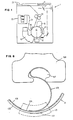
- Fig. 4 is a sectional illustration of the electrophotographic drum tensioning device of Fig. 3 showing the photoconductor sleeve on the drum, the elongated bar and the S-shaped spring;
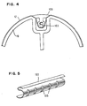
- Fig. 5 is a perspective illustration of the S-shaped spring used in Fig. 4;
- Fig. 6 is an expanded sectional illustration of Fig. 4 showing in detail the S-shaped spring making electrical contact with the elongated bar and the photoconductor sleeve aluminium ground plane area;
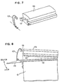
- Fig. 7 is a detailed perspective view of the latching mechanism showing the latching hook disengaged from the latching loop; and
- Fig. 8 is a detailed side view of the latching mechanism showing the latching hook in relation to the latching loop.
- Fig. 1 shows an electrophotographic copier 1 which can employ an embodiment of the present invention. Copier 1 includes a
photoconductor 12 carried by anelectrophotographic drum 10. To make a copy of an original document 11, an electrostatic latent image of the page must be produced. This is accomplished by having an image area ofphotoconductor 12 first subjected to uniform electrostatic charge atcorona station 14. The image area onphotoconductor 12 is then selectively imaged by light reflected from the original document 11. The resulting electrostatic latent image onphotoconductor 12 is then toned by adeveloper 13 by appling a toner to the electrostatic image. - The developed image is then removed from the photoconductor image area to a copy sheet at
transfer station 16 for subsequent fixing. In addition, the image area may be subjected to cleaning atstation 15, as thedrum 10 rotates in the clockwise direction at a constant speed. Sheets of paper are supplied, one sheet at a time, frombin 20. These sheets of paper followpath 21, including passing throughhot fusing rolls 22, to reachexit pocket 23. - Details of an electrophotographic copier are well known to those skilled in the art and form no part of this invention. It is to be understood that a variety of techniques exists for performing the various individual functions of the electrophotographic process identified.
- Copier 1 may employ a
flexible photoconductor 12 of the type having a form of closed loop sleeve. As will be described hereinafter, this type of photoconductor is inherently simpler and less expensive to manufacture than the prior coating-on-drum type photoconductor design having an aluminum drum and on which a photosensitive coating is directly applied. Similarly, this flexible photoconductor sleeve design also has a cost advantage over incrementally moveable photoconductor rolls. More specifically, the cost of an automatically incremented photoconductor roll system may well approximate the manufacturing cost of an entire low-cost copier. For these reasons, this type of photoconductor offers advantages of both lower initial machine cost and lower subsequent photoconductor replacement cost to a customer. - Referring to Figs. 2 and 6,
photoconductor sleeve 12 has aplastic film backing 122, which is sold commonly under the trademark Mylar, and is formed from a photoconductor sheet by bonding its two ends usingadhesive tape 128. A layer ofaluminum 124 is deposited on the Mylar backing 122 to form an ground plane. Aphotosensitive layer 126, such as zinc oxide, is then deposited on top ofaluminum layer 124 on the outside surface ofphotoconductor sleeve 12. To facilitate electrical connection toaluminum ground plane 124, a strip of photoconductor onarea 125 along the length ofphotoconductor sleeve 12 is removed exposing thealuminum ground plane 124. - Referring to Fig. 3, drum 10 is a specially designed device having thereon a unique photoconductor sleeve tensioning feature. The
drum 10 has achannel 102 on the cylindrical drum periphery thereof, running substantially parallel to the drum central axis 104, along the length of thedrum 10. Anelongated bar 106 having a cross sectional configuration for fitting within thechannel 102, may be pivotally mounted at one of its ends at aninternal point 108 ondrum 10. Referring to Figs. 7 and 8, a latchinghook 101 may also be provided at the other end ofbar 106. Latchingloop 109 pivotally mounted at a point onlever 110, which in turn is mounted ondrum 10, is placed overhook 101 ofbar 106 for securing it to drum 10 whenbar 106 is in position withinchannel 102. Latching is accomplished by movinglever 110 from an unlatched position to a latched position. Further,elongated bar 106 is designed to fit tightly withinchannel 102 so as to prevent toner particles or carrier beads, which are used in developer station 13 (Fig. 1), from entering thechannel 102. A slot 107 (Fig. 6) along the underside of the elongated bar may be also provided to engage one of two transverse ends of S-shapedspring 103 which is to be described immediately below. - Referring also to Fig. 4, a
spring 103 is positioned onbar 106 totension photoconductor sleeve 12 in response to forcing thesleeve 12 partially into thechannel 102 by thebar 106. As shown in Fig. 5, thespring 103 is an elongated structure having a substantially S-shaped cross section along thechannel 102.Elongated spring 103 may also containslots 105 along its length so as to provide greater flexibility thereby accommodating wider tolerances in the diameter ofsleeve 12 while maintaining proper even tension onsleeve 12 around the periphery ofdrum 10.Such springs 103 may be made of electrically conductive material, i.e., metal, and is attached also for establishing an electrical connection between thealuminum layer 124 of thesleeve 12 and thedrum 10 by way ofbar 106 when thesleeve 12 is forced partially into thechannel 102 by thebar 106. - Referring to Fig. 6,
elongated spring 103 has one of its two transverse ends fitted intoslot 107 ofbar 106, and the other in contact with exposedaluminum area 125 ofaluminum ground plane 124. The variable tensioning action ofelongated spring 103 establishes a good electrical connection for proper grounding ofaluminum layer 124 ofphotoconductor sleeve 12. The same action also evenly holdsflexible photoconductor sleeve 12 radially inward on the periphery ofdrum 10 for use in copier 1. - As referred to above, because of the variable tension provided by
spring 103, proper electrical contact and tension of thephotoconductor sleeve 12 can also be maintained forsleeves 12 having slightly different diameters. This advantage translates into a reduction in the tolerances on the manufacture of thephotoconductor sleeve 12, thus further reducing its cost substantially relative to prior photoconductors. - This type of low
cost photoconductor sleeve 12, however, must be replaced periodically. Typically,such photoconductor sleeve 12 is replaced at the usage rate of about every 10,000 or more copies. Moreover, the useful life of aphotoconductor sleeve 12 may be cut short substantially because of physical damage to thephotoconductor sleeve 12 due to foreign ojects, such as paper clips, pens, etc., which fall inadvertently into copier 1. In addition, photoconductor replacement may also be necessitated by damage to thephotoconductor sleeve 12 caused during the clearance of a paper jam performed by an operator. Most photoconductor replacements heretofore have been performed by trained service personnel. The photoconductor tensioning device according to the present invention can be operated simply, easily and quickly to replace aphotoconductor sleeve 12 by an untrained operator. Replacement ofsuch sleeve 12 will be described next. - To replace
photoconductor sleeve 12, theelectrophotographic drum 10 is either removed entirely from copier 1 or otherwise rendered accessible in cantilever fashion within copier 1.Elongated bar 106 is released and moved pivotally from its latched position to an open position. The usedphotoconductor sleeve 12 is removed by sliding it out from the upper end ofdrum 10 remote from the pivot. Anew photoconductor sleeve 12 is removed from its protective shipping jacket, and is then slid overdrum 10 withbar 106 still open.Area 125, which exposes thealuminum ground plane 124 along the length ofphotoconductor 12, is pressed intochannel 102. Pivoting atpoint 108,bar 106 is then closed. The "scissoring" action ofbar 102 as it is being forced intochannel 102, brings thetensioning spring 103 into intimate contact witharea 125 ofaluminum ground plane 124. This electrical contact onarea 125 made byspring 103 grounds thealuminum layer 124 ofsleeve 12 by way ofbar 106,drum 10, and the drum bearings (not shown) to the main frame (not shown) of copier 1. This action also automatically draws thesleeve 12 tightly around the cylindrical surface ofdrum 10. Latchingloop 109 is then placed overhook 101 ofbar 106 to secure thebar 106 to drum 10 using lever 110 (Fig. 8).Drum 10 withnew photoconductor sleeve 12 is then returned to its operating position in copier 1. - The above described photoconductor tensioning device makes possible this easy to follow
photoconductor sleeve 12 replacement procedure. Replacement ofphotoconductor sleeve 12 using this procedure allows the operator both hands free to install thenew photoconductor sleeve 12. Thedrum 10 and bar 106 remain one integral unit during replacement. In addition, electrical disconnection and reconnection to thephotoconductor sleeve 12 is accomplished automatically and without loose parts to be misplaced or lost. In short, the photoconductor tensioning device according to the present invention allows an untrained operator to replace aphotoconductor sleeve 12 easily and quickly in a simple to follow replacement procedure. - Although the photoconductor clamping device, also known as tensioning device in Fig. 3 is shown and described in connection for use in a copier, it is clear that the device is equally applicable in electrophotographic printer applications.
Claims (6)
Applications Claiming Priority (2)
| Application Number | Priority Date | Filing Date | Title |
|---|---|---|---|
| US06/217,965 US4357093A (en) | 1980-12-18 | 1980-12-18 | Photoconductor tensioning device |
| US217965 | 1980-12-18 |
Publications (2)
| Publication Number | Publication Date |
|---|---|
| EP0054639A1 EP0054639A1 (en) | 1982-06-30 |
| EP0054639B1 true EP0054639B1 (en) | 1984-04-04 |
Family
ID=22813204
Family Applications (1)
| Application Number | Title | Priority Date | Filing Date |
|---|---|---|---|
| EP81108128A Expired EP0054639B1 (en) | 1980-12-18 | 1981-10-09 | Imaging element for an electrophotographic machine |
Country Status (4)
| Country | Link |
|---|---|
| US (1) | US4357093A (en) |
| EP (1) | EP0054639B1 (en) |
| JP (1) | JPS57102668A (en) |
| DE (1) | DE3162982D1 (en) |
Families Citing this family (16)
| Publication number | Priority date | Publication date | Assignee | Title |
|---|---|---|---|---|
| JPS59191077A (en) * | 1983-04-14 | 1984-10-30 | Konishiroku Photo Ind Co Ltd | Recording device |
| JPS60112265U (en) * | 1984-01-05 | 1985-07-30 | 株式会社 巴川製紙所 | Belt-shaped photoreceptor |
| JPH0320850Y2 (en) * | 1985-01-14 | 1991-05-07 | ||
| JPH0320848Y2 (en) * | 1985-01-14 | 1991-05-07 | ||
| JPH0320849Y2 (en) * | 1985-01-14 | 1991-05-07 | ||
| JPH0320852Y2 (en) * | 1985-01-14 | 1991-05-07 | ||
| JPH0320851Y2 (en) * | 1985-01-14 | 1991-05-07 | ||
| US5081507A (en) * | 1987-11-16 | 1992-01-14 | Xerox Corporation | Registration apparatus for a printing system |
| DE3928640A1 (en) * | 1989-08-30 | 1991-03-14 | Roland Man Druckmasch | RUBBER BLANKET CYLINDERS FOR ARC ROTATION OFFSET PRINTING MACHINES |
| US5052120A (en) * | 1990-04-16 | 1991-10-01 | Eastman Kodak Company | Sheet positioning, clamping, and tensioning means |
| US5255056A (en) * | 1990-04-20 | 1993-10-19 | Minnesota Mining And Manufacturing Co. | Photoconductor film clamping and tensioning system and method of use |
| US5177542A (en) * | 1991-10-07 | 1993-01-05 | Eastman Kodak Company | Method of xeroprinting |
| US5630197A (en) * | 1992-09-30 | 1997-05-13 | Hitachi Koki Co., Ltd. | Mounting device for interchangeably mounting different types of photoconductors |
| US5386273A (en) * | 1993-02-05 | 1995-01-31 | Xerox Corporation | Belt photoreceptor on cylindrical mandrel |
| US5666600A (en) * | 1996-01-11 | 1997-09-09 | Xerox Corporation | Mandrel with a retractable segment for mounting a belt photoreceptor on the mandrel |
| US6377772B1 (en) * | 2000-10-04 | 2002-04-23 | Nexpress Solutions Llc | Double-sleeved electrostatographic roller and method of using |
Family Cites Families (11)
| Publication number | Priority date | Publication date | Assignee | Title |
|---|---|---|---|---|
| US2085093A (en) * | 1933-09-06 | 1937-06-29 | Bell Telephone Labor Inc | Sheet holding means |
| US3408933A (en) * | 1966-03-24 | 1968-11-05 | Miehle Goss Dexter Inc | Continuous take-up clamping arrangement for blanket in printing press |
| US3438324A (en) * | 1967-01-18 | 1969-04-15 | Paper Converting Machine Co | Magnetic printing plate holddown means |
| US3536397A (en) * | 1967-10-13 | 1970-10-27 | Xerox Corp | Xerographic apparatus |
| US3646886A (en) * | 1968-05-10 | 1972-03-07 | Wood Industries Inc | Plate cylinder with interchangeable plate clamping device |
| US3764208A (en) * | 1970-12-29 | 1973-10-09 | Canon Kk | Developing device for use in electrophotographic copying machines |
| JPS5631591B2 (en) * | 1973-12-29 | 1981-07-22 | ||
| JPS50118730A (en) * | 1974-02-28 | 1975-09-17 | ||
| JPS52133113U (en) * | 1976-04-05 | 1977-10-08 | ||
| US4183652A (en) * | 1977-04-30 | 1980-01-15 | Ricoh Company, Ltd. | Photoconductor sheet clamp apparatus |
| DE2830955A1 (en) * | 1978-07-14 | 1980-01-24 | Olympia Werke Ag | ELECTROPHOTOGRAPHIC COPIER WITH A REPLACEABLE PHOTO CABLE |
-
1980
- 1980-12-18 US US06/217,965 patent/US4357093A/en not_active Expired - Fee Related
-
1981
- 1981-09-14 JP JP56144080A patent/JPS57102668A/en active Pending
- 1981-10-09 DE DE8181108128T patent/DE3162982D1/en not_active Expired
- 1981-10-09 EP EP81108128A patent/EP0054639B1/en not_active Expired
Also Published As
| Publication number | Publication date |
|---|---|
| EP0054639A1 (en) | 1982-06-30 |
| US4357093A (en) | 1982-11-02 |
| JPS57102668A (en) | 1982-06-25 |
| DE3162982D1 (en) | 1984-05-10 |
Similar Documents
| Publication | Publication Date | Title |
|---|---|---|
| EP0054639B1 (en) | Imaging element for an electrophotographic machine | |
| US5946529A (en) | Image forming apparatus using a roller type charging system | |
| US3989005A (en) | Oil metering blade device | |
| EP0395887B1 (en) | Conveying rotatable member and conveying apparatus | |
| JP3083000B2 (en) | Image forming device | |
| JPH02165182A (en) | Cleaning device of electrophotographic device | |
| EP0291319B1 (en) | Stripper finger mechanism | |
| US6601991B2 (en) | Roller device for an image transferring device | |
| US5623720A (en) | Method and apparatus for stripper bar rotation | |
| US4277164A (en) | Photocopier photoconductive sheet holding device | |
| US3918400A (en) | Blade mounting assemblies | |
| US3934113A (en) | Roll fuser apparatus and mounting arrangement therefor | |
| US4965633A (en) | Electrophotographic copier process kit having removable closure members | |
| EP0296334B1 (en) | Image transferring device for a copier | |
| US4087169A (en) | Transfer roller system | |
| JP2001117375A (en) | Image forming device | |
| JPS6334467B2 (en) | ||
| CA2183907C (en) | Force applying blade device exhibiting a reduced creep rate | |
| US3951538A (en) | Permanently nipped contact image fuser system incorporating a one-way clutch | |
| JPH0531148B2 (en) | ||
| US6178300B1 (en) | Photoreceptor web grounding structure of liquid electrophotographic printer | |
| CA1059573A (en) | Cleaning structure for an elastomeric fusing member | |
| CA1068769A (en) | Oil metering blade loading assembly | |
| JP3205964B2 (en) | Image forming device | |
| CA1059203A (en) | Oil metering blade holder assembly |
Legal Events
| Date | Code | Title | Description |
|---|---|---|---|
| PUAI | Public reference made under article 153(3) epc to a published international application that has entered the european phase |
Free format text: ORIGINAL CODE: 0009012 |
|
| 17P | Request for examination filed |
Effective date: 19811009 |
|
| AK | Designated contracting states |
Designated state(s): DE FR GB |
|
| GRAA | (expected) grant |
Free format text: ORIGINAL CODE: 0009210 |
|
| AK | Designated contracting states |
Designated state(s): DE FR GB |
|
| REF | Corresponds to: |
Ref document number: 3162982 Country of ref document: DE Date of ref document: 19840510 |
|
| ET | Fr: translation filed | ||
| PLBE | No opposition filed within time limit |
Free format text: ORIGINAL CODE: 0009261 |
|
| STAA | Information on the status of an ep patent application or granted ep patent |
Free format text: STATUS: NO OPPOSITION FILED WITHIN TIME LIMIT |
|
| 26N | No opposition filed | ||
| PGFP | Annual fee paid to national office [announced via postgrant information from national office to epo] |
Ref country code: GB Payment date: 19910923 Year of fee payment: 11 |
|
| PGFP | Annual fee paid to national office [announced via postgrant information from national office to epo] |
Ref country code: FR Payment date: 19911001 Year of fee payment: 11 |
|
| PGFP | Annual fee paid to national office [announced via postgrant information from national office to epo] |
Ref country code: DE Payment date: 19911102 Year of fee payment: 11 |
|
| PG25 | Lapsed in a contracting state [announced via postgrant information from national office to epo] |
Ref country code: GB Effective date: 19921009 |
|
| GBPC | Gb: european patent ceased through non-payment of renewal fee |
Effective date: 19921009 |
|
| PG25 | Lapsed in a contracting state [announced via postgrant information from national office to epo] |
Ref country code: FR Effective date: 19930630 |
|
| PG25 | Lapsed in a contracting state [announced via postgrant information from national office to epo] |
Ref country code: DE Effective date: 19930701 |
|
| REG | Reference to a national code |
Ref country code: FR Ref legal event code: ST |