EP0054611B1 - A tool holder - Google Patents
A tool holder Download PDFInfo
- Publication number
- EP0054611B1 EP0054611B1 EP81106232A EP81106232A EP0054611B1 EP 0054611 B1 EP0054611 B1 EP 0054611B1 EP 81106232 A EP81106232 A EP 81106232A EP 81106232 A EP81106232 A EP 81106232A EP 0054611 B1 EP0054611 B1 EP 0054611B1
- Authority
- EP
- European Patent Office
- Prior art keywords
- axis
- insert
- pin
- body portion
- threaded
- Prior art date
- Legal status (The legal status is an assumption and is not a legal conclusion. Google has not performed a legal analysis and makes no representation as to the accuracy of the status listed.)
- Expired
Links
Images

Classifications
-
- B—PERFORMING OPERATIONS; TRANSPORTING
- B23—MACHINE TOOLS; METAL-WORKING NOT OTHERWISE PROVIDED FOR
- B23B—TURNING; BORING
- B23B27/00—Tools for turning or boring machines; Tools of a similar kind in general; Accessories therefor
- B23B27/14—Cutting tools of which the bits or tips or cutting inserts are of special material
- B23B27/16—Cutting tools of which the bits or tips or cutting inserts are of special material with exchangeable cutting bits or cutting inserts, e.g. able to be clamped
- B23B27/1662—Cutting tools of which the bits or tips or cutting inserts are of special material with exchangeable cutting bits or cutting inserts, e.g. able to be clamped with plate-like cutting inserts clamped against the walls of the recess in the shank by a clamping member acting upon the wall of a hole in the cutting insert
-
- B—PERFORMING OPERATIONS; TRANSPORTING
- B23—MACHINE TOOLS; METAL-WORKING NOT OTHERWISE PROVIDED FOR
- B23B—TURNING; BORING
- B23B2205/00—Fixation of cutting inserts in holders
- B23B2205/08—Fixation of cutting inserts in holders using an eccentric
-
- Y—GENERAL TAGGING OF NEW TECHNOLOGICAL DEVELOPMENTS; GENERAL TAGGING OF CROSS-SECTIONAL TECHNOLOGIES SPANNING OVER SEVERAL SECTIONS OF THE IPC; TECHNICAL SUBJECTS COVERED BY FORMER USPC CROSS-REFERENCE ART COLLECTIONS [XRACs] AND DIGESTS
- Y10—TECHNICAL SUBJECTS COVERED BY FORMER USPC
- Y10T—TECHNICAL SUBJECTS COVERED BY FORMER US CLASSIFICATION
- Y10T407/00—Cutters, for shaping
- Y10T407/19—Rotary cutting tool
- Y10T407/1906—Rotary cutting tool including holder [i.e., head] having seat for inserted tool
- Y10T407/1934—Rotary cutting tool including holder [i.e., head] having seat for inserted tool with separate means to fasten tool to holder
- Y10T407/1936—Apertured tool
-
- Y—GENERAL TAGGING OF NEW TECHNOLOGICAL DEVELOPMENTS; GENERAL TAGGING OF CROSS-SECTIONAL TECHNOLOGIES SPANNING OVER SEVERAL SECTIONS OF THE IPC; TECHNICAL SUBJECTS COVERED BY FORMER USPC CROSS-REFERENCE ART COLLECTIONS [XRACs] AND DIGESTS
- Y10—TECHNICAL SUBJECTS COVERED BY FORMER USPC
- Y10T—TECHNICAL SUBJECTS COVERED BY FORMER US CLASSIFICATION
- Y10T407/00—Cutters, for shaping
- Y10T407/22—Cutters, for shaping including holder having seat for inserted tool
- Y10T407/2272—Cutters, for shaping including holder having seat for inserted tool with separate means to fasten tool to holder
- Y10T407/2274—Apertured tool
- Y10T407/2276—Apertured tool with means projecting through aperture to force tool laterally against reaction surface
-
- Y—GENERAL TAGGING OF NEW TECHNOLOGICAL DEVELOPMENTS; GENERAL TAGGING OF CROSS-SECTIONAL TECHNOLOGIES SPANNING OVER SEVERAL SECTIONS OF THE IPC; TECHNICAL SUBJECTS COVERED BY FORMER USPC CROSS-REFERENCE ART COLLECTIONS [XRACs] AND DIGESTS
- Y10—TECHNICAL SUBJECTS COVERED BY FORMER USPC
- Y10T—TECHNICAL SUBJECTS COVERED BY FORMER US CLASSIFICATION
- Y10T407/00—Cutters, for shaping
- Y10T407/22—Cutters, for shaping including holder having seat for inserted tool
- Y10T407/2272—Cutters, for shaping including holder having seat for inserted tool with separate means to fasten tool to holder
- Y10T407/228—Rotatable cam clamp element
Definitions
- This invention relates to a tool holder and more particularly to a tool holder adapted releasably to hold a disposable cutting insert in a seat or recess formed in the shank thereof.
- Cutting tools of the aforesaid type typically have three or in some instances four components-a shank, a retention pin, a disposable cutting insert made of a very hard cutting material such as a suitable metallic carbide, and if necessary, a seat or seating member for the insert.
- the shank is formed with a recess to provide a seating face and a supporting shoulder for the insert or for the insert and the seating member.
- the retention pin is typically adjustably secured at one end thereof in a threaded bore formed in the shank. The other end of the pin projects into a hole in the insert.
- the design of the assemblage is such that as the retention pin is threaded into the bore in the shank, it forces the cutting insert against the supporting shoulder of the shank and locks it in the operating position.
- U.S.A. Patent No. 3,533,150 discloses a tool holder in which the retention pin when fully seated, moves axially to cause the head portion thereof to force the cutter insert into snug engagement with the shoulder.
- U.S.A. Patent No. 3,097,417 discloses a tool holder wherein the retention pin has an eccentrically positioned head portion, whereby rotation of the pin causes the head portion to force an insert against a supporting shoulder.
- U.S.A. Patent No. 3,341,920 discloses a retention pin which acts as a lever with its fulcrum at its lower or threaded end, laterally to displace its head portion toward a locking shoulder to secure a cutter insert in place.
- U.S.A. Patent No. 3,654,682 discloses a retention pin which provides a fulcrum intermediate its ends to force a cutter insert against a shoulder of a recess in the shank.
- the prior patents disclose a holder for holding a disposable cutting insert, the insert having an axial hole therein, the holder comprising a shank having a recess therein to provide a seating face and at least one supporting shoulder for supporting the cutting insert, the shank having a threaded bore therein, the bore being substantially normal to the seating face and adapted for alignment with the hole in the insert, the holder further comprising a theaded retention pin engaging the threaded bore, the pin having a cylindrical head portion adapted to engage the hole in the insert.
- a principal object of the present invention is to provide a cutting tool of the aforesaid type wherein the retention pin is simpler in design and accordingly, less expensive to fabricate, than prior proposed arrangement.
- the retention pin is fabricated from a blank having a cylindrical body portion having a first axis concurrent with the axis of the cylindrical head portion thereof, the body portion being threaded on a second axis angularly disposed with respect to the first axis and intersecting the same, so that when the pin is threaded into the bore the head portion rotates about the second axis, thereby forcing the cutting insert against the supporting shoulder while drawing the insert into engagement with the seating face.
- the second angularly disposed axis, along which the body portion of the pin is threaded, intersects the first axis thereof at about the mid-point of the cylindrical body portion.
- the moment of the force which is achieved as the threaded pin is screwed into the bore is centered about the mid-length of the body portion, thereby to create a moment arm of maximum length and consequently a more snug engagement of the insert against the shoulder of the shank than has been possible heretofore.
- the second axis on which the body portion of the retention pin is threaded is preferably disposed at an angle of approximately two degrees with respect to the first axis of the body portion prior to theading.
- the holder may optionally include a seating member adapted to rest on the seating face, wherein the cutting insert is supported by the seating member.
- the invention also provides a retention pin for use in a holder for holding a disposable cutting insert, the insert having an axial hole therein, the holder comprising a shank having a recess therein to provide a seating face and at least one supporting shoulder for supporting the cutting insert, the shank having a threaded bore therein, the bore 26 being substantially normal to the seating face and adapted for alignment with the hole in the insert, the retention pin comprising a cylindrical head adapted to be received in the hole in the insert and a cylindrical body portion, the body portion having a first axis concurrent with the axis of the head, the body portion being threaded on a second axis angularly disposed with respect to the first axis and intersecting the same, whereby threading the pin into the threaded bore causes the head of the pin to rotate about the second axis as the pin is received in the bore.
- the bore in the shank has but one axis and thus requires only one drilling and tapping operation.
- the retention pin will tip instead of just laterally move as it seats the cutter insert snugly against the shoulder of the recess in the shank.
- the retention pin is fabricated from a blank having a cylindrical head portion which initially, is coaxially disposed with respect to the cylindrical body portion of the pin prior to any threading thereof.
- a tool holder in accordance with the present invention comprises four principal parts-a cutting insert 10, a cutting insert seat or seating member 11, a retention pin 12 and a cutting tool shank 13.
- the cutting insert 10 is of the disposable type, preferably made of a very hard cutting material such as a suitable metallic carbide, and has oppositely spaced parallel faces 14 and peripheral surfaces 15 forming cutting edges 16 as shown.
- a central hole 18 is formed perpendicular to each of the parallel faces 14.
- the cutting tool shank 13 contains a recess 20 at the head portion thereof forming supporting shoulders 22 and a seating face 24.
- the shank is provided with a threaded bore 26 having an axis 28 which is substantially normal to the seating face 24 and extends completely through the shank, as shown.
- the terms "upper” and “lower” are used herein with reference to the position of the tool holder and principal parts thereof as they are shown in the drawings. The tool may, of course, assume any position in a cutting or machining operation.
- the insert 10 and seat 11 are fastened in the recess 20 by the retention pin 12 which has a hexagonal socket 30 or other suitable means for engaging an adjusting tool formed in its upper or, if preferred, in its lower end.
- the retention pin 12 is illustrated in Figure 2 in its blank form, i.e., prior to threading. It comprises an upper cylindrical head portion 32 which is adapted to have a slack fit in the hole 18 of the insert 10.
- the blank further comprises a lower concentric cylindrical body portion 34 and a flange 36 at the junction of the upper and lower cylindrical portions 32, 34, the flange 36 being adapted to fit in a counter bore 38 in the seat 11 (see Figure 6).
- Portions 32, 34 and 36 of the pin 12 all have a common axis 40.
- the threading of the pin 12 is an important feature of the present invention and is illustrated in Figure 3. It is accomplished by tilting the pin 12 by approximately two degrees about the centre point 42 of that portion of the axis 40 within the body portion 34 and then cutting a thread 44 on the resulting tilted axis 46.
- the centre axis of the thread 44 is thus directly on the axis 40 of the blank only at point 42. Because the thread axis 46 is tilted with respect to the blank axis 40, a portion 48 of the threads 44 at the lower end 34a of the body portion 34 are cut with some portions of their apices missing; the same occurs with respect to a portion 49 of the threads 44 at the upper end 34b of the body portion 34.
- the remaining portions 50, 51 of the thread 44 at the lower and upper ends 34a and 34b of the body portion 34, respectively, are cut with full apices.
- Figures 4, 5, 6 and 7 illustrate the relationship between the cutting insert 10, the retention pin 12 and the threaded bore 26 as the pin 12 is inserted into the bore 26.
- the head portion 32 rotates about axis 46 as the pin 12 draws the insert 10 into engagement with the seat 11.
- the head portion 32 is at its maximum outboard position 32a as shown in the dashed lines in Figure 4 and also in Figure 6. This position permits easy release of insert 10 so as to facilitate indexing thereof.
- the head portion 32 rotates about the axis 46 and thus moves to the right as shown in solid lines in Figure 4, thereby forcing the insert 10 against the shoulders 22.
- the head portion 32 makes full contact with hole 18, thereby to press insert 10 fully against shoulders 22, the projections of the three axes 28, 40, and 46 falling upon each other.
- the centre of thread 44 is directly on the blank axis 40 at point 42, a tilting moment about such point is achieved and this moment is centered about the point 42, i.e., about the mid-length of the body portion 34 of pin 12.
- the force vectors of this moment are represented by the arrows F in Figure 7.
- the construction creates the maximum.moment arm possible and consequently a very snug engagement of insert 10 against the shoulders 22.
- the two degree tilt of axis 46 with respect to axis 40 is not highly critical; the tilting could for example be selected to be anywhere in the range of 1 ⁇ 2 degrees.
Abstract
Description
- This invention relates to a tool holder and more particularly to a tool holder adapted releasably to hold a disposable cutting insert in a seat or recess formed in the shank thereof.
- Cutting tools of the aforesaid type typically have three or in some instances four components-a shank, a retention pin, a disposable cutting insert made of a very hard cutting material such as a suitable metallic carbide, and if necessary, a seat or seating member for the insert. The shank is formed with a recess to provide a seating face and a supporting shoulder for the insert or for the insert and the seating member. The retention pin is typically adjustably secured at one end thereof in a threaded bore formed in the shank. The other end of the pin projects into a hole in the insert. The design of the assemblage is such that as the retention pin is threaded into the bore in the shank, it forces the cutting insert against the supporting shoulder of the shank and locks it in the operating position.
- U.S.A. Patent No. 3,533,150 discloses a tool holder in which the retention pin when fully seated, moves axially to cause the head portion thereof to force the cutter insert into snug engagement with the shoulder. U.S.A. Patent No. 3,097,417 discloses a tool holder wherein the retention pin has an eccentrically positioned head portion, whereby rotation of the pin causes the head portion to force an insert against a supporting shoulder.
- The following patents disclose retention pins having frusto-conical or wedging portions to force a cutting insert against a supporting shoulder: U.S.A. Patent No. 3,284,874; U.S.A. Patent No. 3,310,859; U.S.A. Patent No. 3,341,919 and U.S.A. Patent No. 3,613,198.
- U.S.A. Patent No. 3,341,920 discloses a retention pin which acts as a lever with its fulcrum at its lower or threaded end, laterally to displace its head portion toward a locking shoulder to secure a cutter insert in place. U.S.A. Patent No. 3,654,682 discloses a retention pin which provides a fulcrum intermediate its ends to force a cutter insert against a shoulder of a recess in the shank.
- Thus, in summary the prior patents disclose a holder for holding a disposable cutting insert, the insert having an axial hole therein, the holder comprising a shank having a recess therein to provide a seating face and at least one supporting shoulder for supporting the cutting insert, the shank having a threaded bore therein, the bore being substantially normal to the seating face and adapted for alignment with the hole in the insert, the holder further comprising a theaded retention pin engaging the threaded bore, the pin having a cylindrical head portion adapted to engage the hole in the insert.
- A principal object of the present invention is to provide a cutting tool of the aforesaid type wherein the retention pin is simpler in design and accordingly, less expensive to fabricate, than prior proposed arrangement.
- In the present invention in a tool holder of the type disclosed above, the retention pin is fabricated from a blank having a cylindrical body portion having a first axis concurrent with the axis of the cylindrical head portion thereof, the body portion being threaded on a second axis angularly disposed with respect to the first axis and intersecting the same, so that when the pin is threaded into the bore the head portion rotates about the second axis, thereby forcing the cutting insert against the supporting shoulder while drawing the insert into engagement with the seating face.
- Preferably, the second angularly disposed axis, along which the body portion of the pin is threaded, intersects the first axis thereof at about the mid-point of the cylindrical body portion. Thus, the moment of the force which is achieved as the threaded pin is screwed into the bore, is centered about the mid-length of the body portion, thereby to create a moment arm of maximum length and consequently a more snug engagement of the insert against the shoulder of the shank than has been possible heretofore.
- The second axis on which the body portion of the retention pin is threaded is preferably disposed at an angle of approximately two degrees with respect to the first axis of the body portion prior to theading.
- The holder may optionally include a seating member adapted to rest on the seating face, wherein the cutting insert is supported by the seating member.
- The invention also provides a retention pin for use in a holder for holding a disposable cutting insert, the insert having an axial hole therein, the holder comprising a shank having a recess therein to provide a seating face and at least one supporting shoulder for supporting the cutting insert, the shank having a threaded bore therein, the
bore 26 being substantially normal to the seating face and adapted for alignment with the hole in the insert, the retention pin comprising a cylindrical head adapted to be received in the hole in the insert and a cylindrical body portion, the body portion having a first axis concurrent with the axis of the head, the body portion being threaded on a second axis angularly disposed with respect to the first axis and intersecting the same, whereby threading the pin into the threaded bore causes the head of the pin to rotate about the second axis as the pin is received in the bore. - It will be appreciated that in a preferred embodiment of the invention the bore in the shank has but one axis and thus requires only one drilling and tapping operation. Also in the preferred embodiment the retention pin will tip instead of just laterally move as it seats the cutter insert snugly against the shoulder of the recess in the shank. Furthermore in the preferred embodiment the retention pin is fabricated from a blank having a cylindrical head portion which initially, is coaxially disposed with respect to the cylindrical body portion of the pin prior to any threading thereof.
- In order that the invention may be more readily understood, and so that further features thereof may be appreciated the invention will now be described by way of example with reference to the accompanying drawings, in which
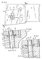
- Figure 1 is an exploded perspective view of a tool holder in accordance with the present invention with the seating member shown in phantom,
- Figure 2 is a perspective view of the blank from which the retention pin is fabricated,
- Figure 3 is a side elevational view of the retention pin after it has been threaded,
- Figure 4 is a generally schematic top view of the holder illustrating the cutting insert in its fully seated position in solid lines and in a released position in dashed lines, the location of the head portion of the retention pin being similarly illustrated for each of such two positions,
- Figure 5 is a top plan view of the tool holder illustrating the cutting insert in its fully seated position,
- Figure 6 is a sectional view taken on line 6-6 of Figure 5 and illustrating the positions of the retention pin and the cutting insert when the latter is in a released position, and
- Figure 7 is a view similar to Figure 6 taken when the retention pin and cutting insert are in the fully seated position.
- Referring to the drawings and initially referring particularly to Figure 1, it can be seen that a tool holder in accordance with the present invention comprises four principal parts-a
cutting insert 10, a cutting insert seat orseating member 11, aretention pin 12 and acutting tool shank 13. Thecutting insert 10 is of the disposable type, preferably made of a very hard cutting material such as a suitable metallic carbide, and has oppositely spacedparallel faces 14 andperipheral surfaces 15 formingcutting edges 16 as shown. Acentral hole 18 is formed perpendicular to each of theparallel faces 14. - The
cutting tool shank 13 contains arecess 20 at the head portion thereof forming supportingshoulders 22 and aseating face 24. The shank is provided with a threadedbore 26 having anaxis 28 which is substantially normal to theseating face 24 and extends completely through the shank, as shown. The terms "upper" and "lower" are used herein with reference to the position of the tool holder and principal parts thereof as they are shown in the drawings. The tool may, of course, assume any position in a cutting or machining operation. - The
insert 10 andseat 11 are fastened in therecess 20 by theretention pin 12 which has ahexagonal socket 30 or other suitable means for engaging an adjusting tool formed in its upper or, if preferred, in its lower end. - The
retention pin 12 is illustrated in Figure 2 in its blank form, i.e., prior to threading. It comprises an uppercylindrical head portion 32 which is adapted to have a slack fit in thehole 18 of theinsert 10. The blank further comprises a lower concentriccylindrical body portion 34 and aflange 36 at the junction of the upper and lowercylindrical portions flange 36 being adapted to fit in acounter bore 38 in the seat 11 (see Figure 6).Portions pin 12 all have acommon axis 40. - The threading of the
pin 12 is an important feature of the present invention and is illustrated in Figure 3. It is accomplished by tilting thepin 12 by approximately two degrees about thecentre point 42 of that portion of theaxis 40 within thebody portion 34 and then cutting athread 44 on the resultingtilted axis 46. The centre axis of thethread 44 is thus directly on theaxis 40 of the blank only atpoint 42. Because thethread axis 46 is tilted with respect to theblank axis 40, aportion 48 of thethreads 44 at the lower end 34a of thebody portion 34 are cut with some portions of their apices missing; the same occurs with respect to aportion 49 of thethreads 44 at theupper end 34b of thebody portion 34. Theremaining portions thread 44 at the lower andupper ends 34a and 34b of thebody portion 34, respectively, are cut with full apices. - Figures 4, 5, 6 and 7 illustrate the relationship between the
cutting insert 10, theretention pin 12 and the threadedbore 26 as thepin 12 is inserted into thebore 26. Inasmuch as thethread 44 is cut on theaxis 46, which is angularly disposed with respect to theaxis 40, when thepin 12 is inserted into thebore 26, thehead portion 32 rotates aboutaxis 46 as thepin 12 draws theinsert 10 into engagement with theseat 11. Thus, when thepin 12 is somewhat less than 90° removed from its fully inserted position, thehead portion 32 is at itsmaximum outboard position 32a as shown in the dashed lines in Figure 4 and also in Figure 6. This position permits easy release ofinsert 10 so as to facilitate indexing thereof. - As
pin 12 is further rotated to achieve its fully seated position, thehead portion 32 rotates about theaxis 46 and thus moves to the right as shown in solid lines in Figure 4, thereby forcing theinsert 10 against theshoulders 22. As viewed in Figure 7, thehead portion 32 makes full contact withhole 18, thereby to press insert 10 fully againstshoulders 22, the projections of the threeaxes thread 44 is directly on theblank axis 40 atpoint 42, a tilting moment about such point is achieved and this moment is centered about thepoint 42, i.e., about the mid-length of thebody portion 34 ofpin 12. The force vectors of this moment are represented by the arrows F in Figure 7. The construction creates the maximum.moment arm possible and consequently a very snug engagement ofinsert 10 against theshoulders 22. - The two degree tilt of
axis 46 with respect toaxis 40 is not highly critical; the tilting could for example be selected to be anywhere in the range of 1

Claims (7)
Priority Applications (1)
| Application Number | Priority Date | Filing Date | Title |
|---|---|---|---|
| AT81106232T ATE6600T1 (en) | 1980-12-22 | 1981-08-10 | TOOL HOLDER. |
Applications Claiming Priority (2)
| Application Number | Priority Date | Filing Date | Title |
|---|---|---|---|
| US06/218,579 US4364693A (en) | 1980-12-22 | 1980-12-22 | Tool holder |
| US218579 | 1980-12-22 |
Publications (2)
| Publication Number | Publication Date |
|---|---|
| EP0054611A1 EP0054611A1 (en) | 1982-06-30 |
| EP0054611B1 true EP0054611B1 (en) | 1984-03-14 |
Family
ID=22815653
Family Applications (1)
| Application Number | Title | Priority Date | Filing Date |
|---|---|---|---|
| EP81106232A Expired EP0054611B1 (en) | 1980-12-22 | 1981-08-10 | A tool holder |
Country Status (8)
| Country | Link |
|---|---|
| US (1) | US4364693A (en) |
| EP (1) | EP0054611B1 (en) |
| JP (1) | JPS57107707A (en) |
| AT (1) | ATE6600T1 (en) |
| AU (1) | AU538921B2 (en) |
| CA (1) | CA1158035A (en) |
| DE (1) | DE3162668D1 (en) |
| ZA (1) | ZA815024B (en) |
Cited By (1)
| Publication number | Priority date | Publication date | Assignee | Title |
|---|---|---|---|---|
| DE10345690B4 (en) * | 2002-10-28 | 2006-09-28 | Kennametal Inc. | Device for clamping an insert in a tool holder |
Families Citing this family (9)
| Publication number | Priority date | Publication date | Assignee | Title |
|---|---|---|---|---|
| SE421110B (en) * | 1980-04-03 | 1981-11-30 | Seco Tools Ab | VERKTYGSBERARE |
| US4470732A (en) * | 1980-12-22 | 1984-09-11 | Lindsay Harold W | Tool holder with retaining lip |
| US4602897A (en) * | 1984-04-25 | 1986-07-29 | Iscar Metals, Inc. | Cutting insert and grooving cutter |
| US5004378A (en) * | 1988-05-19 | 1991-04-02 | Mitsubishi Metal Corporation | Clamped cutting tool |
| US5062742A (en) * | 1990-05-24 | 1991-11-05 | Pfauter-Maag Cutting Tools Limited Partnership | Angular interlock for the replaceable wafer of a shaper cutter |
| SE506525C2 (en) * | 1996-11-15 | 1997-12-22 | Erik Schmidt | clamping |
| US7213623B2 (en) * | 2004-01-20 | 2007-05-08 | Shinn Rickey D | Stump cutting device with load-distributing tooth sockets |
| SE529311C2 (en) * | 2005-12-05 | 2007-07-03 | Seco Tools Ab | A chip separation tool where the threaded joint is arranged to allow winding of the locking screw |
| US8616809B2 (en) * | 2007-01-17 | 2013-12-31 | James F. Farrell | Toolholder |
Family Cites Families (11)
| Publication number | Priority date | Publication date | Assignee | Title |
|---|---|---|---|---|
| US1240699A (en) * | 1916-05-11 | 1917-09-18 | Erwin S Frey | Tool-holder. |
| US3097417A (en) * | 1957-10-25 | 1963-07-16 | Tool holder with replaceable tip | |
| US3341919A (en) * | 1963-08-01 | 1967-09-19 | Futurmill Inc | Tool holder arrangement |
| US3341920A (en) * | 1965-02-16 | 1967-09-19 | Gen Electric | Cutting tool |
| US3284874A (en) * | 1965-11-22 | 1966-11-15 | De Vlieg Machine Co | Cutting tool with removal cutter element |
| US3310859A (en) * | 1966-05-03 | 1967-03-28 | Le Roy H Diemond | Cutting tool |
| GB1239390A (en) * | 1967-11-08 | 1971-07-14 | ||
| SE324272B (en) * | 1968-09-24 | 1970-05-25 | Fagersta Bruks Ab | |
| US3613198A (en) * | 1969-09-19 | 1971-10-19 | Emil W Weber | Cutting tool assembly |
| US3654682A (en) * | 1970-09-01 | 1972-04-11 | Edward H Newbould | Tool holder |
| BE793105A (en) * | 1971-12-24 | 1973-04-16 | Walter Gmbh Montanwerke | EXCHANGEABLE CUTTING INSERT MILLING TOOL |
-
1980
- 1980-12-22 US US06/218,579 patent/US4364693A/en not_active Expired - Fee Related
-
1981
- 1981-07-22 ZA ZA815024A patent/ZA815024B/en unknown
- 1981-07-22 CA CA000382203A patent/CA1158035A/en not_active Expired
- 1981-08-10 EP EP81106232A patent/EP0054611B1/en not_active Expired
- 1981-08-10 AT AT81106232T patent/ATE6600T1/en not_active IP Right Cessation
- 1981-08-10 DE DE8181106232T patent/DE3162668D1/en not_active Expired
- 1981-08-24 AU AU74466/81A patent/AU538921B2/en not_active Ceased
- 1981-09-25 JP JP56150821A patent/JPS57107707A/en active Pending
Cited By (1)
| Publication number | Priority date | Publication date | Assignee | Title |
|---|---|---|---|---|
| DE10345690B4 (en) * | 2002-10-28 | 2006-09-28 | Kennametal Inc. | Device for clamping an insert in a tool holder |
Also Published As
| Publication number | Publication date |
|---|---|
| AU538921B2 (en) | 1984-08-30 |
| ZA815024B (en) | 1982-07-28 |
| EP0054611A1 (en) | 1982-06-30 |
| JPS57107707A (en) | 1982-07-05 |
| ATE6600T1 (en) | 1984-03-15 |
| AU7446681A (en) | 1982-07-01 |
| US4364693A (en) | 1982-12-21 |
| DE3162668D1 (en) | 1984-04-19 |
| CA1158035A (en) | 1983-12-06 |
Similar Documents
| Publication | Publication Date | Title |
|---|---|---|
| US4470732A (en) | Tool holder with retaining lip | |
| CA1104330A (en) | Clamping mechanism for cutting insert | |
| US3341920A (en) | Cutting tool | |
| US4632593A (en) | Pin lock insert holder | |
| KR100314926B1 (en) | Cutting tools | |
| US4377292A (en) | Chuck assembly and collet | |
| US3491421A (en) | Tool holder for throw-away inserts | |
| EP0054611B1 (en) | A tool holder | |
| JPH0631504A (en) | Cutting tool with insert and spacer member | |
| EP0085156B1 (en) | Reaming tool with one cutting insert | |
| EP0219476B1 (en) | Locking pin for a tool holder | |
| US5167473A (en) | Unidirectional insert lock | |
| EP0446198B1 (en) | Quick-change mechanism with eccentric lock | |
| US4044440A (en) | Cutting tool | |
| US3946473A (en) | Cutting tools | |
| US4875812A (en) | Cutting tool employing a double pin retention assembly | |
| US4264245A (en) | Keyless holder for pin-type replaceable cutting inserts | |
| US5232317A (en) | Indexable spherical seat cutter | |
| US4204781A (en) | Clamping toolholder | |
| EP0638385A1 (en) | Cutting tool | |
| US4195955A (en) | Holder for pin-type replaceable cutting inserts | |
| US4909684A (en) | Retention knob for a tool holder and cutting tools employing the same | |
| CA1215825A (en) | Pin lock cutting tool | |
| EP0337970B1 (en) | Cutting tool employing a double pin retention assembly | |
| US2656591A (en) | Milling cutter |
Legal Events
| Date | Code | Title | Description |
|---|---|---|---|
| PUAI | Public reference made under article 153(3) epc to a published international application that has entered the european phase |
Free format text: ORIGINAL CODE: 0009012 |
|
| 17P | Request for examination filed |
Effective date: 19811005 |
|
| AK | Designated contracting states |
Designated state(s): AT BE CH DE FR GB IT LU NL SE |
|
| ITF | It: translation for a ep patent filed |
Owner name: JACOBACCI & PERANI S.P.A. |
|
| GRAA | (expected) grant |
Free format text: ORIGINAL CODE: 0009210 |
|
| AK | Designated contracting states |
Designated state(s): AT BE CH DE FR GB IT LI LU NL SE |
|
| REF | Corresponds to: |
Ref document number: 6600 Country of ref document: AT Date of ref document: 19840315 Kind code of ref document: T |
|
| REF | Corresponds to: |
Ref document number: 3162668 Country of ref document: DE Date of ref document: 19840419 |
|
| ET | Fr: translation filed | ||
| PGFP | Annual fee paid to national office [announced via postgrant information from national office to epo] |
Ref country code: DE Payment date: 19840808 Year of fee payment: 4 |
|
| PGFP | Annual fee paid to national office [announced via postgrant information from national office to epo] |
Ref country code: FR Payment date: 19840809 Year of fee payment: 4 |
|
| PGFP | Annual fee paid to national office [announced via postgrant information from national office to epo] |
Ref country code: CH Payment date: 19840820 Year of fee payment: 4 |
|
| PG25 | Lapsed in a contracting state [announced via postgrant information from national office to epo] |
Ref country code: LU Free format text: LAPSE BECAUSE OF NON-PAYMENT OF DUE FEES Effective date: 19840831 |
|
| PGFP | Annual fee paid to national office [announced via postgrant information from national office to epo] |
Ref country code: SE Payment date: 19840930 Year of fee payment: 4 Ref country code: BE Payment date: 19840930 Year of fee payment: 4 |
|
| PLBE | No opposition filed within time limit |
Free format text: ORIGINAL CODE: 0009261 |
|
| STAA | Information on the status of an ep patent application or granted ep patent |
Free format text: STATUS: NO OPPOSITION FILED WITHIN TIME LIMIT |
|
| 26N | No opposition filed | ||
| PGFP | Annual fee paid to national office [announced via postgrant information from national office to epo] |
Ref country code: AT Payment date: 19850819 Year of fee payment: 5 |
|
| PGFP | Annual fee paid to national office [announced via postgrant information from national office to epo] |
Ref country code: NL Payment date: 19850831 Year of fee payment: 5 |
|
| PG25 | Lapsed in a contracting state [announced via postgrant information from national office to epo] |
Ref country code: AT Effective date: 19860810 |
|
| PG25 | Lapsed in a contracting state [announced via postgrant information from national office to epo] |
Ref country code: SE Effective date: 19860811 |
|
| PG25 | Lapsed in a contracting state [announced via postgrant information from national office to epo] |
Ref country code: LI Effective date: 19860831 Ref country code: CH Effective date: 19860831 |
|
| BERE | Be: lapsed |
Owner name: LINDSAY HAROLD WILLIAM Effective date: 19860831 |
|
| PG25 | Lapsed in a contracting state [announced via postgrant information from national office to epo] |
Ref country code: NL Effective date: 19870301 |
|
| NLV4 | Nl: lapsed or anulled due to non-payment of the annual fee | ||
| GBPC | Gb: european patent ceased through non-payment of renewal fee | ||
| PG25 | Lapsed in a contracting state [announced via postgrant information from national office to epo] |
Ref country code: FR Free format text: LAPSE BECAUSE OF NON-PAYMENT OF DUE FEES Effective date: 19870430 |
|
| REG | Reference to a national code |
Ref country code: CH Ref legal event code: PL |
|
| PG25 | Lapsed in a contracting state [announced via postgrant information from national office to epo] |
Ref country code: DE Effective date: 19870501 |
|
| REG | Reference to a national code |
Ref country code: FR Ref legal event code: ST |
|
| PG25 | Lapsed in a contracting state [announced via postgrant information from national office to epo] |
Ref country code: GB Effective date: 19881121 |
|
| PG25 | Lapsed in a contracting state [announced via postgrant information from national office to epo] |
Ref country code: BE Effective date: 19890831 |
|
| EUG | Se: european patent has lapsed |
Ref document number: 81106232.2 Effective date: 19870812 |