EP0054586B1 - Verfahren und Vorrichtung zum Ausrichten und Ablagern der Fasern bei der Faserplattenherstellung - Google Patents
Verfahren und Vorrichtung zum Ausrichten und Ablagern der Fasern bei der Faserplattenherstellung Download PDFInfo
- Publication number
- EP0054586B1 EP0054586B1 EP19800304611 EP80304611A EP0054586B1 EP 0054586 B1 EP0054586 B1 EP 0054586B1 EP 19800304611 EP19800304611 EP 19800304611 EP 80304611 A EP80304611 A EP 80304611A EP 0054586 B1 EP0054586 B1 EP 0054586B1
- Authority
- EP
- European Patent Office
- Prior art keywords
- deposition
- web
- fibres
- furnish
- roller electrodes
- Prior art date
- Legal status (The legal status is an assumption and is not a legal conclusion. Google has not performed a legal analysis and makes no representation as to the accuracy of the status listed.)
- Expired
Links
Images


Classifications
-
- B—PERFORMING OPERATIONS; TRANSPORTING
- B27—WORKING OR PRESERVING WOOD OR SIMILAR MATERIAL; NAILING OR STAPLING MACHINES IN GENERAL
- B27N—MANUFACTURE BY DRY PROCESSES OF ARTICLES, WITH OR WITHOUT ORGANIC BINDING AGENTS, MADE FROM PARTICLES OR FIBRES CONSISTING OF WOOD OR OTHER LIGNOCELLULOSIC OR LIKE ORGANIC MATERIAL
- B27N3/00—Manufacture of substantially flat articles, e.g. boards, from particles or fibres
- B27N3/08—Moulding or pressing
- B27N3/10—Moulding of mats
- B27N3/14—Distributing or orienting the particles or fibres
- B27N3/143—Orienting the particles or fibres
Definitions
- This invention relates to fibreboard manufacture and, more particularly, to orientation and deposition of fibres in continuous-line formation of fibreboard having physical properties that are stronger in one direction.
- Particleboards made from wood flakes, chips, and the like have been largely limited to floor underlay or furniture core uses.
- wood materials used for structural purposes take into consideration inherent directional properties of wood in its various levels of organization to provide adequate strength to handle long-term loads under a variety of conditions.
- Sawn timber in its various structural uses takes advantage of the orthotropic nature of wood.
- sawn timber utilizes only a fraction of the forest resources; a significant portion remains as residual. Some of the residual may be converted to pulp and paper or comminuted wood panel product.
- Orientation chambers have been equipped with electrically charged walls, and/or partitions, arranged in vertically perpendicular relationship to a horizontal deposition surface, for electrostatic orientation purposes.
- charged fibres adhere to such planar electrodes and protrude such that build-up occurs. This build-up eventually reaches a point where the mass becomes too great and random avalanching onto the mat surface occurs. As a result, neither the appearance of, nor the weight distribution in, the mat is uniform.
- US-A-4113812 does diclose the use of roller electrodes but these make electrical contact with the mat being formed and do not avoid the use of separate means, such as plate electrodes, for orienting the fibres as they descend along their flowpath.
- An object of the present invention is to avoid the drawbacks and disadvantages of the prior art in providing desired orientation of fibres and uniformity of deposition at production rates which are commercially economic.
- roller electrodes are controllably rotated about their respective axes at a speed coordinated with the rate of longitudinal movement of the- web to deposit onto the mat being formed fibres which have been attracted to the roller electrodes and have adhered to the roller electrodes.
- the invention also relates to apparatus for carrying out the above method in the continuous-line manufacture of fibreboard from lightweight furnish including fine textured elongated fibres and curable binding material, comprising a forming conveyor including a continuously moving web presenting an extended surface area for deposition of furnish, means for establishing a flow path and delivering the furnish for deposition with the fibres in discrete form substantially free of fibre clusters, a plurality of elongated electrically conductive roller electrodes located in the flow path of the furnish towards the surface area for deposition and in preselected spaced relationship above the surface area for deposition, the roller electrodes being mounted with their longitudinal axes in transverse relationship to the direction of movement of the surface area for deposition and in substantially parallel relationship to such surface area, whereby the roller electrodes are adjacent to a mat-forming surface presented by deposition of fibres on the surface area for deposition, and being spaced along-the direction of movement of such surface area across the flow path of furnish in approaching deposition, and means for applying an electrical potential to the roller electrodes for establishing an electric
- the apparatus of the invention is characterised in that it includes means for controlling the electrical potential of the roller electrodes and means for rotating the roller electrodes at a speed coordinated with the speed of movement of the web such that elongated fibres adhering electrostatically to the roller electrodes contact the mat-forming surface upon rotation of the roller electrodes.
- roller electrodes utilized in the present invention are in the form of rods which are positively rotated.
- Fibres presented in individualized form, are attracted towards the rods and the mat being formed; orientation and deposition of the fibres are controlled by a combination of electrical and mechanical forces.
- control of electrical polarity and the placement of the rods establish an electric field with lines of force extending in the machine- forming direction and substantially parallel to the forming surface on which the furnish is deposited.
- This electric field exerts a torque on the fibres approaching and falling between the rods tending to align axes of the fibres in the direction of movement of the mat forming surface and parallel to that surface.
- a furnish supply 10 is located in vertically spaced relationship above a forming conveyor 11 presenting a web 12 on which a mat of the fibrous material is to be formed. From the furnish supply 10, the furnish descends into distribution means 14 for distribution transverse to the direction of movement of furnish towards web 12; e.g. distribution means 14 imposes a substantially uniform distribution of furnish over a distance correlated to the lateral dimension of the board measured in the plane of the board perpendicularly to the machine forming direction (indicated by arrow 26).
- the laterally distributed furnish is accumulated in a feed chamber 16 and moved forward towards the web 12 by metering means 18.
- the metered furnish is distributed, in the direction of web travel, by longitudinal distribution means 20 over a preselected dimension which, with the established lateral dimension, determines the area of deposition of the mat-forming fibrous material.
- the furnish substantially uniformly distributed over the preselected area for deposition, moves in the direction of the web 12 through fibre separation means 22.
- Fibre clusters are broken up into discrete fibres by passage through the fibre separation means 22 as the furnish is delivered in the direction of web 12.
- Furnish feed, distribution, metering, and fibre separation means are provided to deliver furnish at a suitable production flow rate over the area of deposition with the discrete fibres moving in the direction of the mat-forming surface substantially free of air turbulence effects.
- the fibres move through an open-ended flow-through chamber 24 for orientation and deposition; the web 12 is moving in a continuous manner in the machine forming direction, as indicated by arrow 26, under the control of guide and drive roll means.
- the mat formed on the continuous web 12 then moves onto a conveyor 28 for transfer to a press; typically, the mat is subjected to heat and pressure which will polymerise a binder system; at the same time the mat is compressed into desired board density.
- the furnish is moved through the orientation and deposition chamber 24 substantially free of pneumatic turbulence which would have an undesirable effect on orientation.
- the electrical forces imposed by energizing rod electrodes (to be described) in chamber 24 tend to orient the fibres in the plane of the fibreboard mat and with longitudinal axes of the fibres substantially aligned with the forming direction.
- a combination of electrical and mechanical forces is used to achieve desired orientation and substantially uniform deposition over the predetermined area.
- the orientation and deposition chamber 24 includes guide walls defining an open-ended flow-through structure into which the furnish is moving as indicated by arrow 30.
- the guide walls of the flow-through chamber define the area of deposition.
- guide wall 32 is located at the leading end of the area of deposition and guide wall 34 is located at the trailing end of the area of deposition.
- Desired orientation is carried out uniformly over the full area of deposition.
- Electrically conductive rods 36 to 41 are selectively positioned and supported in close proximity to the web 12.
- the rods 36 to 41 are elongated with their longitudinal axes disposed in transverse relationship to the forming direction and parallel to the deposition area. Electrical polarity of the rods is selected; in the preferred embodiment, the rods 36 to 42 are electrically charged so that, at any instant, each next adjacent rod is of opposite polarity; for example, rod 36 is connected to be of positive polarity while rod 37 is connected to be of negative polarity.
- the electrically charged elongated rods 36 to 41 are predeterminedly spaced above web 12 in the direction of approach of furnish.
- Each rod is contiguous to the mat-forming surface on web 12 with the predetermined spacing of the rods from the surface of web 12 taking into account the increasing thickness of the mat as the web 12 travels longitudinally towards the leading end of the structure 24. Therefore, rods located near the leading end of the area of deposition in structure 24 will be spaced a greater distance above the support surface of the web 12 of the transport conveyor than those at the trailing end of the area of deposition.
- the contiguous relationship of the peripheral surface of the rods and the exposed surface of the mat being formed remains substantially the same regardless of the depth of the mat.
- the web 12 of the forming conveyor can comprise a continuous foraminous belt woven from nylon or similar material. Support and electrical contact of the undersurface of web 12 is achieved with electrical conductor bars 44 to 49 which are elongated with their longitudinal axes extending in transverse relationship to the direction of movement of the web 12. Preferably these bars present a flat surface for support of the web. In the array shown, such bars are connected so that each next adjacent bar, at any instant, is of opposite polarity; for example, bar 44 is positive and bar 45 is negative, etc.
- web 12 is essentially non-conductive, the voltage level is such that a small current is established through the fibre mat and the forming belt. Dielectric properties of the mat may vary depending on the moisture content of the fibrous materials or additives to the furnish. The effect of mat current is to hold the fibrous material to the . web and maintain desired alignment of fibres. Selective control of instantaneous polarity of the undersurface electrical conductor bars is provided along with selective placement in relation to the separate electric field-producing rods above the web.
- a chamber 52 may be positioned below the web 12. As defined by wall structure 54, chamber 52 can extend over the full area of deposition.
- a fan 56 of any suitable design can be connected to chamber 52 to help prevent random escape of dust.
- a representative negative pressure level would be about 62.3 Pa (0.25 inch of water vacuum). This slight negative pressure may be used to conveniently reduce ambient dust about the structure without causing air turbulence forces in the flow-through chamber 24 which would adversely affect desired orientation of fibres. Orientation ratios can be reduced below desired levels at greater negative pressures.
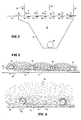
- Fig. 3 is an enlarged view of a portion of Fig. 2 showing the electrical field generated by charged rods 36 to 39 in predeterminedly spaced relationship above web 12.
- the field strength between the rods is increased to the algebraic sum of the voltages established in each rod.
- the on-site voltage available for these rods has an effect in selecting longitudinal spacing, i.e. along the mat-forming direction. Higher voltages permit greater longitudinal spacing between the rods.
- the electric field includes lines of force extending substantially horizontally between the rods.
- electric field lines of force extend parallel to the mat forming surface in the forming direction.
- electric field lines of force arch slightly, as indicated while maintaining alignment with the forming direction with a major component of the lines of force in parallel relation to the mat-forming surface.
- Fig. 4 is an enlarged view of a portion of Fig. 2.
- Mat-forming surface 60 is presented by the mat 62 being formed on web 12; next adjacent rods 36 and 37 are of opposite polarity with rod 36 being positive and rod 37 being negative.
- Fibres descend from upper portions of the flow-through chamber 24 along a flow path which is substantially normal to the web 12.
- the fibres are. randomly oriented with axes of individual fibres in any of three dimensions; that is, individual fibres may be descending with their longitudinal axes at any angle between substantially normal to the plane of the web or substantially parallel to the plane of the web and also with their longitudinal axes at any angle between alignment with the direction of movement of the mat and 90° to that direction.
- Fibres which are attracted to and adhere to the electrically charged rods are radially disposed in spoke-like fashion about each rod. This disposition of fibres adhering to the rods can be extended in length.
- Such fibre “whiskers” include fibres adhering to and extending longitudinally from a first tier of fibres in contact with the rods. As the rods rotate, in the direction shown, through the upper quadrants and through the quadrant approaching the mat-forming surface, these spoke-like protrusions of fibres become extended in length and closely adjacent. As the rotating rods take these adhering fibres through the final quadrant approaching the web 12, the fibres contact the mat-forming surface 60.
- the direction of rod rotation is such that a rod and its adhering fibres, appear to "climb" the mat as it moves in the direction shown.
- the rods are positioned so that the bottom peripheral surface of each rod is contiguous to the surface of the mat being formed; because of attraction to the energized rods, the web 12 may be lifted slightly as it travels under a rod.
- the contiguous relationship clears fibres from the rods so that a portion of the first quadrant of a rod, after passage of its closest point to the mat surface, is initially free of fibres.
- the speed of rotation of the rods is selected to maximize orientation and avoid any build-up of fibres on the rods.
- fibres falling towards and between the rods are subjected to the electric field generated by the rods, tending to orient fibres with their axes substantially parallel to the plane of the mat being formed and with their longitudinal axes in substantially the same direction as the direction of movement of web 12; such orientation is represented by the fibres in portion 66 of the chamber structure 24.
- the subsurface electrical means, bars 44 to 49 as shown in Fig. 2, help maintain a separate electric force in the mat being formed by establishing a slight current in the mat.
- a support frame 70 extends in the machine forming direction along opposite sides of the forming chamber 24.
- Support frame 70 holds the mounting and electrical contact bearings, e.g. 74, 75 at the leading ends and 76, 77 at the trailing end, for the axles 78, 79 and 80, 81, respectively, of the rods.
- the spacing between the web 12 and the rod axes increases in the direction of movement of web 12.
- Drive means 84 provides for controlled rotation of the rods.
- Additional features which can be utilized to enhance fibre orientation at increased production rates while maintaining consistent results include: maximizing the electrostatic field strength while avoiding arcing, providing for maximizing the effect of the field strength including monitoring moisture content of the fibres and addition of materials to affect physical properties of the fibres, such as electrical conductivity, selection of the quantity, type, and state of binder resin included in the furnish, control of speed of rotation and size of the electrically conductive rods for producing the electric field, and control of the longitudinal movement of the conveyor support belt for the mat being formed.
- the invention finds special application in working with lightweight fibrous materials.
- the pressure-refined wood furnish on which data is presented below had presented special problems to the prior art in obtaining desired orientation and commercial production rates.
- the wood is broken down closer to individual fibres in a pressurized steam refiner than under atmospheric attrition mill conditions.
- Various refining processes for preparing lightweight fibrous furnishes are known in the art (see e.g. "Modern Particleboard and Dry Process Fibreboard" by Thomas M. Maloney, pp. 98, 99, 212).
- a predominant part of the bulk of pressurized steam refined wood furnish comprises extremely fine, hair-like fibres which can be less than 0.0254 mm (one mil) in diameter. These hair-like fibres can vary in length up to a much as 19 mm (three- fourths inch) but are predominantly about 6.35 to about 12.7 mm (one-quarter to one-half inch) in length.
- a significant percentage by weight of such pressurized disc refined furnish comprises heavier, elongated splinter-like pieces of wood having diameters up to about 0.0508 mm (two mils). Some of these exhibit fibre-like qualities being longitudinally pliable while others are more rigid. The balance of the weight of such furnish comprises dust-like particles.
- Field strengths established by the rotating rods exhibiting voltage gradients of 101 to 404 volts per millimetre (2,500 to 10,000 volts/inch) provide suitable orientation conditions (the voltage gradient in volts per millimetre is equal to the positive polarity voltage at any instant supplied to an electrode plus the negative polarity voltage supplied at that instant to an adjacent electrode divided by the distance in millimetres between the electrodes).
- the voltage supply can be conventional; while AC or DC can be operational, DC is preferred because of better fibre orientation results.
- the voltage gradient should stay below the point where arcing can take place.
- the voltage gradient where arcing can take place in air varies from about 473 to about 670 volts per millimetre (12,000 to 17,000 volts/inch) depending on the relative humidity. Also current leakage increases more rapidly at field strengths above 404 volts per mm.
- a typical voltage gradient when working with lightweight furnish is about 315 volts per millimetre (8,000 volts/inch).
- Control of rod spacing along the machine forming direction of the electrically charged rods above the web is partially dependent on the high voltage power supply connections.
- the field strength can be increased by utilizing two voltage power supplies of opposite polarity connected to adjacent rods. With 50,000 volt D.C. power supplies and 216 mm (eight and one-half inches) spacing between the rods in the machine forming direction, a voltage gradient up to about 473 volts per millimetre can be achieved.
- the voltage output of the power supply is adjustable. With lower voltage output capability, the spacing between the rods can be reduced to maintain the desired voltage gradients. Orientation ratio increases gradually in a substantially linear fashion as the voltage gradient increases.
- rod diameter of about 19 mm provides optimum orientation results.
- Smaller or larger diameter rods e.g. from about 12.7 mm, can be used.
- rods of 31.8 mm (one and one-quarter inches) diameter and larger can result in lower orientation ratios with the lightweight wood furnish described.
- the nature of the rod metallurgy has little effect as long as the rod is a good conductor.
- Rod rotation, with the lightweight furnish described is controlled in the range of about 100 to 300 r.p.m.
- improved orientation ratios and production rates are made available over a significantly wider range of moisture contents of the lightweight pressure refined furnish than what was previously considered practical with planar electrodes of the wall and partition type.
- improved orientation ratios are available with moisture contents from about 5% to about 15% by weight. This significantly increases permissive selectivity available in the furnish and in the resin binder system used while maintaining consistency of results.
- the range of moisture contents of the furnish which could be used was more restricted; little orientation effect could be produced when the moisture content varied below an optimum percentage; e.g. 15% or higher moisture contents were generally considered to be better suited for obtaining orientation.
- moisture contents in the range of about 7-1/2% to about 10% are preferred although desired orientation ratios can be achieved over a much wider range of moisture contents. It has been found, however, that as moisture content approaches 20%, adhesiveness or so-called "tack-level" of certain resins can interfere with proper mat formation.
- Moisture content of the furnish using conventional measuring means, can be monitored for better selection of electric field strength.
- Moisture content monitoring means can be mounted along the furnish handling line to activate a water spray solenoid valve to hold moisture content during periods when very low moisture content is exhibited by the particular furnish.
- Resin types include urea formaldehyde, phenol formaldehyde, isocyanate, and tannin formaldehyde.
- the resins can be applied in powder or liquid form. Percent of resin may typically run from about 4% to about 10% by weight of the dry fibre depending on the application and the product. Some liquid resins, such as urea formaldehyde, may cause tack and consequent clumping or balling of the fibres. Lower tack resins can be selected to avoid problems which could interfere with proper alignment and uniform deposition.
- the effect of the electric field on the furnish can be modified, e.g. by controllably adding a salt, which enhances conductivity, to the fibrous material in order to improve orientation ratios.
- a salt such as sodium chloride
- inclusion of a salt, such as sodium chloride is beneficial.
- the moisture content preferred in the particular fibreboard manufacturing process provides adequate conductivity for desired orientation when using the method of the present invention.
- the ratio of particles in the "X" direction (direction of forming) to the number of particles in the "Y" direction (perpendicularly transverse to the direction of forming) is one to one.
- the index of the degree of orientation achieved with fibres is _ based on the ratio of the modulus of elasticity in the cross machine forming direction (E x ) to the modulus of elasticity in the cross machine direction (Ey).
- Ratios (E xl Ey) of 1.2:1 and higher are achieved through use of the method of the present invention with pressure-refined wood furnish which has been considered the most difficult to handle of the lightweight furnishes described.
- the present invention is capable of providing desired orientation ratios with the lightweight furnish, produced by pressurized refining, at economically acceptable production rates over commercially practical forming areas.
- desired orientation ratios For example at an 8170 kg per hour (18,000 Ibs per hour) flow rate of furnish, electric field fibre orientation to desired ratios can readily be achieved when depositing fibres from 0.081 to about 0.407 kg m- 2 s -1 (one to above five Ibs per square foot per minute) over a deposition surface of about 6.96 m 2 (seventy-five square feet).
- fibreboard having 801 kg m- 3 (fifty Ib per cubic foot) density and a 3.18 mm (one-eighth inch) thickness after curing can be formed with desired orientation ratios at the rate of 0.254 m S - 1 (fifty linear feet per minute).
- desired orientation ratios at the rate of 0.254 m S - 1 (fifty linear feet per minute).
- the final thickness desired is 6.35 mm (one-fourth inch)
- such fibreboard can be produced at 0.127 m S - 1 (twenty-five linear feet per minute).
- the actual deposition rate of the dry fibre exceeds such figures since pre-cured deposition of furnish will ordinarily be in excess of press capacity.
- the furnish is provided, distributed, oriented, and deposited at an optimum rate and, where the deposition exceeds press capacity, a portion of the mat can be shaved off prior to entry into the curing press and returned to the furnish supply and distribution line.
Landscapes
- Life Sciences & Earth Sciences (AREA)
- Engineering & Computer Science (AREA)
- Manufacturing & Machinery (AREA)
- Wood Science & Technology (AREA)
- Forests & Forestry (AREA)
- Dry Formation Of Fiberboard And The Like (AREA)
Claims (8)
Priority Applications (2)
| Application Number | Priority Date | Filing Date | Title |
|---|---|---|---|
| EP19800304611 EP0054586B1 (de) | 1980-12-19 | 1980-12-19 | Verfahren und Vorrichtung zum Ausrichten und Ablagern der Fasern bei der Faserplattenherstellung |
| DE8080304611T DE3070631D1 (en) | 1980-12-19 | 1980-12-19 | Method and apparatus for orientation and deposition of fibres in the manufacture of fibreboard |
Applications Claiming Priority (1)
| Application Number | Priority Date | Filing Date | Title |
|---|---|---|---|
| EP19800304611 EP0054586B1 (de) | 1980-12-19 | 1980-12-19 | Verfahren und Vorrichtung zum Ausrichten und Ablagern der Fasern bei der Faserplattenherstellung |
Publications (2)
| Publication Number | Publication Date |
|---|---|
| EP0054586A1 EP0054586A1 (de) | 1982-06-30 |
| EP0054586B1 true EP0054586B1 (de) | 1985-05-08 |
Family
ID=8187334
Family Applications (1)
| Application Number | Title | Priority Date | Filing Date |
|---|---|---|---|
| EP19800304611 Expired EP0054586B1 (de) | 1980-12-19 | 1980-12-19 | Verfahren und Vorrichtung zum Ausrichten und Ablagern der Fasern bei der Faserplattenherstellung |
Country Status (2)
| Country | Link |
|---|---|
| EP (1) | EP0054586B1 (de) |
| DE (1) | DE3070631D1 (de) |
Family Cites Families (5)
| Publication number | Priority date | Publication date | Assignee | Title |
|---|---|---|---|---|
| US3954364A (en) * | 1972-06-02 | 1976-05-04 | Berol Corporation | Method and apparatus for forming boards from particles |
| US3843756A (en) * | 1972-06-02 | 1974-10-22 | Berol Corp | Method for forming boards from particles |
| US4045528A (en) * | 1973-04-25 | 1977-08-30 | Dso "Stara Planina" | Method for making laminated particleboard of oriented wood particles |
| GB1581171A (en) * | 1976-04-08 | 1980-12-10 | Bison North America Inc | Alignment plate construction for electrostatic particle orientation |
| US4113812A (en) * | 1976-12-03 | 1978-09-12 | Washington State University Research Foundation | Method of forming a composite mat of directionally oriented lignocellulosic fibrous material |
-
1980
- 1980-12-19 DE DE8080304611T patent/DE3070631D1/de not_active Expired
- 1980-12-19 EP EP19800304611 patent/EP0054586B1/de not_active Expired
Also Published As
| Publication number | Publication date |
|---|---|
| EP0054586A1 (de) | 1982-06-30 |
| DE3070631D1 (en) | 1985-06-13 |
Similar Documents
| Publication | Publication Date | Title |
|---|---|---|
| US4284595A (en) | Orientation and deposition of fibers in the manufacture of fiberboard | |
| US3843756A (en) | Method for forming boards from particles | |
| CA1053172A (en) | Layer-forming apparatus especially for particle board mats | |
| US3115431A (en) | Method and apparatus for making oriented wood particle board | |
| CN101450504B (zh) | 用定向刨片层铺装成的板坯制造木材板和该板坯的制造方法、散射头以及设备 | |
| CN1078530C (zh) | 在纸上投布颗粒的装置和给纸提供颗粒的方法 | |
| US4469216A (en) | Multiple funnel flake aligner for making a loosely felted mat of aligned wood flakes | |
| US2373500A (en) | Method and apparatus for making felted materials | |
| US2187624A (en) | Apparatus for the manufacture of coated webs | |
| US4113812A (en) | Method of forming a composite mat of directionally oriented lignocellulosic fibrous material | |
| CN101259633B (zh) | 中密度纤维板真空机械铺装机 | |
| US4432916A (en) | Method and apparatus for the electrostatic orientation of particulate materials | |
| CN1168585C (zh) | 结构件用的坯料及其制造方法和分散原料的装置 | |
| US3954364A (en) | Method and apparatus for forming boards from particles | |
| WO2005091715A2 (en) | Improved pre-impregnated materials and apparatus and methods for manufacture thereof | |
| CN1199665A (zh) | 制造结构件坯料的方法和装置 | |
| CN102883862B (zh) | 在生产木质复合板的过程中用于生产由至少一个定向散布层制成的散布材料垫的方法和散布头 | |
| EP0054586B1 (de) | Verfahren und Vorrichtung zum Ausrichten und Ablagern der Fasern bei der Faserplattenherstellung | |
| US4347202A (en) | Method for production of directionally oriented lignocellulosic products, including means for cross-machine orientation | |
| US2746096A (en) | Felting apparatus | |
| US4287140A (en) | Method for orientation and deposition of lignocellulosic material in the manufacture of pressed comminuted products having directional properties | |
| CA1145108A (en) | Orientation and deposition of fibers in the manufacture of fiberboard | |
| US2284739A (en) | Manufacture of abrasive materials | |
| CN107160531B (zh) | 一种高强度纤维板的制备方法及其铺装装置 | |
| EP1069976B1 (de) | Gerät zum ausbreiten und verteilen von teilchen auf einem materialband |
Legal Events
| Date | Code | Title | Description |
|---|---|---|---|
| PUAI | Public reference made under article 153(3) epc to a published international application that has entered the european phase |
Free format text: ORIGINAL CODE: 0009012 |
|
| AK | Designated contracting states |
Designated state(s): DE GB IT SE |
|
| RBV | Designated contracting states (corrected) |
Designated state(s): DE GB IT SE |
|
| 17P | Request for examination filed |
Effective date: 19821207 |
|
| GRAA | (expected) grant |
Free format text: ORIGINAL CODE: 0009210 |
|
| AK | Designated contracting states |
Designated state(s): DE GB IT SE |
|
| PG25 | Lapsed in a contracting state [announced via postgrant information from national office to epo] |
Ref country code: IT Free format text: LAPSE BECAUSE OF FAILURE TO SUBMIT A TRANSLATION OF THE DESCRIPTION OR TO PAY THE FEE WITHIN THE PRESCRIBED TIME-LIMIT;WARNING: LAPSES OF ITALIAN PATENTS WITH EFFECTIVE DATE BEFORE 2007 MAY HAVE OCCURRED AT ANY TIME BEFORE 2007. THE CORRECT EFFECTIVE DATE MAY BE DIFFERENT FROM THE ONE RECORDED. Effective date: 19850508 |
|
| REF | Corresponds to: |
Ref document number: 3070631 Country of ref document: DE Date of ref document: 19850613 |
|
| PLBE | No opposition filed within time limit |
Free format text: ORIGINAL CODE: 0009261 |
|
| STAA | Information on the status of an ep patent application or granted ep patent |
Free format text: STATUS: NO OPPOSITION FILED WITHIN TIME LIMIT |
|
| 26N | No opposition filed | ||
| GBPC | Gb: european patent ceased through non-payment of renewal fee | ||
| PG25 | Lapsed in a contracting state [announced via postgrant information from national office to epo] |
Ref country code: GB Effective date: 19881121 |
|
| PGFP | Annual fee paid to national office [announced via postgrant information from national office to epo] |
Ref country code: SE Payment date: 19921116 Year of fee payment: 13 |
|
| PGFP | Annual fee paid to national office [announced via postgrant information from national office to epo] |
Ref country code: DE Payment date: 19921123 Year of fee payment: 13 |
|
| PG25 | Lapsed in a contracting state [announced via postgrant information from national office to epo] |
Ref country code: SE Effective date: 19931220 |
|
| PG25 | Lapsed in a contracting state [announced via postgrant information from national office to epo] |
Ref country code: DE Effective date: 19940901 |
|
| EUG | Se: european patent has lapsed |
Ref document number: 80304611.9 Effective date: 19940710 |