EP0054579B1 - Battery assemblage - Google Patents
Battery assemblage Download PDFInfo
- Publication number
- EP0054579B1 EP0054579B1 EP80108064A EP80108064A EP0054579B1 EP 0054579 B1 EP0054579 B1 EP 0054579B1 EP 80108064 A EP80108064 A EP 80108064A EP 80108064 A EP80108064 A EP 80108064A EP 0054579 B1 EP0054579 B1 EP 0054579B1
- Authority
- EP
- European Patent Office
- Prior art keywords
- battery
- cells
- connectors
- cell
- assemblage
- Prior art date
- Legal status (The legal status is an assumption and is not a legal conclusion. Google has not performed a legal analysis and makes no representation as to the accuracy of the status listed.)
- Expired
Links
- 230000008878 coupling Effects 0.000 claims abstract description 14
- 238000010168 coupling process Methods 0.000 claims abstract description 14
- 238000005859 coupling reaction Methods 0.000 claims abstract description 14
- 230000001012 protector Effects 0.000 claims abstract description 13
- 239000002184 metal Substances 0.000 claims abstract description 11
- 239000007788 liquid Substances 0.000 claims abstract description 3
- 210000002105 tongue Anatomy 0.000 claims description 4
- 238000004519 manufacturing process Methods 0.000 description 5
- 238000005266 casting Methods 0.000 description 2
- 238000003908 quality control method Methods 0.000 description 2
- 230000002950 deficient Effects 0.000 description 1
- 230000003467 diminishing effect Effects 0.000 description 1
- 239000012530 fluid Substances 0.000 description 1
- 238000000926 separation method Methods 0.000 description 1
Images



Classifications
-
- H—ELECTRICITY
- H01—ELECTRIC ELEMENTS
- H01M—PROCESSES OR MEANS, e.g. BATTERIES, FOR THE DIRECT CONVERSION OF CHEMICAL ENERGY INTO ELECTRICAL ENERGY
- H01M50/00—Constructional details or processes of manufacture of the non-active parts of electrochemical cells other than fuel cells, e.g. hybrid cells
- H01M50/20—Mountings; Secondary casings or frames; Racks, modules or packs; Suspension devices; Shock absorbers; Transport or carrying devices; Holders
- H01M50/258—Modular batteries; Casings provided with means for assembling
-
- H—ELECTRICITY
- H01—ELECTRIC ELEMENTS
- H01M—PROCESSES OR MEANS, e.g. BATTERIES, FOR THE DIRECT CONVERSION OF CHEMICAL ENERGY INTO ELECTRICAL ENERGY
- H01M50/00—Constructional details or processes of manufacture of the non-active parts of electrochemical cells other than fuel cells, e.g. hybrid cells
- H01M50/20—Mountings; Secondary casings or frames; Racks, modules or packs; Suspension devices; Shock absorbers; Transport or carrying devices; Holders
- H01M50/204—Racks, modules or packs for multiple batteries or multiple cells
- H01M50/207—Racks, modules or packs for multiple batteries or multiple cells characterised by their shape
- H01M50/209—Racks, modules or packs for multiple batteries or multiple cells characterised by their shape adapted for prismatic or rectangular cells
-
- H—ELECTRICITY
- H01—ELECTRIC ELEMENTS
- H01M—PROCESSES OR MEANS, e.g. BATTERIES, FOR THE DIRECT CONVERSION OF CHEMICAL ENERGY INTO ELECTRICAL ENERGY
- H01M50/00—Constructional details or processes of manufacture of the non-active parts of electrochemical cells other than fuel cells, e.g. hybrid cells
- H01M50/50—Current conducting connections for cells or batteries
- H01M50/502—Interconnectors for connecting terminals of adjacent batteries; Interconnectors for connecting cells outside a battery casing
- H01M50/503—Interconnectors for connecting terminals of adjacent batteries; Interconnectors for connecting cells outside a battery casing characterised by the shape of the interconnectors
-
- H—ELECTRICITY
- H01—ELECTRIC ELEMENTS
- H01M—PROCESSES OR MEANS, e.g. BATTERIES, FOR THE DIRECT CONVERSION OF CHEMICAL ENERGY INTO ELECTRICAL ENERGY
- H01M50/00—Constructional details or processes of manufacture of the non-active parts of electrochemical cells other than fuel cells, e.g. hybrid cells
- H01M50/50—Current conducting connections for cells or batteries
- H01M50/502—Interconnectors for connecting terminals of adjacent batteries; Interconnectors for connecting cells outside a battery casing
- H01M50/514—Methods for interconnecting adjacent batteries or cells
- H01M50/517—Methods for interconnecting adjacent batteries or cells by fixing means, e.g. screws, rivets or bolts
-
- H—ELECTRICITY
- H01—ELECTRIC ELEMENTS
- H01M—PROCESSES OR MEANS, e.g. BATTERIES, FOR THE DIRECT CONVERSION OF CHEMICAL ENERGY INTO ELECTRICAL ENERGY
- H01M50/00—Constructional details or processes of manufacture of the non-active parts of electrochemical cells other than fuel cells, e.g. hybrid cells
- H01M50/50—Current conducting connections for cells or batteries
- H01M50/502—Interconnectors for connecting terminals of adjacent batteries; Interconnectors for connecting cells outside a battery casing
- H01M50/521—Interconnectors for connecting terminals of adjacent batteries; Interconnectors for connecting cells outside a battery casing characterised by the material
- H01M50/522—Inorganic material
-
- Y—GENERAL TAGGING OF NEW TECHNOLOGICAL DEVELOPMENTS; GENERAL TAGGING OF CROSS-SECTIONAL TECHNOLOGIES SPANNING OVER SEVERAL SECTIONS OF THE IPC; TECHNICAL SUBJECTS COVERED BY FORMER USPC CROSS-REFERENCE ART COLLECTIONS [XRACs] AND DIGESTS
- Y02—TECHNOLOGIES OR APPLICATIONS FOR MITIGATION OR ADAPTATION AGAINST CLIMATE CHANGE
- Y02E—REDUCTION OF GREENHOUSE GAS [GHG] EMISSIONS, RELATED TO ENERGY GENERATION, TRANSMISSION OR DISTRIBUTION
- Y02E60/00—Enabling technologies; Technologies with a potential or indirect contribution to GHG emissions mitigation
- Y02E60/10—Energy storage using batteries
Definitions
- This invention is concerned with a battery assemblage, in particular with a casing for modular batteries.
- the above mentioned problems have been solved by the provision of batteries constituted by an assemblage of rigidly interconnectable separate cells as disclosed in documents (1) to (4), such assemblages having the advantages specified on page 4.
- the present invention relates to an assemblage of such type.
- the battery assemblage of this invention comprises a series of removable and coupling elements, rigidly interengaged by means of a combination of head couplings in vertical and horizontal orientations, the battery further consisting of:
- the cell carries ribs of variable width inside, with the wider rib having the female head coupling, progressively diminishing until it reaches the narrowest portion at the end where the male head coupling is located.
- the metal connectors which electrically join the terminals are provided with projecting tongues engaging the slots of protectors when constructed over the same.
- the long protector has round holes at its ends.
- the battery consists of two assembled pieces, removable and intercoupling, which are as follows:
- These corrective plates have a projecting flange around their periphery for engaging ribs in corresponding slots therein when the battery is assembled.
Landscapes
- Chemical & Material Sciences (AREA)
- Chemical Kinetics & Catalysis (AREA)
- Electrochemistry (AREA)
- General Chemical & Material Sciences (AREA)
- Inorganic Chemistry (AREA)
- Connection Of Batteries Or Terminals (AREA)
- Battery Mounting, Suspending (AREA)
- Primary Cells (AREA)
Abstract
Description
- This invention is concerned with a battery assemblage, in particular with a casing for modular batteries.
- It is well known, that in this century there has been a great deal of research work concerning a way to store electric energy for subsequent use within generally small units.
- There are four (4) documents which relate to batteries formed from interlocking cells connected by dove-tail ribs, and which I consider relevant for this application (1) NL-A-6 906 053; (2) GB-A-840 476; (3) US-A-3 338 452; (4) GB-A-743 215.
- The classic way has been in general, a one piece battery for 6 to 12 volts with two terminals. Because it is a one piece unit, this battery has several problems, for example: i) When only one cell is broken down, it is necessary to replace the whole unit, since repair is difficult and expensive. ii) A high percentage of these batteries are lost due to quality control at the manufacturing plants, since during the manufacturing process one of the cells that make up the battery is likely to fail and not work properly. iii) Casting molds for the manufacture of casings are very expensive.
- The above mentioned problems have been solved by the provision of batteries constituted by an assemblage of rigidly interconnectable separate cells as disclosed in documents (1) to (4), such assemblages having the advantages specified on page 4. The present invention relates to an assemblage of such type.
- The battery assemblage of this invention comprises a series of removable and coupling elements, rigidly interengaged by means of a combination of head couplings in vertical and horizontal orientations, the battery further consisting of:
- a) cells or receptacles, with male and female head couplings at their corners, extending vertically along the length of each cell;
- b) two metal terminals projecting from each cell at the top extremes of its cover, with a central opening for receiving electrolytic liquids;
- c) metal connectors, electrically connecting two adjacent cells by means of threaded screws;
- d) two protectors, one long and one short in "U" shape in order to cover two rows of connectors of the assembled battery, functioning as coupling heads in horizontal orientation, said protectors also having slots which engage with the projecting tongues of the connectors, in order to provide rigid interengagement of the cells in the horizontal orientation.
- Preferably the cell carries ribs of variable width inside, with the wider rib having the female head coupling, progressively diminishing until it reaches the narrowest portion at the end where the male head coupling is located. The metal connectors which electrically join the terminals are provided with projecting tongues engaging the slots of protectors when constructed over the same. Suitably the long protector has round holes at its ends.
- In one embodiment of the present invention, the battery consists of two assembled pieces, removable and intercoupling, which are as follows:
- Cells or recptacles containing electrolytic fluid and lead plates, either low or high, with capacity for supplying 2 volts. In their corners, each cell has male and female dovetail couplings, anti- metrically opposed, carried vertically along the length of the cell, in order to obtain proper orientation of the cell for connecting electrical terminals either in series or in parallel. Furthermore, dovetail couplings provide good rigidity to the battery due to their length.
- There are ribs disposed within the cells for adequate separation and adjustment of lead plates, whereby said plates may be placed diagonally in relation to the cell, making the most use of the space available without enlarging the dimensions of standard conventional batteries. Metal connections join electrically projecting terminals of two adjacent cells by means of threaded screws axially introduced in terminals, allowing ease for replacement of any cell not working properly.
- These corrective plates have a projecting flange around their periphery for engaging ribs in corresponding slots therein when the battery is assembled.
- Protectors in "U" form for covering the battery connectors when assembled, also function as head couplings in horizontal orientation for better rigidity of the whole.
- The longest of these protectors projects somewhat from the battery with round holes at its ends for fixing the battery in place on its base.
- This new battery has better rigidity of the whole in addition to the advantages common to batteries assembled from separate cells such as:
- - Any desired voltage may be obtained, simply by adding several cells either in series or in parallel.
- - The assembled battery for 6 or for 12 volts has standard dimensions for conventional cars.
- - Quality control becomes simpler, since it is performed on each one of the cells, so that only those in good conditions reach the final battery.
- - Under normal conditions of use, any defective cell may be replaced without changing the whole battery.
- - Casting molds for cell manufacture are much cheaper than those used for the manufacture of conventional batteries.
-
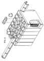
- Figure 1 is a perspective view of 12-volt Battery formed by the connection of 6 2-volt separate cells, without protectors.
- Figure 2 is a perspective view of 12-volt Battery formed by the connection of 6 2-volt separate cells with protectors.
- Figure 3 is a perspective view of 12-volt Battery formed by the connection of 6 2-volt separate cells, showing placement of protectors, metal connectors and terminals.
- Figure 4 shows Top and Front elevation views of a 2-volt cell, showing Battery caps and metal terminals.
Claims (2)
Priority Applications (3)
| Application Number | Priority Date | Filing Date | Title |
|---|---|---|---|
| DE8080108064T DE3070564D1 (en) | 1980-12-19 | 1980-12-19 | Battery assemblage |
| EP80108064A EP0054579B1 (en) | 1980-12-19 | 1980-12-19 | Battery assemblage |
| AT80108064T ATE12993T1 (en) | 1980-12-19 | 1980-12-19 | BATTERY COMPOSITION. |
Applications Claiming Priority (1)
| Application Number | Priority Date | Filing Date | Title |
|---|---|---|---|
| EP80108064A EP0054579B1 (en) | 1980-12-19 | 1980-12-19 | Battery assemblage |
Publications (2)
| Publication Number | Publication Date |
|---|---|
| EP0054579A1 EP0054579A1 (en) | 1982-06-30 |
| EP0054579B1 true EP0054579B1 (en) | 1985-04-24 |
Family
ID=8186940
Family Applications (1)
| Application Number | Title | Priority Date | Filing Date |
|---|---|---|---|
| EP80108064A Expired EP0054579B1 (en) | 1980-12-19 | 1980-12-19 | Battery assemblage |
Country Status (3)
| Country | Link |
|---|---|
| EP (1) | EP0054579B1 (en) |
| AT (1) | ATE12993T1 (en) |
| DE (1) | DE3070564D1 (en) |
Families Citing this family (7)
| Publication number | Priority date | Publication date | Assignee | Title |
|---|---|---|---|---|
| US4460663A (en) * | 1983-01-07 | 1984-07-17 | Sab Nife Ab | Battery casing construction and method of making same |
| US4957829A (en) * | 1989-06-26 | 1990-09-18 | At&T Bell Laboratories | Modular battery plant system assembly comprising multiple unit cell modules |
| US5236792A (en) * | 1991-08-29 | 1993-08-17 | At&T Bell Laboratories | Batteries and components |
| US5578392A (en) * | 1995-02-17 | 1996-11-26 | Japan Storage Battery Co., Ltd. | Cylindrical cell, a cell pack, and a cell holder |
| ES2179734B1 (en) * | 2000-06-13 | 2004-04-01 | SOCIEDAD ESPAñOLA DEL ACUMULADOR TUDOR, S.A. | BATTERIES OF ELECTRIC ACCUMULATORS. |
| ES2193849B1 (en) * | 2001-07-31 | 2005-03-01 | S.E. Acumulador Tudor, S.A. | BATTERY OF ELECTRIC ACCUMULATORS. |
| CN100479254C (en) * | 2007-03-27 | 2009-04-15 | 中山中炬森莱高技术有限公司 | Battery pack for electric vehicle and manufacturing method thereof |
Citations (7)
| Publication number | Priority date | Publication date | Assignee | Title |
|---|---|---|---|---|
| GB840476A (en) * | 1958-01-06 | 1960-07-06 | Leonard Charles Pedder | Improvements in or relating to electric batteries |
| FR1337256A (en) * | 1962-05-24 | 1963-09-13 | Wonder Piles | Flat battery connection box |
| US3338452A (en) * | 1964-11-23 | 1967-08-29 | Michael J Oakley | Case for storage battery cell |
| NL6906053A (en) * | 1969-02-04 | 1970-08-06 | ||
| FR2058740A5 (en) * | 1969-09-23 | 1971-05-28 | Accumulateurs Fixes | |
| DE2136749A1 (en) * | 1971-07-22 | 1973-02-01 | Stadelmayr Hans G | BATTERY PROTECTIVE DEVICE |
| FR2156642A1 (en) * | 1971-10-15 | 1973-06-01 | Bosch |
Family Cites Families (1)
| Publication number | Priority date | Publication date | Assignee | Title |
|---|---|---|---|---|
| BE519506A (en) * | 1952-04-26 |
-
1980
- 1980-12-19 AT AT80108064T patent/ATE12993T1/en not_active IP Right Cessation
- 1980-12-19 EP EP80108064A patent/EP0054579B1/en not_active Expired
- 1980-12-19 DE DE8080108064T patent/DE3070564D1/en not_active Expired
Patent Citations (7)
| Publication number | Priority date | Publication date | Assignee | Title |
|---|---|---|---|---|
| GB840476A (en) * | 1958-01-06 | 1960-07-06 | Leonard Charles Pedder | Improvements in or relating to electric batteries |
| FR1337256A (en) * | 1962-05-24 | 1963-09-13 | Wonder Piles | Flat battery connection box |
| US3338452A (en) * | 1964-11-23 | 1967-08-29 | Michael J Oakley | Case for storage battery cell |
| NL6906053A (en) * | 1969-02-04 | 1970-08-06 | ||
| FR2058740A5 (en) * | 1969-09-23 | 1971-05-28 | Accumulateurs Fixes | |
| DE2136749A1 (en) * | 1971-07-22 | 1973-02-01 | Stadelmayr Hans G | BATTERY PROTECTIVE DEVICE |
| FR2156642A1 (en) * | 1971-10-15 | 1973-06-01 | Bosch |
Also Published As
| Publication number | Publication date |
|---|---|
| ATE12993T1 (en) | 1985-05-15 |
| EP0054579A1 (en) | 1982-06-30 |
| DE3070564D1 (en) | 1985-05-30 |
Similar Documents
| Publication | Publication Date | Title |
|---|---|---|
| US4347294A (en) | Novel electric storage battery assembly | |
| DE102017212941B4 (en) | Battery pack | |
| US3941615A (en) | Battery construction | |
| US4022951A (en) | Battery construction | |
| EP0054579B1 (en) | Battery assemblage | |
| US3388007A (en) | Thin wall polypropylene battery case | |
| JPH0334271A (en) | Battery plant system | |
| US4424264A (en) | Multicell electric storage batteries | |
| US9472794B1 (en) | Battery module housing assembly | |
| US2702310A (en) | Battery construction | |
| US3147151A (en) | Electric storage battery and casing | |
| KR102321969B1 (en) | A Cell Case Structure for cylindrical battery Cells | |
| US5432019A (en) | System for the electrical power supply of a vehicle | |
| US1907420A (en) | Battery construction | |
| US2132793A (en) | Storage battery construction | |
| CN215771338U (en) | Battery module and battery pack | |
| DE3734221A1 (en) | METHOD FOR AVOIDING OVERHEATING OF HIGH TEMPERATURE BATTERIES | |
| US2692906A (en) | Storage battery | |
| EP0167400B1 (en) | Separator plate for lead-acid battery | |
| AU774019B2 (en) | The improved combining structure between the battery electrode plates and the battery case | |
| CN210576063U (en) | Lithium battery device for AGV | |
| US3746579A (en) | Battery having container in two portions and a method for making it | |
| CA1122272A (en) | Producing individual battery connectors in situ by severing of composite connector | |
| DE60010908T2 (en) | FLAT BLEIAKUMULATOR WITH FRONT LATCH POLKLEMME | |
| DE102023110895A1 (en) | BATTERY COMPARTMENT, BATTERY PACK AND ELECTRICAL CONSUMER |
Legal Events
| Date | Code | Title | Description |
|---|---|---|---|
| PUAI | Public reference made under article 153(3) epc to a published international application that has entered the european phase |
Free format text: ORIGINAL CODE: 0009012 |
|
| 17P | Request for examination filed |
Effective date: 19811126 |
|
| AK | Designated contracting states |
Designated state(s): AT BE CH DE FR GB IT LU NL SE |
|
| ITF | It: translation for a ep patent filed | ||
| GRAA | (expected) grant |
Free format text: ORIGINAL CODE: 0009210 |
|
| AK | Designated contracting states |
Designated state(s): AT BE CH DE FR GB IT LI LU NL SE |
|
| REF | Corresponds to: |
Ref document number: 12993 Country of ref document: AT Date of ref document: 19850515 Kind code of ref document: T |
|
| REF | Corresponds to: |
Ref document number: 3070564 Country of ref document: DE Date of ref document: 19850530 |
|
| ET | Fr: translation filed | ||
| PG25 | Lapsed in a contracting state [announced via postgrant information from national office to epo] |
Ref country code: LU Free format text: LAPSE BECAUSE OF NON-PAYMENT OF DUE FEES Effective date: 19851231 |
|
| PLBE | No opposition filed within time limit |
Free format text: ORIGINAL CODE: 0009261 |
|
| STAA | Information on the status of an ep patent application or granted ep patent |
Free format text: STATUS: NO OPPOSITION FILED WITHIN TIME LIMIT |
|
| 26N | No opposition filed | ||
| PGFP | Annual fee paid to national office [announced via postgrant information from national office to epo] |
Ref country code: AT Payment date: 19861212 Year of fee payment: 7 |
|
| PGFP | Annual fee paid to national office [announced via postgrant information from national office to epo] |
Ref country code: NL Payment date: 19861231 Year of fee payment: 7 |
|
| PG25 | Lapsed in a contracting state [announced via postgrant information from national office to epo] |
Ref country code: AT Effective date: 19871219 |
|
| PG25 | Lapsed in a contracting state [announced via postgrant information from national office to epo] |
Ref country code: SE Effective date: 19871220 |
|
| PG25 | Lapsed in a contracting state [announced via postgrant information from national office to epo] |
Ref country code: LI Effective date: 19871231 Ref country code: CH Effective date: 19871231 Ref country code: BE Effective date: 19871231 |
|
| BERE | Be: lapsed |
Owner name: MEJIA-ARANGO SANTIAGO Effective date: 19871231 |
|
| PG25 | Lapsed in a contracting state [announced via postgrant information from national office to epo] |
Ref country code: NL Effective date: 19880701 |
|
| NLV4 | Nl: lapsed or anulled due to non-payment of the annual fee | ||
| REG | Reference to a national code |
Ref country code: CH Ref legal event code: PL |
|
| ITTA | It: last paid annual fee | ||
| PGFP | Annual fee paid to national office [announced via postgrant information from national office to epo] |
Ref country code: GB Payment date: 19911217 Year of fee payment: 12 |
|
| PGFP | Annual fee paid to national office [announced via postgrant information from national office to epo] |
Ref country code: FR Payment date: 19911230 Year of fee payment: 12 Ref country code: DE Payment date: 19911230 Year of fee payment: 12 |
|
| PG25 | Lapsed in a contracting state [announced via postgrant information from national office to epo] |
Ref country code: GB Effective date: 19921219 |
|
| GBPC | Gb: european patent ceased through non-payment of renewal fee |
Effective date: 19921219 |
|
| PG25 | Lapsed in a contracting state [announced via postgrant information from national office to epo] |
Ref country code: FR Effective date: 19930831 |
|
| PG25 | Lapsed in a contracting state [announced via postgrant information from national office to epo] |
Ref country code: DE Effective date: 19930901 |
|
| REG | Reference to a national code |
Ref country code: FR Ref legal event code: ST |
|
| EUG | Se: european patent has lapsed |
Ref document number: 80108064.9 Effective date: 19880912 |