EP0054446A1 - Elektrischer Asynchronmotor, Einrichtung zum Regeln der Speisung eines solchen Motors und Umwälzantrieb mit einem solchen Motor - Google Patents
Elektrischer Asynchronmotor, Einrichtung zum Regeln der Speisung eines solchen Motors und Umwälzantrieb mit einem solchen Motor Download PDFInfo
- Publication number
- EP0054446A1 EP0054446A1 EP81401755A EP81401755A EP0054446A1 EP 0054446 A1 EP0054446 A1 EP 0054446A1 EP 81401755 A EP81401755 A EP 81401755A EP 81401755 A EP81401755 A EP 81401755A EP 0054446 A1 EP0054446 A1 EP 0054446A1
- Authority
- EP
- European Patent Office
- Prior art keywords
- motor
- capacitor
- power supply
- switch
- resistor
- Prior art date
- Legal status (The legal status is an assumption and is not a legal conclusion. Google has not performed a legal analysis and makes no representation as to the accuracy of the status listed.)
- Granted
Links
Images

Classifications
-
- H—ELECTRICITY
- H02—GENERATION; CONVERSION OR DISTRIBUTION OF ELECTRIC POWER
- H02P—CONTROL OR REGULATION OF ELECTRIC MOTORS, ELECTRIC GENERATORS OR DYNAMO-ELECTRIC CONVERTERS; CONTROLLING TRANSFORMERS, REACTORS OR CHOKE COILS
- H02P25/00—Arrangements or methods for the control of AC motors characterised by the kind of AC motor or by structural details
- H02P25/02—Arrangements or methods for the control of AC motors characterised by the kind of AC motor or by structural details characterised by the kind of motor
- H02P25/04—Single phase motors, e.g. capacitor motors
-
- H—ELECTRICITY
- H02—GENERATION; CONVERSION OR DISTRIBUTION OF ELECTRIC POWER
- H02P—CONTROL OR REGULATION OF ELECTRIC MOTORS, ELECTRIC GENERATORS OR DYNAMO-ELECTRIC CONVERTERS; CONTROLLING TRANSFORMERS, REACTORS OR CHOKE COILS
- H02P1/00—Arrangements for starting electric motors or dynamo-electric converters
- H02P1/16—Arrangements for starting electric motors or dynamo-electric converters for starting dynamo-electric motors or dynamo-electric converters
- H02P1/42—Arrangements for starting electric motors or dynamo-electric converters for starting dynamo-electric motors or dynamo-electric converters for starting an individual single-phase induction motor
- H02P1/44—Arrangements for starting electric motors or dynamo-electric converters for starting dynamo-electric motors or dynamo-electric converters for starting an individual single-phase induction motor by phase-splitting with a capacitor
Definitions
- the invention relates to a single-phase asyncrhone electric motor provided with an auxiliary starting winding in series with a capacitor, to a device for controlling the speed of such a motor and to a central heating installation circulator comprising a motor of this type to drive the water circulation control pump.
- the invention overcomes this drawback.
- a means is provided for acting on the conduction time. of the electronic switch of this supply as a function of the voltage across the capacitor or, of the voltage across the auxiliary winding.
- the electrical energy supplied to the motor can therefore be just that necessary for its operation and it is possible to obtain satisfactory and particularly economical regulation of the speed of the motor.
- the control circuit is such that, when the speed is below a determined threshold, means are provided for supplying the motor with maximum power for a predetermined time t, for example of the order of a few seconds, and is then supplied with the displayed power . In this way the motor is supplied with maximum power at start-up during the time t. If, when the motor is running, the speed decreases, due to the increase in the resistive torque due to the scaling of the pump, the motor is again supplied at maximum power during this time t. The power supply at maximum power removes the scale which causes the excessive increase of the resistive torque. An automatic "degumming" is thus obtained.
- the motors are intended for driving water circulation pumps in a central heating installation.
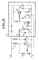
- the motor (FIG. 1) comprises a main stator winding 1, supplied with single-phase electric current by the sector thanks to two conductors 2 and 3.
- the series assembly of an auxiliary winding 4 and a capacitor is permanently arranged in parallel on the main winding, or winding 1. It is known in fact that a winding supplied with single-phase alternating current creates two magnetic fields which are opposed and therefore cannot rotate the rotor when it is stopped. It is only when the rotor begins to rotate that the field exerted on this rotor (not shown) has a non-zero effect.
- the assembly formed by the auxiliary stator winding 4 and the capacitor 5 aims, in a manner known per se, to allow the starting of the single-phase asynchronous motor by creating a rotary field resulting non-zero when the rotor is stopped.
- l main winding 1 is formed by two half-windings 6 and 7 between which a triac 8 is interposed forming the electronic switch of a switching power supply.
- a terminal of the half-winding 6 is connected directly to line 2
- the opposite terminal is connected to a terminal of the half-winding 7 via the triac 8
- the opposite terminal of this half-winding 7 is connected to the conductor 3.
- the trigger 9 of the triac is connected to the common terminal 10 to a variable resistor 11 and a capacitor 12 via a diac 13.
- the series assembly of the variable resistor 11 and the capacitor 12 is in parallel on the triac 8.
- the value of resistance 11 depends on the speed desired for the motor. It is thus possible to display any speed by choosing the value of the resistor 11.
- the assembly in parallel on the variable resistor 11, the assembly is arranged in series with a resistor 14, significantly lower in value than the resistor 11, and a controlled switch 15 such as a relay.
- the switch 15 is closed when it is desired to supply the motor at its maximum power.
- the coil 16 of this relay is placed in a circuit 17 for controlling the speed.
- circuit 17 The energy necessary for the operation of circuit 17 is obtained by rectifying the current supplied by the sector.
- the anode of a diode 18 is connected to the conductor 2 while the cathode of this diode is connected to the cathode of a Zener diode 19 is connected to the conductor 3.
- a filtering capacitor 35 is in parallel on the Zener diode 19.
- the motor speed is detected by monitoring the voltage across the capacitor 5.
- the circuit 17 therefore includes a resistor 21 connected, on one side, to the common point 22 to the winding 4 and to the capacitor 5 and on the other side at the anode of a diode 23 whose cathode is connected to the conductor 3 via a capacitor 24.
- the series assembly of a resistor 25 and a capacitor 26 is in parallel on the capacitor 24.
- a potentiometer 27 In parallel on the capacitor 26 is disposed the total resistance of a potentiometer 27 whose socket or slider 28 is connected to the base of an NPN transistor 29 whose emitter is connected to the conductor 3.
- the collector of the transistor 29 is connected to the cathode of the Zener diode 19 via a resistor 30.
- This collector is also connected to the anode of a diode 31, the cathode of which is connected to the emitter of transistor 29 via a capacitor 32 as well as at the base of another NPN transistor 33 via a resistor 34.
- One terminal of the coil 16 of the relay is connected to the cathode of the Zener diode 19 and its other terminal is connected to the collector of transistor 33, the emitter of which is connected to conductor 3.
- the capacitor 5 After starting, the capacitor 5 is charged and this charge is transmitted to the capacitors 24 and 26.
- the charge of the capacitor 26 is delayed by the presence of resistors 21 and 25.
- the potential of the cursor 28 When the capacitor 26 is charged the potential of the cursor 28 is greater than potential of the emitter of transistor 29 and it therefore becomes conductive. Under these conditions the potential of the collector of this transistor 29 and that of the anode of the diode 31 is practically equal to the potential of the conductor 3 and thus the potential of the base of the transistor 33 decreases. For this reason, the latter is blocked, possibly after discharge of the capacitor 32 through the base-emitter junction of said transistor 33. It follows that the coil 16 of the relay is no longer supplied and the switch 15 opens. The power supply, and therefore the speed, is then determined by the value of the resistor 11.
- the switch 15 is closed and the motor is powered at maximum power and, after a time t of the order of a few seconds, the switch 15 opens and the power supply then corresponds to that necessary to obtain the desired speed.
- the threshold below which the speed of rotation of the motor must fall in order for it to be supplied with its maximum power supply is determined by the position of the cursor 28 of the potentiometer 27.
- the time delay that is to say the supply of the motor at its maximum power during the time t, of the order of a few seconds, prevents too frequent tripping of relay 15 and therefore ensures satisfactory servo-control.
- an optoelectronic device can be provided.
- No resistor and switch are provided in parallel on the variable resistor ll 'but, instead, a connection 50 between the emitter of the transistor 33' and the trigger 9 'of the triac 8'.
- a resistor 51 and disposed in the connection 50 and a resistor 52 is located between the emitter of the transistor 33 'and the conductor 3'.
- the collector of transistor 33 ' is directly connected to the cathode of the Zener diode 19'.
- circuit 17 ' is the same as that of circuit 17.
- the transistor 33' is conductive when the voltage across the terminals of capacitor 5 'is below a determined threshold; the potential of the emitter of this transistor 33 'is then positive and this positive potential is transmitted to the trigger 9' of the triac 8 ', which has the consequence that the latter is permanently conductive.
- the power supply of the motor is slaved to its speed by measuring the latter using the voltage across the terminals of the auxiliary winding 4 instead of measuring the voltage across the terminals of the capacitor 5.
- the speed is measured by the interposition of a resistor in series with the main winding 1; however, this latter embodiment is less advantageous than the previous two.
- a particular advantage of the choice, for the measurement of the speed, of the voltage across the terminals of the capacitor 5 is that its terminals are generally easily accessible from the outside.
- the servo-control is of the progressive type and not of all or nothing, an error signal being supplied to the trigger of the triac (9 or 9 ') so that the speed is exactly that displayed whatever the resistive torque.
- an integrated circuit is provided such as that of reference L 120 or L 121 of the company SGS for controlling the conduction time (or ignition angle) of the thyristor 8 '.
- the speed displayed is then a DC voltage applied to the input of this integrated circuit and the error signal is obtained by comparison between this voltage and that appearing between the socket 28 'and the conductor 3'.
- the capacitors 24 and 26 and the resistors 21 and 25 then constitute an integrator avoiding sudden variations in the speed of the motor which could make it noisy.
Landscapes
- Engineering & Computer Science (AREA)
- Power Engineering (AREA)
- Control Of Ac Motors In General (AREA)
- Motor And Converter Starters (AREA)
Applications Claiming Priority (2)
| Application Number | Priority Date | Filing Date | Title |
|---|---|---|---|
| FR8026077 | 1980-12-09 | ||
| FR8026077A FR2495855A1 (fr) | 1980-12-09 | 1980-12-09 | Moteur electrique asynchrone, dispositif de commande de l'alimentation d'un tel moteur et circulateur comportant un tel moteur |
Publications (2)
| Publication Number | Publication Date |
|---|---|
| EP0054446A1 true EP0054446A1 (de) | 1982-06-23 |
| EP0054446B1 EP0054446B1 (de) | 1984-07-25 |
Family
ID=9248828
Family Applications (1)
| Application Number | Title | Priority Date | Filing Date |
|---|---|---|---|
| EP19810401755 Expired EP0054446B1 (de) | 1980-12-09 | 1981-10-30 | Elektrischer Asynchronmotor, Einrichtung zum Regeln der Speisung eines solchen Motors und Umwälzantrieb mit einem solchen Motor |
Country Status (3)
| Country | Link |
|---|---|
| EP (1) | EP0054446B1 (de) |
| DE (1) | DE3165110D1 (de) |
| FR (1) | FR2495855A1 (de) |
Cited By (6)
| Publication number | Priority date | Publication date | Assignee | Title |
|---|---|---|---|---|
| FR2608859A1 (fr) * | 1986-12-17 | 1988-06-24 | Bosch Siemens Hausgeraete | Dispositif de commande pour un moteur a induction a au moins deux enroulements de phase en tant que moteur d'entrainement d'une machine a traiter le linge |
| FR2634603A1 (fr) * | 1988-07-22 | 1990-01-26 | Option | Circuit de commande, a variateur de vitesse, d'un moteur asynchrone monophase, et module permettant la realisation d'un tel circuit de commande a partir d'un circuit de commande classique |
| EP0629037A1 (de) * | 1993-06-08 | 1994-12-14 | POMPES SALMSON Société Anonyme à directoire dite: | Verfahren und Vorrichtung zur Regelung der Stromversorgung eines Asynchronmotors |
| WO2004031778A2 (de) * | 2002-09-28 | 2004-04-15 | Stanislav Tkadlec | Drehzahlmessung/drehzahlsteuerung eines einphasigen asynchronmotors und eines universalmotors |
| WO2007089083A2 (en) | 2006-02-02 | 2007-08-09 | Lg Electronics, Inc. | Control apparatus for linear compressor |
| FR2990813A1 (fr) * | 2012-05-21 | 2013-11-22 | Atlantic Industrie Sas | Circuit d'alimentation de moteur asynchrone |
Citations (3)
| Publication number | Priority date | Publication date | Assignee | Title |
|---|---|---|---|---|
| FR2042259A5 (de) * | 1969-04-02 | 1971-02-05 | Singer Co | |
| US3624470A (en) * | 1970-01-26 | 1971-11-30 | Westinghouse Electric Corp | Single-phase motor-starting control apparatus |
| US4196462A (en) * | 1978-05-30 | 1980-04-01 | General Electric Company | Protective control circuit for induction motors |
-
1980
- 1980-12-09 FR FR8026077A patent/FR2495855A1/fr active Granted
-
1981
- 1981-10-30 EP EP19810401755 patent/EP0054446B1/de not_active Expired
- 1981-10-30 DE DE8181401755T patent/DE3165110D1/de not_active Expired
Patent Citations (3)
| Publication number | Priority date | Publication date | Assignee | Title |
|---|---|---|---|---|
| FR2042259A5 (de) * | 1969-04-02 | 1971-02-05 | Singer Co | |
| US3624470A (en) * | 1970-01-26 | 1971-11-30 | Westinghouse Electric Corp | Single-phase motor-starting control apparatus |
| US4196462A (en) * | 1978-05-30 | 1980-04-01 | General Electric Company | Protective control circuit for induction motors |
Cited By (13)
| Publication number | Priority date | Publication date | Assignee | Title |
|---|---|---|---|---|
| FR2608859A1 (fr) * | 1986-12-17 | 1988-06-24 | Bosch Siemens Hausgeraete | Dispositif de commande pour un moteur a induction a au moins deux enroulements de phase en tant que moteur d'entrainement d'une machine a traiter le linge |
| FR2634603A1 (fr) * | 1988-07-22 | 1990-01-26 | Option | Circuit de commande, a variateur de vitesse, d'un moteur asynchrone monophase, et module permettant la realisation d'un tel circuit de commande a partir d'un circuit de commande classique |
| EP0629037A1 (de) * | 1993-06-08 | 1994-12-14 | POMPES SALMSON Société Anonyme à directoire dite: | Verfahren und Vorrichtung zur Regelung der Stromversorgung eines Asynchronmotors |
| FR2706228A1 (fr) * | 1993-06-08 | 1994-12-16 | Salmson Pompes | Procédé et dispositif de régulation de l'alimentation d'un moteur électrique asynchrone. |
| WO2004031778A2 (de) * | 2002-09-28 | 2004-04-15 | Stanislav Tkadlec | Drehzahlmessung/drehzahlsteuerung eines einphasigen asynchronmotors und eines universalmotors |
| WO2004031778A3 (de) * | 2002-09-28 | 2004-07-08 | Stanislav Tkadlec | Drehzahlmessung/drehzahlsteuerung eines einphasigen asynchronmotors und eines universalmotors |
| WO2007089083A2 (en) | 2006-02-02 | 2007-08-09 | Lg Electronics, Inc. | Control apparatus for linear compressor |
| EP1987251A2 (de) * | 2006-02-02 | 2008-11-05 | LG Electronics, Inc. | Steuervorrichtung und linearer verdichter |
| EP1987251A4 (de) * | 2006-02-02 | 2010-04-14 | Lg Electronics Inc | Steuervorrichtung und linearer verdichter |
| US7859801B2 (en) | 2006-02-02 | 2010-12-28 | Lg Electronics Inc. | Control apparatus for linear compressor |
| FR2990813A1 (fr) * | 2012-05-21 | 2013-11-22 | Atlantic Industrie Sas | Circuit d'alimentation de moteur asynchrone |
| EP2675058A2 (de) | 2012-05-21 | 2013-12-18 | Atlantic Industrie | Versorgungskreislauf eines Asynchronmotors |
| EP2675058A3 (de) * | 2012-05-21 | 2017-08-02 | Atlantic Industrie | Versorgungskreislauf eines Asynchronmotors |
Also Published As
| Publication number | Publication date |
|---|---|
| DE3165110D1 (en) | 1984-08-30 |
| FR2495855B1 (de) | 1984-10-12 |
| FR2495855A1 (fr) | 1982-06-11 |
| EP0054446B1 (de) | 1984-07-25 |
Similar Documents
| Publication | Publication Date | Title |
|---|---|---|
| FR2535000A1 (fr) | Embrayage electronique pour outils electriques a vitesse variable | |
| EP0054446B1 (de) | Elektrischer Asynchronmotor, Einrichtung zum Regeln der Speisung eines solchen Motors und Umwälzantrieb mit einem solchen Motor | |
| EP0194921A1 (de) | Elektrischer Motor mit Überstromschutzeinrichtung mit Thermistoren | |
| EP0445015A1 (de) | Geschwindigkeitskommutationsvorrichtung für einen elektrischen Motor | |
| FR2532487A1 (fr) | Regulateur pour charge de batterie d'accumulateurs par alternateur a aimant permanent | |
| EP0576370A1 (de) | Kompakte Einrichtung zur Motorteilsteuerung um eine Verdunkelungsanordnung zu bewegen | |
| FR2717252A1 (fr) | Installation équipée d'un système automatique de réglage d'un chauffage. | |
| EP0013225B1 (de) | Vorrichtung zur Steuerung der hin- und hergehenden Bewegung einer beweglichen Ausrüstung, wie z.B. des Wagens einer elektrostatischen Spritzeinheit durch Verwendung eines Asynchronmotors mit Käfigläufer | |
| EP0044244B1 (de) | Einphasiger Asynchronmotor | |
| FR2649260A1 (fr) | Dispositif d'arret d'un moteur asynchrone monophase a condensateur | |
| EP0018904A1 (de) | Gleichstrommotor ohne Kollektor | |
| FR2879856A1 (fr) | Procede de fonctionnement d'une installation domotique comprenant un actionneur et une unite de commande | |
| EP0091869A1 (de) | Pumpeneinheit, wie etwa ein Umwälzer für eine zentrale Heizeinrichtung, mit vorbestimmter hydraulischer Kennlinie | |
| FR2674382A1 (fr) | Dispositif de regulation de tension de sortie pour alternateur. | |
| FR2566594A1 (fr) | Circuit de protection d'un moteur electrique a vitesse variable | |
| CH640090A5 (fr) | Dispositif de commande d'un moteur a courant continu. | |
| EP0055189B1 (de) | Transistorisiertes Steuergerät mit Überlastschutz von elektrischen Motoren | |
| EP0046435B1 (de) | Anfahr- und Geschwindigkeitsregeleinrichtung eines elektrischen Gleichstrommotors | |
| EP0895211A1 (de) | Steuerungsanlage für ein oder mehrere Stellglieder | |
| FR2488753A1 (fr) | Commande de moteur electrique a courant alternatif | |
| FR2497025A1 (fr) | Dispositif economiseur d'energie pour moteurs a induction polyphases | |
| FR2513038A1 (fr) | Dispositif de demarrage d'un moteur asynchrone monophase | |
| FR2478399A1 (fr) | Systeme de commande pour moteurs alternatifs a induction | |
| EP1041278A1 (de) | Anlasser-Regelvorrichtung für Kraftfahrzeuge zur Erzeugung eines geringen Starterverschleisses | |
| FR2668662A1 (fr) | Procede de protection d'un moteur electrique contre les surcharges. |
Legal Events
| Date | Code | Title | Description |
|---|---|---|---|
| PUAI | Public reference made under article 153(3) epc to a published international application that has entered the european phase |
Free format text: ORIGINAL CODE: 0009012 |
|
| AK | Designated contracting states |
Designated state(s): BE DE GB IT NL |
|
| 17P | Request for examination filed |
Effective date: 19820708 |
|
| ITF | It: translation for a ep patent filed |
Owner name: JACOBACCI & PERANI S.P.A. |
|
| GRAA | (expected) grant |
Free format text: ORIGINAL CODE: 0009210 |
|
| AK | Designated contracting states |
Designated state(s): BE DE GB IT NL |
|
| REF | Corresponds to: |
Ref document number: 3165110 Country of ref document: DE Date of ref document: 19840830 |
|
| BECN | Be: change of holder's name |
Effective date: 19840725 |
|
| PLBE | No opposition filed within time limit |
Free format text: ORIGINAL CODE: 0009261 |
|
| STAA | Information on the status of an ep patent application or granted ep patent |
Free format text: STATUS: NO OPPOSITION FILED WITHIN TIME LIMIT |
|
| 26N | No opposition filed | ||
| NLT1 | Nl: modifications of names registered in virtue of documents presented to the patent office pursuant to art. 16 a, paragraph 1 |
Owner name: POMPES SALMSON TE RUEIL-MALMAISON, FRANKRIJK. |
|
| ITTA | It: last paid annual fee | ||
| PGFP | Annual fee paid to national office [announced via postgrant information from national office to epo] |
Ref country code: BE Payment date: 19941012 Year of fee payment: 14 |
|
| PGFP | Annual fee paid to national office [announced via postgrant information from national office to epo] |
Ref country code: NL Payment date: 19941031 Year of fee payment: 14 |
|
| PG25 | Lapsed in a contracting state [announced via postgrant information from national office to epo] |
Ref country code: BE Effective date: 19951031 |
|
| BERE | Be: lapsed |
Owner name: POMPES SALMSON S.A. Effective date: 19951031 |
|
| PG25 | Lapsed in a contracting state [announced via postgrant information from national office to epo] |
Ref country code: NL Effective date: 19960501 |
|
| NLV4 | Nl: lapsed or anulled due to non-payment of the annual fee |
Effective date: 19960501 |
|
| PGFP | Annual fee paid to national office [announced via postgrant information from national office to epo] |
Ref country code: GB Payment date: 20001010 Year of fee payment: 20 |
|
| PGFP | Annual fee paid to national office [announced via postgrant information from national office to epo] |
Ref country code: DE Payment date: 20001218 Year of fee payment: 20 |
|
| PG25 | Lapsed in a contracting state [announced via postgrant information from national office to epo] |
Ref country code: GB Free format text: LAPSE BECAUSE OF EXPIRATION OF PROTECTION Effective date: 20011029 |
|
| REG | Reference to a national code |
Ref country code: GB Ref legal event code: PE20 Effective date: 20011029 |