EP0054418A2 - Improvements in speech processors - Google Patents
Improvements in speech processors Download PDFInfo
- Publication number
- EP0054418A2 EP0054418A2 EP81305837A EP81305837A EP0054418A2 EP 0054418 A2 EP0054418 A2 EP 0054418A2 EP 81305837 A EP81305837 A EP 81305837A EP 81305837 A EP81305837 A EP 81305837A EP 0054418 A2 EP0054418 A2 EP 0054418A2
- Authority
- EP
- European Patent Office
- Prior art keywords
- electrodes
- frequency
- signal
- stimulation
- electrode
- Prior art date
- Legal status (The legal status is an assumption and is not a legal conclusion. Google has not performed a legal analysis and makes no representation as to the accuracy of the status listed.)
- Granted
Links
Images


Classifications
-
- A—HUMAN NECESSITIES
- A61—MEDICAL OR VETERINARY SCIENCE; HYGIENE
- A61F—FILTERS IMPLANTABLE INTO BLOOD VESSELS; PROSTHESES; DEVICES PROVIDING PATENCY TO, OR PREVENTING COLLAPSING OF, TUBULAR STRUCTURES OF THE BODY, e.g. STENTS; ORTHOPAEDIC, NURSING OR CONTRACEPTIVE DEVICES; FOMENTATION; TREATMENT OR PROTECTION OF EYES OR EARS; BANDAGES, DRESSINGS OR ABSORBENT PADS; FIRST-AID KITS
- A61F11/00—Methods or devices for treatment of the ears or hearing sense; Non-electric hearing aids; Methods or devices for enabling ear patients to achieve auditory perception through physiological senses other than hearing sense; Protective devices for the ears, carried on the body or in the hand
- A61F11/04—Methods or devices for enabling ear patients to achieve auditory perception through physiological senses other than hearing sense, e.g. through the touch sense
-
- A—HUMAN NECESSITIES
- A61—MEDICAL OR VETERINARY SCIENCE; HYGIENE
- A61N—ELECTROTHERAPY; MAGNETOTHERAPY; RADIATION THERAPY; ULTRASOUND THERAPY
- A61N1/00—Electrotherapy; Circuits therefor
- A61N1/18—Applying electric currents by contact electrodes
- A61N1/32—Applying electric currents by contact electrodes alternating or intermittent currents
- A61N1/36—Applying electric currents by contact electrodes alternating or intermittent currents for stimulation
- A61N1/36036—Applying electric currents by contact electrodes alternating or intermittent currents for stimulation of the outer, middle or inner ear
- A61N1/36038—Cochlear stimulation
-
- H—ELECTRICITY
- H04—ELECTRIC COMMUNICATION TECHNIQUE
- H04R—LOUDSPEAKERS, MICROPHONES, GRAMOPHONE PICK-UPS OR LIKE ACOUSTIC ELECTROMECHANICAL TRANSDUCERS; ELECTRIC HEARING AIDS; PUBLIC ADDRESS SYSTEMS
- H04R2225/00—Details of deaf aids covered by H04R25/00, not provided for in any of its subgroups
- H04R2225/43—Signal processing in hearing aids to enhance the speech intelligibility
Definitions
- the present invention relates to signal processing systems of the type which are suitable for use with implanted hearing prostheses which electronically stimulate the auditory nerves to produce auditory-like sensations.
- the invention which is the subject of WO 8 0/ 02767 attempted to overcome these disadvantages by providing a speech processor having an output signal in which both formant and prosodic information is present whereby the production of confusing percepts is avoided.
- the speech processor of WO 80/0276 7 is particularly adapted for use with the implantable hearing prosthesis and the associated stimulation electrode array described in Australian Patent Application Nos. Au-A 41061/78 and AU-A 46563/79 respectively.
- the hearing prosthesis includes an electrode processor having an output signal in which both formant and prosodic information is present whereby the production of confusing percepts is avoided.
- the speech processor according to the invention is particularly adapted for use with the implantable hearing prosthesis and the associated stimulation electrode array described in Australian Patent Application Nos. AU-A 41061/78 and AU-A 46563/79 respectively.
- the hearing prosthesis includes an electrode array which is implanted within the scala tympani region of the cochlea so as to cause.stimulation of the auditory nerve fibres by the application of electrical currents of varying levels of intensity and stimulation frequency.
- Psychophysical tests are used to determine the sharpness ranking of each electrode and a programmable means within the speech processor is programmed to cause stimulation of selected electrodes depending on the characteristics of at least one of the time varying parameters which essentially described the speech signal within any defined time period.
- the speech processor WO 80/02767 comprises a signal processing system for converting a speech signal into a data signal for controlling a hearing prosthesis including an implanted electrode array adapted to stimulate the auditory nerve fibres of a patient by the application of electrical currents to selected electrodes in said array, said processing system comprising means for generating an input signal corresponding to a received speech signal, means for estimating the amplitude and frequency of the fundamental voicing component of said speech signal, means for estimating the amplitude and frequency of the second formant component of said speech signal, means for determining whether said speech signal is voiced or unvoiced, programmable means for producing instruction data which in use causes the application of said electrical currents to selected electrodes in said array, said programmable means being programmed with data (Fig.
- the processor of WO 80/02767 was based on the discovery that amplitudes and frequencies of the fundamental voicing component and the second formant component of the speech signal may be successfully used to essentially define the speech signal for utilization by the prosthesis to cause stimulation of the auditory nerves within a patient to produce auditory-like sensations.
- the estimated second formant frequency is mapped so that selected segments of the range of second formant frequencies usually experienced are associated with individual electrodes in the array.
- the mapping is preferably arranged so that the higher levels of the second formant frequency are associated with the electrodes having greater sharpness ranking and the electrodes in the array are then selected according to the map for stimulation as the second formant frequency is estimated.
- Electrode selection is achieved by programming the programmable means for each particular patient in accordance with the second formant frequency/sharpness map referred to above.
- the level of stimulation of each electrode and hence the loudness of the corresponding auditory sensation is determined by the estimated amplitude of the second formant component.
- the present invention provides an improvement in the speech processor of WO 80/02767 wherein the programmable means is able to produce instruction data to cause application of electric current to more than one electrode for any one received signal.
- the received signal may be a single pulse or a pulse train consisting of a number of pulse segments and with the present invention each of these pulses or pulse segments is broken into two portions one of which is delayed.
- This interleaved pulse train technique is used by this invention in addition to single electrode stimuli to provide a means of increasing the number of frequency ranges which can be presented as separate stimuli to the brain. This invention therefore greatly increases the capability of the patient to interpret speech as compared to prior art processes.
- two means for stimulating separate electrodes can be activated so that the output signal for one speech formant from the programmable means is shared between two electrodes.
- An important aspect of this invention is that simultaneous excitation of two electrodes tends to cloud perception because of interaction of the two electrical currents.
- the programmable means in response to one received signal stimulates one electrode with a predetermined amplitude and then within 0.2 to 5 milliseconds later stimulates a second electrode with a second predetermined amplitude.
- a larger number of recognizable electrode stimuli are available and this means a greater number of discrete frequency ranges within one speech formant can be used by the deaf patient to obtain a greater degree of intelligible data.
- the second formant frequency is mapped so that a selected segment of the frequency range corresponds to a particular combination of sequential stimulation of two electrodes with the same or different amplitude at each electrode.
- a different frequency segment can be represented.
- change in loudness will be experienced unless the amplitude of the other electrode is also altered to retain the same overall amplitude. Variation of this delay can also be used to distinguish between frequency segments.
- the delay between electrode stimulations must be less than the period of output signals from the programmable means. With high frequency segments a shorter delay between electrode stimulation is needed. A preferred delay period for all frequency segments is 0.5 milliseconds.
- Another aspect of the present invention is based on the discovery that percepts produced by electrical stimulation of pairs of. electrodes implanted in the cochlea can have two formant components.
- the two physical dimensions corresponding to the placement of the two electrodes were related to the two percept dimensions. This can be interpreted as an analogy to the correspondence between two speech formant frequencies in an acoustic presentation and the two dimensions of the resulting percepts.
- sets of stimuli presented to combinations of three or more electrodes may be used to produce percept analogues to those produced by acoustic signals comprising three or more speech formants.
- the present invention provides an improvement to the speech processor of WO 80/02767 wherein the means for generating an input signal corresponding to a received speech signal generates a signal having a plurality of formant components and wherein means are provided for estimating the amplitude and frequency of pairs of formant components and wherein the programmable means is able to produce instruction data to cause application of electric current to pairs of electrodes for any one received signal.
- the electric current applied to pairs of electrodes may be applied simultaneously to said electrodes or may be separated by an interval which is small in relation to the average delay between the input signals (either a pulse or pulse train) themselves. This delay may be of the order of 0.2 to 5 milliseconds.
- a percept analogue to a speech signal containing a pair of formant components a more complex percept can be simulated.
- the computer in the speech processor can be appropriately programmed to produce the percept analogues on receipt of the appropriate input signal.
- the processor of WO 8 0/02767 has been modified by adding means to accommodate at least one additional digital word input and means to stimulate two electrodes from one received signal.
- the speech processor may include means to determine whether the speech signal is voiced or unvoiced at any one time. For this reason, the speech processor may be provided with means for detecting whether the speech signal is voiced or unvoiced and for causing the programmable means to output data to cause stimulation of the selected electrode at a pulse rate which is related to the estimated frequency of the fundamental voicing component of the speech signal for voiced speech components. Where unvoiced speech components are detected, the selected electrodes are stimulated at a lower constant pulse rate which results in a rough sounding percept akin to the unvoiced sound.
- Detection of the voiced or unvoiced nature of the speech signal may be achieved by programming the programmable device to compare the instantaneous values of the second formant frequency and the amplitude of the fundamental voicing component.
- this decision may be made by comparing the low frequency signal energy with the simultaneous high frequency energy.
- a further aspect of this invention relates to means for providing additional data to the brain relating in response to one speech signal.
- the number of electrodes implantable in the cochlea is limited. By providing electrical current to two electrodes it is possible to achieve a greater variety of signals that can be discriminated by the brain. Where a pulse is received containing two speech formants, two electrodes can be stimulated with current values to give a percept analogue to those two formants. As mentioned above it is possible to provide an interval between the two electrode currents.
- this interval itself can be perceived by the brain and thus can provide information relating to a further speech formant component.
- the positions of the electrodes selected provide the analogue to the second and third speech formants, then the interval between the current application to the electrodes of any given pair may correspond to an analogue of the first speech formant Fl.
- this mode of presentation is preferably restricted to the first speech formant Fl.
- the base interval between the pulses themselves can also be patterned to provide an analogue to the glottal pulse rate (fundamental speech formant FO).
- FO fundamental speech formant
- the simple hardwired speech processor shown in block diagram form is designed to implement with a minimum hardware and power consumption a speech processing strategy based on the presentation of the amplitude and frequency of the second formant only of the speech signal, which is represented by stimulation of two electrodes at a predetermined time interval apart at a rate proportional to the frequency of the fundamental voicing component (glottal pulse frequency FO).
- the system shown includes a microphone 20 for receiving the speech signal and a preamplifier/automat- ic gain control circuit 21 which maintains the output peak signal level nearly constant over a wide range of input signal amplitudes.
- the second formant frequency F2 is estimated from the output of the circuit 21 by means of a high pass filter 22, a zero crossings detector 23, a frequency to voltage converter 24 and a hysteresis circuit 25 which produces a voltage VF2 proportional to F2, following which the voltage is converted to a five bit digital form by an analogue to digital converter 26.
- the filter has a skirt characteristic which effectively ensures that undesirable contributions to Fe by the first and third formants can be ignored by the zero crossings counter and the RMS- circuit. This ensures that F 2 dominates any contributions by the other components.
- the amplitude A2 of the second formant is extracted from the output of the filter 22 by means of a rectifier 27 and a 35 Hz low pass filter 28.
- the resulting signal is converted to a five bit digital signal by an analogue to digital converter 29.
- the frequency FO of the fundamental voicing component of the speech signal is extracted from the circuit 21 by a rectifier 30, and a 270 Hz low pass filter 31 which together constitute an envelope detector.
- the undulations of the envelope are separated from the DC level by a capacitor 32, and the zero crossings of the envelope are detected by circuit 33, following which the frequency of the zero crossings is converted to a voltage VO by a frequency to voltage converter 34.
- the amplitude of the signal from rectifier 30 is measured by a 35 Hz low pass amplitude filter 25 following which it is passed via an attenuator 36 to one input of a comparator 37.
- a sound is characteristically unvoiced if its high frequency energy is high compared to its low frequency energy.
- the comparator 37 can be made to produce a high output for a voiced signal and a low output for an unvoiced signal.
- a voltage controlled oscillator 39 converts the output from the selector switch 38 to a frequency corresponding to the rate of stimulation F 0
- the digital amplitude and frequency data corresponding to the amplitude and frequency of the second formant (A2; F2) are fed to a 16 k programmable and erasable read only memory (EPROM) 40.
- EPROM 16 k programmable and erasable read only memory
- This device accepts the eleven bit input and provides two four bit words corresponding to an electrode number and its level of stimulation. It also accepts through the logic selector 47 and 11 bit input relating to the first or second output word and this information is held in separate parts of the memory of ROM 40.
- the simple selection logic is an integral part for the provision of multiple channel stimulation. As in W O 80/02767 information included in Figs. 2, 3 and 4 of that specification is programmed into the EPROM 40 so that the two four bit words designate the selected electrode and the desired level of stimulation of those electrodes.
- the final operation performed by the processor is to code the information into serial data for transmission to the implanted prosthesis. To do this, it is necessary to transmit a synchronization followed by blank seven bit words until the word appropriate to the electrode to be stimulated is reached and then further blank words until 16 words have been transmitted. A second synchronization bit is outputted to initiate stimulation by the implanted prosthesis.
- a four bit digital comparator 41 is used to compare the desired electrode number with the output of a mod-16 counter 42.
- the counter 42 is reset and starts when a scaled "glottal pulse" F 0 is received.
- the counter -42 counts groups of seven-clock pulses from a clock circuit 46 until the right word is reached.
- the parallel load shift registers 43 and 45 are loaded at the start with the stimulus level and are then enabled and serially output their data with the data from the parallel load shift register 45 being 0.5 m.s. behind that of load shifter 43. This delay in the output from shift register 45 is preprogrammed with the stimulus level.
- the outputs of shift registers 43 and 45 are combined in an OR gate (block 48) which is then outputted to circuit 44.
- the data stream has a synchronization bit added by circuit 44 and holds the output in the reset mode until the next scaled "glottal pulse" is received.
- the clock and serial data signals pass on to amplifiers and modulators for transmission to the implanted prosthesis via the power and date coil units described in further detail in the co-pending application referred to above.
- Figure 2 represents a modification of the processor illustrated in Figure 1.
- this modification instead of using the stimulation of two electrodes to increase the range of second speech formant frequencies which can be perceived, information corresponding to analogues of the first speech formant Fl are presented with the second formant to pairs of electrodes.
- the modification comprises including after the gain control 21 a switch 62, a zero crossings counter 63, a frequency voltage converter 64, and a hysteresis circuit 65 which produces a voltage VF1 proportional to the first speech formant Fl.
- the switch 66 enables the voltage VF1 to be converted to a five bit digital form by the analogue to digital converter 26.
- switch 62 operates the amplitude A1 of the first formant is extracted by means of rectifier 27 and low pass filter 28.
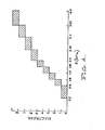
- Figure 4 is a map which relates the frequency F of the first or second formants with the various electrodes in the hearing prosthesis. Where two electrodes are being stimulated to allow perception of Fl and F2 analogues the following rules must apply -
- FIG 3 an advanced form of the invention is shown as a hardwired speech processor.
- the components 20 to 28 are identical to those described with reference to figure 1.
- the amplitude A1 of the first formant is extracted from the output of the filter 49 by means of a rectifier 50 and a low pass filter, 51.
- a summer 54 adds the outputs of attenuators 52 and 53 to provide an appropriate mixture of the amplitudes A1 and A2 to produce the most natural sounding speech sensations.
- the resulting signal is converted to a five bit digital signal by an analogue to digital converter 29.
- the frequency FO of the fundamental voicing component of the speech signal is extracted from the circuit 21 by a rectifier 30, and a 270 Hz low pass filter 31 which together constitute an envelope detector.
- the undulations of the envelope are separated from the DC level by a capacitor 32, and the zero crossings of the envelope are detected by circuit 33, following which the frequency of the zero crossings is converted to a voltage V o by a frequency to voltage converter 34. Subsequently the voltage V is converted by voltage frequency converter 39 to frequency F O ' (the scaled glottal pulse).
- the digital amplitude and frequency data corresponding to the mixed amplitude (A) and second formant frequency (F2) are fed to a 16 k programmable and erasable read only memory (EPROM) 40.
- EPROM programmable and erasable read only memory
- This device accepts the ten bit input and provides two four bit words corresponding to an electrode number and its level of stimulation. It also accepts through the logic selector 47 the eleventh input bit relating to the first or second output word and this information is held in separate parts of the memory of ROM 40 as in the embodiment of figure 1.
- a low pass filter 49 set at approximately 1000 Hz is employed and this is followed by a zero crossing detector 55, a voltage to frequency converter 56, a hysteresis smoothing circuit 57, and an analogue to digital converter 58, in much the same way as the second formant is extracted, differing basically only in the characteristics of the initial filter.
- the means of presentation of the first formant Fl is in the form of a delay between the pulse pairs. This delay is derived from the Fl data via the electrically programmable ROM (EPROM) 59 which is programmed to output delays in the form of a digital quantity appropriate to natural sounding speech as determined by the psychophysical tests.
- EPROM electrically programmable ROM
- the present invention provides a speech processor that is no longer limited to providing a percept to only a two component speech signal but is able to present a percept analogue of a speech signal having three or more formant components.
Landscapes
- Health & Medical Sciences (AREA)
- Otolaryngology (AREA)
- Engineering & Computer Science (AREA)
- Biomedical Technology (AREA)
- Life Sciences & Earth Sciences (AREA)
- Veterinary Medicine (AREA)
- Public Health (AREA)
- General Health & Medical Sciences (AREA)
- Animal Behavior & Ethology (AREA)
- Physics & Mathematics (AREA)
- Psychology (AREA)
- Heart & Thoracic Surgery (AREA)
- Vascular Medicine (AREA)
- Biophysics (AREA)
- Acoustics & Sound (AREA)
- Physiology (AREA)
- Neurology (AREA)
- Nuclear Medicine, Radiotherapy & Molecular Imaging (AREA)
- Radiology & Medical Imaging (AREA)
- Electrotherapy Devices (AREA)
Abstract
Description
- The present invention relates to signal processing systems of the type which are suitable for use with implanted hearing prostheses which electronically stimulate the auditory nerves to produce auditory-like sensations.
- In order to best utilize an auditory prosthesis for speech communication, a signal processor is required which codes the speech signal into a stimulus pattern. Such signal processors in the past have fallen into two general categories:
- 1. Those which stimulate electrodes in regions where, according to the place-pitch theory of hearing, they would be stimulated in a normal hearing person. Stimulation occurs at rates corresponding to the frequency of vibration of that portion of the basilar membrane.
- 2. Those which stimulate at one or more positions in the cochlea but with a stimulus common to all electrodes and at a rate equal or proportional to the glottis pulse rate of the speech signal. Whilst speech processors which fall into
category 1 provide the formant information of the speech signal, they fail to provide prosodic information. Furthermore, since the spectral energy is distributed over broad peaks, confusing percepts may be heard by. the patient. Speech processors which fall intocategory 2 provide the prosodic information important as an aid to lip reading, but fail to provide the necessary formant frequency information. - The invention which is the subject of WO 80/02767 attempted to overcome these disadvantages by providing a speech processor having an output signal in which both formant and prosodic information is present whereby the production of confusing percepts is avoided.
- The speech processor of WO 80/02767 is particularly adapted for use with the implantable hearing prosthesis and the associated stimulation electrode array described in Australian Patent Application Nos. Au-A 41061/78 and AU-A 46563/79 respectively.
- The hearing prosthesis includes an electrode processor having an output signal in which both formant and prosodic information is present whereby the production of confusing percepts is avoided.
- The speech processor according to the invention is particularly adapted for use with the implantable hearing prosthesis and the associated stimulation electrode array described in Australian Patent Application Nos. AU-A 41061/78 and AU-A 46563/79 respectively.
- As described in the earlier Applications referred to above, the hearing prosthesis includes an electrode array which is implanted within the scala tympani region of the cochlea so as to cause.stimulation of the auditory nerve fibres by the application of electrical currents of varying levels of intensity and stimulation frequency. Psychophysical tests are used to determine the sharpness ranking of each electrode and a programmable means within the speech processor is programmed to cause stimulation of selected electrodes depending on the characteristics of at least one of the time varying parameters which essentially described the speech signal within any defined time period.
- Essentially the speech processor WO 80/02767 comprises a signal processing system for converting a speech signal into a data signal for controlling a hearing prosthesis including an implanted electrode array adapted to stimulate the auditory nerve fibres of a patient by the application of electrical currents to selected electrodes in said array, said processing system comprising means for generating an input signal corresponding to a received speech signal, means for estimating the amplitude and frequency of the fundamental voicing component of said speech signal, means for estimating the amplitude and frequency of the second formant component of said speech signal, means for determining whether said speech signal is voiced or unvoiced, programmable means for producing instruction data which in use causes the application of said electrical currents to selected electrodes in said array, said programmable means being programmed with data (Fig. 2) defining a predetermined relationship between each electrode and a selected range of said second formant frequencies based on psychophysical testing of the patient and causing selection of said electrodes based on the estimated frequency of said second formant component such as to produce the desired percepts in the auditory-like sensations generated in the patient, means for causing stimulation of said selected electrode at a frequency dependent on the estimated frequency of said fundamental voicing component for voiced speech signals and at a lower substantially constant frequency for unvoiced speech signals, said programmable means further being programmed to produce data which determines the level of stimulation of each selected electrode dependent on said estimated amplitude of said second formant component of said speech signal as well as on predetermined data relating to the sensitivity of each electrode implanted in the patient.
- The processor of WO 80/02767 was based on the discovery that amplitudes and frequencies of the fundamental voicing component and the second formant component of the speech signal may be successfully used to essentially define the speech signal for utilization by the prosthesis to cause stimulation of the auditory nerves within a patient to produce auditory-like sensations. To achieve thi-s end, the estimated second formant frequency is mapped so that selected segments of the range of second formant frequencies usually experienced are associated with individual electrodes in the array. The mapping is preferably arranged so that the higher levels of the second formant frequency are associated with the electrodes having greater sharpness ranking and the electrodes in the array are then selected according to the map for stimulation as the second formant frequency is estimated. Electrode selection is achieved by programming the programmable means for each particular patient in accordance with the second formant frequency/sharpness map referred to above. The level of stimulation of each electrode and hence the loudness of the corresponding auditory sensation is determined by the estimated amplitude of the second formant component.
- Because of current spread inside the cochlea the number of electrodes providing independent stimulation to different groups of nerve fibres is strictly limited. Thus the number of frequency ranges that can be used to stimulate the electrodes is relatively small. Thus the patients ability to perceive a wide range- of speech signals is limited because of the limitations of the processor to break the speech signals of one speech formant down into a sufficient number of frequency ranges to ensure that heard speech can be rendered into an intelligible form for deaf patients.
- It is an object of this invention to provide a means of increasing the number of frequency ranges which can be converted into separate stimuli for the brain.
- To this end the present invention provides an improvement in the speech processor of WO 80/02767 wherein the programmable means is able to produce instruction data to cause application of electric current to more than one electrode for any one received signal. The received signal may be a single pulse or a pulse train consisting of a number of pulse segments and with the present invention each of these pulses or pulse segments is broken into two portions one of which is delayed.
- Experiments have shown however, that if two electrodes are stimulated by an interleaved pulse train having the same pulse rate, but with one pulse train delayed relative to the other by up to the pulse period, then sensations which are intermediate between those produced by stimulating either electrode alone can be elicited. The sensation produced depends on the delay time and the amplitudes of the two pulse trains.
- This interleaved pulse train technique is used by this invention in addition to single electrode stimuli to provide a means of increasing the number of frequency ranges which can be presented as separate stimuli to the brain. This invention therefore greatly increases the capability of the patient to interpret speech as compared to prior art processes.
- By programming the programmable means, (micro processor) two means for stimulating separate electrodes can be activated so that the output signal for one speech formant from the programmable means is shared between two electrodes.
- An important aspect of this invention is that simultaneous excitation of two electrodes tends to cloud perception because of interaction of the two electrical currents. Thus the programmable means in response to one received signal stimulates one electrode with a predetermined amplitude and then within 0.2 to 5 milliseconds later stimulates a second electrode with a second predetermined amplitude. By varying the amplitude and duration of each electrode stimulation a larger number of recognizable electrode stimuli are available and this means a greater number of discrete frequency ranges within one speech formant can be used by the deaf patient to obtain a greater degree of intelligible data.
- As in the processor of WO 80/02767 the second formant frequency is mapped so that a selected segment of the frequency range corresponds to a particular combination of sequential stimulation of two electrodes with the same or different amplitude at each electrode. By varying the amplitude at one electrode a different frequency segment can be represented. When varying amplitude at one electrode, change in loudness will be experienced unless the amplitude of the other electrode is also altered to retain the same overall amplitude. Variation of this delay can also be used to distinguish between frequency segments.
- It must be noted that the delay between electrode stimulations must be less than the period of output signals from the programmable means. With high frequency segments a shorter delay between electrode stimulation is needed. A preferred delay period for all frequency segments is 0.5 milliseconds.
- Another aspect of the present invention is based on the discovery that percepts produced by electrical stimulation of pairs of. electrodes implanted in the cochlea can have two formant components. The two physical dimensions corresponding to the placement of the two electrodes were related to the two percept dimensions. This can be interpreted as an analogy to the correspondence between two speech formant frequencies in an acoustic presentation and the two dimensions of the resulting percepts.
- It is anticipated that sets of stimuli presented to combinations of three or more electrodes may be used to produce percept analogues to those produced by acoustic signals comprising three or more speech formants.
- Therefore, it is possible to map out the correllation of frequencies of two speech formants and through psychophysical testing using electrical stimulation of two electrodes establish a corresponding two values for electrode stimulation which produces a percept analogue to the acoustic presentation of the two speech formants. This enables a speech processor to be programmed to produce a given set of pulses to a pair of electrodes in respect to a received acoustic speech signal, to produce a percept analogue to said acoustic signal.
- To this end the present invention provides an improvement to the speech processor of WO 80/02767 wherein the means for generating an input signal corresponding to a received speech signal generates a signal having a plurality of formant components and wherein means are provided for estimating the amplitude and frequency of pairs of formant components and wherein the programmable means is able to produce instruction data to cause application of electric current to pairs of electrodes for any one received signal.
- The electric current applied to pairs of electrodes may be applied simultaneously to said electrodes or may be separated by an interval which is small in relation to the average delay between the input signals (either a pulse or pulse train) themselves. This delay may be of the order of 0.2 to 5 milliseconds.
- In this way by stimulating two electrodes with currents to produce in the patient's brain a percept analogue to a speech signal containing a pair of formant components a more complex percept can be simulated. For example, by psychophysical testing to determine percept analogues to speech signals comprising the second and third voicing formants, the computer in the speech processor can be appropriately programmed to produce the percept analogues on receipt of the appropriate input signal. Basically the processor of WO 80/02767 has been modified by adding means to accommodate at least one additional digital word input and means to stimulate two electrodes from one received signal.
- It will be appreciated that in speech, some sounds are unvoiced: they are not produced by a vibration of the glottis, but merely by the movement of the air. Thus, in order to produce the necessary perception of realistic auditory-like sensations within the patient, the speech processor may include means to determine whether the speech signal is voiced or unvoiced at any one time. For this reason, the speech processor may be provided with means for detecting whether the speech signal is voiced or unvoiced and for causing the programmable means to output data to cause stimulation of the selected electrode at a pulse rate which is related to the estimated frequency of the fundamental voicing component of the speech signal for voiced speech components. Where unvoiced speech components are detected, the selected electrodes are stimulated at a lower constant pulse rate which results in a rough sounding percept akin to the unvoiced sound.
- Detection of the voiced or unvoiced nature of the speech signal may be achieved by programming the programmable device to compare the instantaneous values of the second formant frequency and the amplitude of the fundamental voicing component.
- Alternatively, this decision may be made by comparing the low frequency signal energy with the simultaneous high frequency energy.
- It has been discovered that the perception of unvoiced signals may also be learnt by the patient. It has now been discovered that if means for sensing whether a signal is voiced or unvoiced are omitted then a voiced signal will produce recognizable signals while an unvoiced signal will produce random signals which can easily be distinguished by a patient as being an unvoiced signal. This discovery enables one component of the prior art speech processor to be omitted and thus saves space and cost.
- A further aspect of this invention relates to means for providing additional data to the brain relating in response to one speech signal. The number of electrodes implantable in the cochlea is limited. By providing electrical current to two electrodes it is possible to achieve a greater variety of signals that can be discriminated by the brain. Where a pulse is received containing two speech formants, two electrodes can be stimulated with current values to give a percept analogue to those two formants. As mentioned above it is possible to provide an interval between the two electrode currents.
- It has now been discovered that this interval itself can be perceived by the brain and thus can provide information relating to a further speech formant component. For example if the positions of the electrodes selected provide the analogue to the second and third speech formants, then the interval between the current application to the electrodes of any given pair may correspond to an analogue of the first speech formant Fl. Because the frequency ranges of the higher speech formants are usually too high to enable detection by the patient of an interval, this mode of presentation is preferably restricted to the first speech formant Fl.
- In addition the base interval between the pulses themselves can also be patterned to provide an analogue to the glottal pulse rate (fundamental speech formant FO). Thus, the amplitude of the pulses to each electrode, and the interval between pulses on each electrode and the interval between each electrode being stimulated, can carry speech analogue information.
- A preferred embodiment of this invention is as shown in figure 1 of the drawings.
- Referring to the drawings, the simple hardwired speech processor shown in block diagram form is designed to implement with a minimum hardware and power consumption a speech processing strategy based on the presentation of the amplitude and frequency of the second formant only of the speech signal, which is represented by stimulation of two electrodes at a predetermined time interval apart at a rate proportional to the frequency of the fundamental voicing component (glottal pulse frequency FO).
- The system shown includes a
microphone 20 for receiving the speech signal and a preamplifier/automat- icgain control circuit 21 which maintains the output peak signal level nearly constant over a wide range of input signal amplitudes. The second formant frequency F2 is estimated from the output of thecircuit 21 by means of ahigh pass filter 22, a zerocrossings detector 23, a frequency tovoltage converter 24 and ahysteresis circuit 25 which produces a voltage VF2 proportional to F2, following which the voltage is converted to a five bit digital form by an analogue todigital converter 26. Thehigh pass filter 22 is a two pole high pass filter having a 1500 Hz cutoff and a Q=2. The filter has a skirt characteristic which effectively ensures that undesirable contributions to Fe by the first and third formants can be ignored by the zero crossings counter and the RMS- circuit. This ensures that F2 dominates any contributions by the other components. The amplitude A2 of the second formant is extracted from the output of thefilter 22 by means of arectifier 27 and a 35 Hzlow pass filter 28. - The resulting signal is converted to a five bit digital signal by an analogue to
digital converter 29. - The frequency FO of the fundamental voicing component of the speech signal is extracted from the
circuit 21 by arectifier 30, and a 270 Hzlow pass filter 31 which together constitute an envelope detector. The undulations of the envelope are separated from the DC level by acapacitor 32, and the zero crossings of the envelope are detected bycircuit 33, following which the frequency of the zero crossings is converted to a voltage VO by a frequency tovoltage converter 34. - To establish whether the speech signal is voiced or unvoiced, the amplitude of the signal from
rectifier 30 is measured by a 35 Hz lowpass amplitude filter 25 following which it is passed via anattenuator 36 to one input of acomparator 37. As described above, a sound is characteristically unvoiced if its high frequency energy is high compared to its low frequency energy. Thus, by adjusting theattenuator 36, thecomparator 37 can be made to produce a high output for a voiced signal and a low output for an unvoiced signal. - When the output of the
comparator 37 goes high, it actuates aselector switch 38 to pass the voltage VO from the glottal pulse rate extraction path, and when the output of thecomparator 37 goes low, a constant low voltage Vuv is passed to cause stimulation of the implanted electrodes at a low pulse rate, thus producing in the patient a sensation akin to sibilance. - A voltage controlled
oscillator 39 converts the output from theselector switch 38 to a frequency corresponding to the rate of stimulation F 0 - The digital amplitude and frequency data corresponding to the amplitude and frequency of the second formant (A2; F2) are fed to a 16 k programmable and erasable read only memory (EPROM) 40. This device accepts the eleven bit input and provides two four bit words corresponding to an electrode number and its level of stimulation. It also accepts through the
logic selector 47 and 11 bit input relating to the first or second output word and this information is held in separate parts of the memory ofROM 40. The simple selection logic is an integral part for the provision of multiple channel stimulation. As in WO 80/02767 information included in Figs. 2, 3 and 4 of that specification is programmed into theEPROM 40 so that the two four bit words designate the selected electrode and the desired level of stimulation of those electrodes. By using two electrodes to represent the second speech formant frequencies falling between those detectable when only one electrode is stimulated, can be detected. In this way a patient can be taught to perceive a greater number of second speech formant frequencies and thus improve overall voice perception. - The final operation performed by the processor is to code the information into serial data for transmission to the implanted prosthesis. To do this, it is necessary to transmit a synchronization followed by blank seven bit words until the word appropriate to the electrode to be stimulated is reached and then further blank words until 16 words have been transmitted. A second synchronization bit is outputted to initiate stimulation by the implanted prosthesis.
- A four bit
digital comparator 41 is used to compare the desired electrode number with the output of a mod-16counter 42. Thecounter 42 is reset and starts when a scaled "glottal pulse" F 0 is received. The counter -42 counts groups of seven-clock pulses from aclock circuit 46 until the right word is reached. The parallelload shift registers load shift register 45 being 0.5 m.s. behind that ofload shifter 43. This delay in the output fromshift register 45 is preprogrammed with the stimulus level. The outputs ofshift registers circuit 44. The data stream has a synchronization bit added bycircuit 44 and holds the output in the reset mode until the next scaled "glottal pulse" is received. The clock and serial data signals pass on to amplifiers and modulators for transmission to the implanted prosthesis via the power and date coil units described in further detail in the co-pending application referred to above. - Figure 2 represents a modification of the processor illustrated in Figure 1. In this modification, instead of using the stimulation of two electrodes to increase the range of second speech formant frequencies which can be perceived, information corresponding to analogues of the first speech formant Fl are presented with the second formant to pairs of electrodes.
- The modification comprises including after the gain control 21 a
switch 62, a zero crossings counter 63, afrequency voltage converter 64, and ahysteresis circuit 65 which produces a voltage VF1 proportional to the first speech formant Fl. Theswitch 66 enables the voltage VF1 to be converted to a five bit digital form by the analogue todigital converter 26. Whenswitch 62 operates the amplitude A1 of the first formant is extracted by means ofrectifier 27 andlow pass filter 28. - - In this way both Fl and F2 analogues can be produced and presented to pairs of electrodes.
- Figure 4 is a map which relates the frequency F of the first or second formants with the various electrodes in the hearing prosthesis. Where two electrodes are being stimulated to allow perception of Fl and F2 analogues the following rules must apply -
- F2 > Fl when F2 = Fl no differentiation of Fl and F2 can be achieved.
- In figure 3 an advanced form of the invention is shown as a hardwired speech processor. The
components 20 to 28 are identical to those described with reference to figure 1. - In this embodiment additional formant frequencies are analysed to provide a more comprehensive analogue signal. This embodiment also presents an alternative to the Figure 2 embodiment's mode of presenting the first formant analogue.
- The amplitude A1 of the first formant is extracted from the output of the
filter 49 by means of arectifier 50 and a low pass filter, 51. A summer 54, adds the outputs ofattenuators digital converter 29. - The frequency FO of the fundamental voicing component of the speech signal is extracted from the
circuit 21 by arectifier 30, and a 270 Hzlow pass filter 31 which together constitute an envelope detector. The undulations of the envelope are separated from the DC level by acapacitor 32, and the zero crossings of the envelope are detected bycircuit 33, following which the frequency of the zero crossings is converted to a voltage Vo by a frequency tovoltage converter 34. Subsequently the voltage V is converted byvoltage frequency converter 39 to frequency FO' (the scaled glottal pulse). - The digital amplitude and frequency data corresponding to the mixed amplitude (A) and second formant frequency (F2) are fed to a 16 k programmable and erasable read only memory (EPROM) 40. This device accepts the ten bit input and provides two four bit words corresponding to an electrode number and its level of stimulation. It also accepts through the
logic selector 47 the eleventh input bit relating to the first or second output word and this information is held in separate parts of the memory ofROM 40 as in the embodiment of figure 1. - In order to extract the frequency information on the first formant F1, a
low pass filter 49 set at approximately 1000 Hz is employed and this is followed by a zerocrossing detector 55, a voltage tofrequency converter 56, ahysteresis smoothing circuit 57, and an analogue todigital converter 58, in much the same way as the second formant is extracted, differing basically only in the characteristics of the initial filter. - The means of presentation of the first formant Fl is in the form of a delay between the pulse pairs. This delay is derived from the Fl data via the electrically programmable ROM (EPROM) 59 which is programmed to output delays in the form of a digital quantity appropriate to natural sounding speech as determined by the psychophysical tests.
- The remaining functions of the processor are identical to the embodiment described with reference to figure 1.
- From the above it can be seen that the present invention provides a speech processor that is no longer limited to providing a percept to only a two component speech signal but is able to present a percept analogue of a speech signal having three or more formant components.
Claims (9)
Applications Claiming Priority (4)
| Application Number | Priority Date | Filing Date | Title |
|---|---|---|---|
| AUPE692380 | 1980-12-12 | ||
| AU6923/80 | 1980-12-12 | ||
| AUPE950981 | 1981-06-30 | ||
| AU9509/81 | 1981-06-30 |
Publications (3)
| Publication Number | Publication Date |
|---|---|
| EP0054418A2 true EP0054418A2 (en) | 1982-06-23 |
| EP0054418A3 EP0054418A3 (en) | 1982-08-11 |
| EP0054418B1 EP0054418B1 (en) | 1985-08-21 |
Family
ID=25642438
Family Applications (1)
| Application Number | Title | Priority Date | Filing Date |
|---|---|---|---|
| EP81305837A Expired EP0054418B1 (en) | 1980-12-12 | 1981-12-11 | Improvements in speech processors |
Country Status (5)
| Country | Link |
|---|---|
| US (1) | US4515158A (en) |
| EP (1) | EP0054418B1 (en) |
| CA (1) | CA1189147A (en) |
| DE (1) | DE3171951D1 (en) |
| DK (1) | DK549881A (en) |
Cited By (7)
| Publication number | Priority date | Publication date | Assignee | Title |
|---|---|---|---|---|
| EP0124930A1 (en) * | 1983-04-11 | 1984-11-14 | The Commonwealth Of Australia | Cochlear implant system for an auditory prosthesis |
| US4510936A (en) * | 1983-01-20 | 1985-04-16 | National Research Development Corporation | Apparatus for the electrical stimulation of nerves |
| EP0190836A1 (en) * | 1985-01-17 | 1986-08-13 | Ingeborg J. Hochmair | Auditory stimulation using cw and pulsed signals |
| WO1996012383A1 (en) * | 1994-10-17 | 1996-04-25 | The University Of Melbourne | Multiple pulse stimulation |
| WO1998053776A1 (en) * | 1997-05-30 | 1998-12-03 | The University Of Melbourne | Improvements in electrotactile vocoders |
| US5991663A (en) * | 1995-10-17 | 1999-11-23 | The University Of Melbourne | Multiple pulse stimulation |
| CN110662151A (en) * | 2018-06-29 | 2020-01-07 | 国际听力公司 | System and method for identifying hearing aid for infants using voice signals |
Families Citing this family (69)
| Publication number | Priority date | Publication date | Assignee | Title |
|---|---|---|---|---|
| DE3420244A1 (en) * | 1984-05-30 | 1985-12-05 | Hortmann GmbH, 7449 Neckartenzlingen | MULTI-FREQUENCY TRANSMISSION SYSTEM FOR IMPLANTED HEARING PROSTHESES |
| US4617913A (en) * | 1984-10-24 | 1986-10-21 | The University Of Utah | Artificial hearing device and method |
| IL76865A0 (en) * | 1984-11-07 | 1986-02-28 | Audiosonics Neural Communicati | Method and apparatus for communicating information representative of sound waves to the deaf |
| US4648403A (en) * | 1985-05-16 | 1987-03-10 | The Board Of Trustees Of The Leland Stanford Junior University | Method and apparatus for providing spread correction in a multi-channel cochlear prosthesis |
| US4667683A (en) * | 1985-06-11 | 1987-05-26 | Biolectron, Inc. | Audiometer |
| US4823795A (en) * | 1987-03-13 | 1989-04-25 | Minnesota Mining And Manufacturing Company | Signal processor for and an auditory prosthesis having spectral to temporal transformation |
| US4813417A (en) * | 1987-03-13 | 1989-03-21 | Minnesota Mining And Manufacturing Company | Signal processor for and an auditory prosthesis utilizing channel dominance |
| US5271397A (en) * | 1989-09-08 | 1993-12-21 | Cochlear Pty. Ltd. | Multi-peak speech processor |
| US5095904A (en) * | 1989-09-08 | 1992-03-17 | Cochlear Pty. Ltd. | Multi-peak speech procession |
| US5603726A (en) * | 1989-09-22 | 1997-02-18 | Alfred E. Mann Foundation For Scientific Research | Multichannel cochlear implant system including wearable speech processor |
| US5876425A (en) * | 1989-09-22 | 1999-03-02 | Advanced Bionics Corporation | Power control loop for implantable tissue stimulator |
| US5597380A (en) * | 1991-07-02 | 1997-01-28 | Cochlear Ltd. | Spectral maxima sound processor |
| AU681413B2 (en) * | 1993-07-01 | 1997-08-28 | University Of Melbourne, The | Cochlear implant devices |
| WO1995001709A1 (en) | 1993-07-01 | 1995-01-12 | The University Of Melbourne | Cochlear implant devices |
| US5584870A (en) * | 1995-03-09 | 1996-12-17 | Cochlear Ltd. | Implant ESD protection network |
| US5601617A (en) * | 1995-04-26 | 1997-02-11 | Advanced Bionics Corporation | Multichannel cochlear prosthesis with flexible control of stimulus waveforms |
| US5626629A (en) * | 1995-05-31 | 1997-05-06 | Advanced Bionics Corporation | Programming of a speech processor for an implantable cochlear stimulator |
| US6907130B1 (en) | 1998-02-13 | 2005-06-14 | University Of Iowa Research Foundation | Speech processing system and method using pseudospontaneous stimulation |
| US6631295B2 (en) | 1998-02-13 | 2003-10-07 | University Of Iowa Research Foundation | System and method for diagnosing and/or reducing tinnitus |
| US6078838A (en) * | 1998-02-13 | 2000-06-20 | University Of Iowa Research Foundation | Pseudospontaneous neural stimulation system and method |
| JP2002518912A (en) * | 1998-06-08 | 2002-06-25 | コックレア リミティド | Hearing device |
| US6408318B1 (en) | 1999-04-05 | 2002-06-18 | Xiaoling Fang | Multiple stage decimation filter |
| AUPQ161099A0 (en) * | 1999-07-13 | 1999-08-05 | Cochlear Limited | Multirate cochlear stimulation strategy and apparatus |
| US7917224B2 (en) * | 1999-07-21 | 2011-03-29 | Med-El Elektromedizinische Geraete Gmbh | Simultaneous stimulation for low power consumption |
| US8165686B2 (en) * | 1999-08-26 | 2012-04-24 | Med-El Elektromedizinische Geraete Gmbh | Simultaneous intracochlear stimulation |
| JP4819268B2 (en) * | 1999-08-26 | 2011-11-24 | メド−エル・エレクトロメディツィニシェ・ゲラーテ・ゲーエムベーハー | Electrical neural stimulation based on channel-specific sampling sequences |
| US6480820B1 (en) | 1999-09-20 | 2002-11-12 | Advanced Cochlear Systems, Inc. | Method of processing auditory data |
| GB2355607B (en) * | 1999-10-20 | 2002-01-16 | Motorola Israel Ltd | Digital speech processing system |
| AUPQ366799A0 (en) * | 1999-10-26 | 1999-11-18 | University Of Melbourne, The | Emphasis of short-duration transient speech features |
| NL1013500C2 (en) * | 1999-11-05 | 2001-05-08 | Huq Speech Technologies B V | Apparatus for estimating the frequency content or spectrum of a sound signal in a noisy environment. |
| US7822478B2 (en) * | 2000-08-21 | 2010-10-26 | Cochlear Limited | Compressed neural coding |
| US9008786B2 (en) * | 2000-08-21 | 2015-04-14 | Cochlear Limited | Determining stimulation signals for neural stimulation |
| AUPQ952800A0 (en) * | 2000-08-21 | 2000-09-14 | Cochlear Limited | Power efficient electrical stimulation |
| US8285382B2 (en) * | 2000-08-21 | 2012-10-09 | Cochlear Limited | Determining stimulation signals for neural stimulation |
| AUPR604801A0 (en) * | 2001-06-29 | 2001-07-26 | Cochlear Limited | Multi-electrode cochlear implant system with distributed electronics |
| US7155289B1 (en) | 2001-08-17 | 2006-12-26 | Advanced Bionics Corporation | Auto-referencing mixed mode phase locked loop for audio playback applications |
| US7292891B2 (en) * | 2001-08-20 | 2007-11-06 | Advanced Bionics Corporation | BioNet for bilateral cochlear implant systems |
| US7130694B1 (en) * | 2001-12-26 | 2006-10-31 | Advanced Bionics Corporation | Pulse skipping strategy |
| US7894908B2 (en) * | 2003-04-02 | 2011-02-22 | Medtronic, Inc. | Neurostimulation therapy optimization based on a rated session log |
| US7548786B2 (en) | 2003-04-02 | 2009-06-16 | Medtronic, Inc. | Library for management of neurostimulation therapy programs |
| US7489970B2 (en) * | 2003-04-02 | 2009-02-10 | Medtronic, Inc. | Management of neurostimulation therapy using parameter sets |
| US7505815B2 (en) * | 2003-04-02 | 2009-03-17 | Medtronic, Inc. | Neurostimulation therapy usage diagnostics |
| US7463928B2 (en) * | 2003-04-25 | 2008-12-09 | Medtronic, Inc. | Identifying combinations of electrodes for neurostimulation therapy |
| US8036753B2 (en) * | 2004-01-09 | 2011-10-11 | Cochlear Limited | Stimulation mode for cochlear implant speech coding |
| US7941223B2 (en) | 2004-03-08 | 2011-05-10 | Med-El Elektromedizinische Geraete Gmbh | Cochlear implant stimulation with variable number of electrodes |
| US8577473B2 (en) | 2004-03-08 | 2013-11-05 | Med-El Elektromedizinische Geraete Gmbh | Cochlear implant stimulation with low frequency channel privilege |
| AU2005245218B2 (en) | 2004-03-08 | 2010-06-24 | Med-El Elektromedizinische Geraete Gmbh | Electrical stimulation of the acoustic nerve based on selected groups |
| US7794499B2 (en) * | 2004-06-08 | 2010-09-14 | Theken Disc, L.L.C. | Prosthetic intervertebral spinal disc with integral microprocessor |
| CA2573785A1 (en) * | 2004-07-20 | 2006-02-02 | Medtronic, Inc. | Therapy programming guidance based on stored programming history |
| US7819909B2 (en) * | 2004-07-20 | 2010-10-26 | Medtronic, Inc. | Therapy programming guidance based on stored programming history |
| US20060025833A1 (en) * | 2004-07-29 | 2006-02-02 | Cochlear Limited | Variable width electrode scheme |
| US7421298B2 (en) * | 2004-09-07 | 2008-09-02 | Cochlear Limited | Multiple channel-electrode mapping |
| US8369958B2 (en) * | 2005-05-19 | 2013-02-05 | Cochlear Limited | Independent and concurrent processing multiple audio input signals in a prosthetic hearing implant |
| US7774067B2 (en) * | 2006-04-12 | 2010-08-10 | Medtronic, Inc. | Autogeneration of neurostimulation therapy program groups |
| US8712539B2 (en) | 2006-04-12 | 2014-04-29 | Medtronic, Inc. | Rule-based stimulation program search |
| US8019430B2 (en) * | 2007-03-21 | 2011-09-13 | Cochlear Limited | Stimulating auditory nerve fibers to provide pitch representation |
| CA2704623C (en) * | 2007-11-09 | 2015-03-17 | Med-El Elektromedizinische Geraete Gmbh | Pulsatile cochlear implant stimulation strategy |
| AU2009239648B2 (en) | 2008-04-22 | 2013-08-15 | Med-El Elektromedizinische Geraete Gmbh | Tonotopic implant stimulation |
| AU2009333567B2 (en) * | 2008-12-08 | 2012-11-01 | Med-El Elektromedizinische Geraete Gmbh | Method for fitting a cochlear implant with patient feedback |
| WO2010085477A1 (en) | 2009-01-20 | 2010-07-29 | Med-El Elektromedizinische Geraete Gmbh | High accuracy tonotopic and periodic coding with enhanced harmonic resolution |
| WO2010088324A1 (en) * | 2009-01-28 | 2010-08-05 | Med-El Elktromedizinische Geraete Gmbh | Channel specific gain control including lateral suppression |
| WO2010091240A1 (en) * | 2009-02-06 | 2010-08-12 | Med-El Elektromedizinische Geraete Gmbh | Phase triggered envelope sampler |
| EP2411089B1 (en) * | 2009-03-24 | 2017-06-21 | MED-EL Elektromedizinische Geräte GmbH | Musical fitting of cochlear implants |
| US8019429B2 (en) * | 2009-03-24 | 2011-09-13 | Med-El Elektromedizinische Geraete Gmbh | Carrier and envelope triggered cochlear stimulation |
| US20100300007A1 (en) * | 2009-05-27 | 2010-12-02 | Bunts Sr John F | Storm shelter and components thereof |
| WO2012037305A1 (en) | 2010-09-15 | 2012-03-22 | Med-El Elektromedizinische Geraete Gmbh | Method and system for accelerated fitting of cochlear implants based on current spread |
| US11813454B2 (en) | 2010-11-11 | 2023-11-14 | IINN, Inc. | Methods of bypassing neurological damage through motor nerve root stimulation |
| US8515540B2 (en) | 2011-02-24 | 2013-08-20 | Cochlear Limited | Feedthrough having a non-linear conductor |
| US9384759B2 (en) * | 2012-03-05 | 2016-07-05 | Malaspina Labs (Barbados) Inc. | Voice activity detection and pitch estimation |
Family Cites Families (8)
| Publication number | Priority date | Publication date | Assignee | Title |
|---|---|---|---|---|
| US3752939A (en) * | 1972-02-04 | 1973-08-14 | Beckman Instruments Inc | Prosthetic device for the deaf |
| US4051331A (en) * | 1976-03-29 | 1977-09-27 | Brigham Young University | Speech coding hearing aid system utilizing formant frequency transformation |
| US4063048A (en) * | 1977-03-16 | 1977-12-13 | Kissiah Jr Adam M | Implantable electronic hearing aid |
| FR2383657A1 (en) * | 1977-03-16 | 1978-10-13 | Bertin & Cie | EQUIPMENT FOR HEARING AID |
| CA1100189A (en) * | 1977-11-03 | 1981-04-28 | Ian C. Forster | Inner ear stimulating prosthesis |
| GB2016276B (en) * | 1978-01-21 | 1982-02-10 | Ross Foundation For Research I | Sensory system |
| WO1980002767A1 (en) * | 1979-05-28 | 1980-12-11 | Univ Melbourne | Speech processor |
| US4284856A (en) * | 1979-09-24 | 1981-08-18 | Hochmair Ingeborg | Multi-frequency system and method for enhancing auditory stimulation and the like |
-
1981
- 1981-12-08 CA CA000391699A patent/CA1189147A/en not_active Expired
- 1981-12-11 DE DE8181305837T patent/DE3171951D1/en not_active Expired
- 1981-12-11 DK DK549881A patent/DK549881A/en not_active Application Discontinuation
- 1981-12-11 EP EP81305837A patent/EP0054418B1/en not_active Expired
- 1981-12-11 US US06/329,986 patent/US4515158A/en not_active Expired - Fee Related
Cited By (13)
| Publication number | Priority date | Publication date | Assignee | Title |
|---|---|---|---|---|
| US4510936A (en) * | 1983-01-20 | 1985-04-16 | National Research Development Corporation | Apparatus for the electrical stimulation of nerves |
| AU597661B2 (en) * | 1983-04-11 | 1990-06-07 | Commonwealth Of Australia, The | Cochlear implant system with psychophysical testing or programming with mapped patient responses provided to encoder |
| US4532930A (en) * | 1983-04-11 | 1985-08-06 | Commonwealth Of Australia, Dept. Of Science & Technology | Cochlear implant system for an auditory prosthesis |
| EP0124930A1 (en) * | 1983-04-11 | 1984-11-14 | The Commonwealth Of Australia | Cochlear implant system for an auditory prosthesis |
| EP0241101A1 (en) * | 1983-04-11 | 1987-10-14 | The Commonwealth Of Australia | Cochlear implant system with psychological testing or programming with mapped patient responses provided to encoder |
| EP0247649A1 (en) * | 1983-04-11 | 1987-12-02 | The Commonwealth Of Australia | Cochlear implant prosthesis current switching and power supply |
| AU595883B2 (en) * | 1983-04-11 | 1990-04-12 | Commonwealth Of Australia, The | Implant prosthesis current switching and power supply |
| EP0190836A1 (en) * | 1985-01-17 | 1986-08-13 | Ingeborg J. Hochmair | Auditory stimulation using cw and pulsed signals |
| WO1996012383A1 (en) * | 1994-10-17 | 1996-04-25 | The University Of Melbourne | Multiple pulse stimulation |
| US5991663A (en) * | 1995-10-17 | 1999-11-23 | The University Of Melbourne | Multiple pulse stimulation |
| WO1998053776A1 (en) * | 1997-05-30 | 1998-12-03 | The University Of Melbourne | Improvements in electrotactile vocoders |
| US6466911B1 (en) | 1997-05-30 | 2002-10-15 | The University Of Melbourne | Electrotactile vocoder using handset with stimulating electrodes |
| CN110662151A (en) * | 2018-06-29 | 2020-01-07 | 国际听力公司 | System and method for identifying hearing aid for infants using voice signals |
Also Published As
| Publication number | Publication date |
|---|---|
| US4515158A (en) | 1985-05-07 |
| DE3171951D1 (en) | 1985-09-26 |
| EP0054418B1 (en) | 1985-08-21 |
| EP0054418A3 (en) | 1982-08-11 |
| DK549881A (en) | 1982-06-13 |
| CA1189147A (en) | 1985-06-18 |
Similar Documents
| Publication | Publication Date | Title |
|---|---|---|
| EP0054418B1 (en) | Improvements in speech processors | |
| US4441202A (en) | Speech processor | |
| US9393414B2 (en) | Inner hair cell stimulation model for use by a cochlear implant system | |
| Blamey et al. | Vowel and consonant recognition of cochlear implant patients using formant‐estimating speech processors | |
| Wilson et al. | Comparative studies of speech processing strategies for cochlear implants | |
| US7333858B2 (en) | Pulse burst electrical stimulation of nerve or tissue fibers | |
| US5991663A (en) | Multiple pulse stimulation | |
| Kiang et al. | Fundamental considerations in designing auditory implants | |
| Geurts et al. | Better place-coding of the fundamental frequency in cochlear implants | |
| CA2202868A1 (en) | Multiple pulse stimulation | |
| Geurts et al. | Enhancing the speech envelope of continuous interleaved sampling processors for cochlear implants | |
| Eisen | The history of cochlear implants | |
| US6064913A (en) | Multiple pulse stimulation | |
| AU2005202837B2 (en) | Selective resolution speech processing | |
| Blamey et al. | A comparison of three speech coding strategies using an acoustic model of a cochlear implant | |
| Pickett et al. | Auditory implants and tactile aids for the profoundly deaf | |
| JPS645900B2 (en) | ||
| Wilson et al. | Representations of speech features with cochlear implants | |
| Hood et al. | Discrimination of complex speech-related signals with a multichannel electronic cochlear implant as measured by adaptive procedures | |
| Thomas et al. | Music perception and cochlear implants—A review of major breakthroughs | |
| Hanekom et al. | The South Africa bionic ear-description and preliminary results | |
| White et al. | Formant discrimination in a multichannel cochlear prosthesis | |
| White | Cochlear prostheses: Stochastic model of electrical excitation | |
| Widin et al. | Perceptual similarity of complex signals presented by electrical stimulation of the auditory nerve | |
| Laback et al. | Perceptual grouping of tone sequences in cochlear implant stimulation |
Legal Events
| Date | Code | Title | Description |
|---|---|---|---|
| PUAI | Public reference made under article 153(3) epc to a published international application that has entered the european phase |
Free format text: ORIGINAL CODE: 0009012 |
|
| PUAL | Search report despatched |
Free format text: ORIGINAL CODE: 0009013 |
|
| AK | Designated contracting states |
Designated state(s): AT CH DE FR GB IT LI NL SE |
|
| AK | Designated contracting states |
Designated state(s): AT CH DE FR GB IT LI NL SE |
|
| 17P | Request for examination filed |
Effective date: 19821029 |
|
| ITF | It: translation for a ep patent filed | ||
| GRAA | (expected) grant |
Free format text: ORIGINAL CODE: 0009210 |
|
| RBV | Designated contracting states (corrected) |
Designated state(s): DE FR GB IT |
|
| AK | Designated contracting states |
Designated state(s): DE FR GB IT |
|
| REF | Corresponds to: |
Ref document number: 3171951 Country of ref document: DE Date of ref document: 19850926 |
|
| ET | Fr: translation filed | ||
| PLBE | No opposition filed within time limit |
Free format text: ORIGINAL CODE: 0009261 |
|
| STAA | Information on the status of an ep patent application or granted ep patent |
Free format text: STATUS: NO OPPOSITION FILED WITHIN TIME LIMIT |
|
| 26N | No opposition filed | ||
| ITTA | It: last paid annual fee | ||
| PGFP | Annual fee paid to national office [announced via postgrant information from national office to epo] |
Ref country code: GB Payment date: 19951208 Year of fee payment: 15 |
|
| PGFP | Annual fee paid to national office [announced via postgrant information from national office to epo] |
Ref country code: DE Payment date: 19951222 Year of fee payment: 15 |
|
| PGFP | Annual fee paid to national office [announced via postgrant information from national office to epo] |
Ref country code: FR Payment date: 19951229 Year of fee payment: 15 |
|
| PG25 | Lapsed in a contracting state [announced via postgrant information from national office to epo] |
Ref country code: GB Effective date: 19961211 |
|
| GBPC | Gb: european patent ceased through non-payment of renewal fee |
Effective date: 19961211 |
|
| PG25 | Lapsed in a contracting state [announced via postgrant information from national office to epo] |
Ref country code: FR Effective date: 19970829 |
|
| PG25 | Lapsed in a contracting state [announced via postgrant information from national office to epo] |
Ref country code: DE Effective date: 19970902 |
|
| REG | Reference to a national code |
Ref country code: FR Ref legal event code: ST |