EP0053830A1 - Cell - Google Patents
Cell Download PDFInfo
- Publication number
- EP0053830A1 EP0053830A1 EP81110230A EP81110230A EP0053830A1 EP 0053830 A1 EP0053830 A1 EP 0053830A1 EP 81110230 A EP81110230 A EP 81110230A EP 81110230 A EP81110230 A EP 81110230A EP 0053830 A1 EP0053830 A1 EP 0053830A1
- Authority
- EP
- European Patent Office
- Prior art keywords
- gasket
- glass beads
- synthetic resin
- cell
- positive
- Prior art date
- Legal status (The legal status is an assumption and is not a legal conclusion. Google has not performed a legal analysis and makes no representation as to the accuracy of the status listed.)
- Granted
Links
Images
Classifications
-
- H—ELECTRICITY
- H01—ELECTRIC ELEMENTS
- H01M—PROCESSES OR MEANS, e.g. BATTERIES, FOR THE DIRECT CONVERSION OF CHEMICAL ENERGY INTO ELECTRICAL ENERGY
- H01M50/00—Constructional details or processes of manufacture of the non-active parts of electrochemical cells other than fuel cells, e.g. hybrid cells
- H01M50/10—Primary casings; Jackets or wrappings
- H01M50/183—Sealing members
- H01M50/186—Sealing members characterised by the disposition of the sealing members
-
- H—ELECTRICITY
- H01—ELECTRIC ELEMENTS
- H01M—PROCESSES OR MEANS, e.g. BATTERIES, FOR THE DIRECT CONVERSION OF CHEMICAL ENERGY INTO ELECTRICAL ENERGY
- H01M50/00—Constructional details or processes of manufacture of the non-active parts of electrochemical cells other than fuel cells, e.g. hybrid cells
- H01M50/10—Primary casings; Jackets or wrappings
- H01M50/183—Sealing members
- H01M50/184—Sealing members characterised by their shape or structure
-
- H—ELECTRICITY
- H01—ELECTRIC ELEMENTS
- H01M—PROCESSES OR MEANS, e.g. BATTERIES, FOR THE DIRECT CONVERSION OF CHEMICAL ENERGY INTO ELECTRICAL ENERGY
- H01M50/00—Constructional details or processes of manufacture of the non-active parts of electrochemical cells other than fuel cells, e.g. hybrid cells
- H01M50/10—Primary casings; Jackets or wrappings
- H01M50/183—Sealing members
- H01M50/19—Sealing members characterised by the material
- H01M50/193—Organic material
-
- Y—GENERAL TAGGING OF NEW TECHNOLOGICAL DEVELOPMENTS; GENERAL TAGGING OF CROSS-SECTIONAL TECHNOLOGIES SPANNING OVER SEVERAL SECTIONS OF THE IPC; TECHNICAL SUBJECTS COVERED BY FORMER USPC CROSS-REFERENCE ART COLLECTIONS [XRACs] AND DIGESTS
- Y02—TECHNOLOGIES OR APPLICATIONS FOR MITIGATION OR ADAPTATION AGAINST CLIMATE CHANGE
- Y02E—REDUCTION OF GREENHOUSE GAS [GHG] EMISSIONS, RELATED TO ENERGY GENERATION, TRANSMISSION OR DISTRIBUTION
- Y02E60/00—Enabling technologies; Technologies with a potential or indirect contribution to GHG emissions mitigation
- Y02E60/10—Energy storage using batteries
-
- Y—GENERAL TAGGING OF NEW TECHNOLOGICAL DEVELOPMENTS; GENERAL TAGGING OF CROSS-SECTIONAL TECHNOLOGIES SPANNING OVER SEVERAL SECTIONS OF THE IPC; TECHNICAL SUBJECTS COVERED BY FORMER USPC CROSS-REFERENCE ART COLLECTIONS [XRACs] AND DIGESTS
- Y10—TECHNICAL SUBJECTS COVERED BY FORMER USPC
- Y10S—TECHNICAL SUBJECTS COVERED BY FORMER USPC CROSS-REFERENCE ART COLLECTIONS [XRACs] AND DIGESTS
- Y10S277/00—Seal for a joint or juncture
- Y10S277/935—Seal made of a particular material
- Y10S277/936—Composite
- Y10S277/937—Glass particles or filament
Definitions
- the present invention relates to a cell improved in leak-proof property. More particularly it relates to a cell provided with a synthetic resin gasket comprising glass . beads, which has an excellent leak-proof property.
- sealing is usually effected by setting a gasket made of a synthetic resin into the opening of a positive can and crimping the flange of the positive can inwardly to press the gasket against a negative collector so that the contacting surfaces of the positive can, the gasket and the.negative collector are closely contacted one another to prevent leaking of an electrolyte from the contacting surfaces.
- synthetic resin gasket does not have a sufficient elasticity for prevention of leakage of the electrolyte, and also the deterioration of its elasticity is caused by adsorption of the electrolyte so that the leak-proof property is lowered.
- a synthetic resin gasket comprising glass fibers, which is prepared by incorporating the glass fibers into a synthetic resin and molding the resultant composition into a gasket shape. While this gasket is improved in tensile strength and compressive strength, the glass fibers are partially projected onto the surface of the gasket to deteriorate the smoothness of such surface. Further, an electrolyte comes into the inside of the gasket along the projected glass fibers, whereby the leak-proof property is lowered. Moreover, glass fibers are dispersed unevenly into a synthetic resin and increase its viscosity so that the resulting composition is made inferior in fluidity, while such composition is hardly shrinked evenly. Thus, the production of gaskets with good size precision is quite difficult.
- a cell comprising a positive can and a negative collector fitted in the opening of the positive can, a gasket being. set in the space between the positive can and the negative collector to prevent the leakage of any liquid material in the cell, characterized in that the gasket is made of a synthetic resin composition comprising glass beads.
- the synthetic resin composition of which the gasket is made comprises at least one synthetic resin and glass beads.
- the synthetic resin there may be used a polyamide (e.g. nylon 6, nylon 66, nylon 610, nylon 11, nylon 12), a polyolefin (e.g. polyethylene, polypropylene, ethylene-propylene copolymer) or the like.
- the kind of the synthetic resin may be selected appropriately depending upon the properties of an electrolyte. For example, in an alkaline cell with an alkaline electrolyte, the use of a polyamide, especially nylon 11 or nylon 12, is preferred. In an organic electrolyte cell using a non-aqueous solution, it is preferred to employ a polyolefin, especially polypropylene.
- the glass beads are micro-spherical particles of glass, which may be prepared, for instance, by blowing glass particles into a flame of high temperature, whereby the particles are melted in a floating state to become spherical due to their own surface tension. They are of true spherical shape, smooth surface and extremely small particle size.
- the glass beads have usually an average particle size of 2 to 60 ⁇ m.
- the particle size is smaller, the production of the glass beads is difficult, and further the glass beads are apt to cohere one another on treatment with a coupling agent.
- the particle size is larger, the glass beads become linked together in the gasket to cause leakage of an electrolyte. Further, by the pressure applied on sealing, the glass beads are apt to be broken to lose their packing function. Furthermore, the fluidity of the synthetic resin composition is lowered on molding of the .gasket.
- the composition of glass for the glass beads is not specifically limited, the one of non-alkali glass (E-glass) is preferable.
- the glass beads are preferably surface-treated with a coupling agent such as a silane coupling agent (e.g. aminosilane, glycidosilane, acrylsilane) or a titanate coupling agent (e.g. isopropyl triisostearoyl titanate, isopropyl tridodecylbenzenesulfonyl titanate, isopropyl tris(dioctyl pyrophosphate) titanate).
- a coupling agent such as a silane coupling agent (e.g. aminosilane, glycidosilane, acrylsilane) or a titanate coupling agent (e.g. isopropyl triisostearoyl titanate, isopropyl tridodecylbenzenesulfonyl titanate, isopropyl
- the glass beads When incorporated into a synthetic resin, the glass beads show a good dispersibility due to the bearing effect based on their spherical shape. Further, they serve to improve the fluidity of the synthetic resin composition, and the smooth flow of such composition into a mold can be' attained. As their surfaces are smooth, the increase of the viscosity in the synthetic resin composition is relatively small, and a comparatively large amount of such composition can be filled in a mold.
- the amount of the glass beads in the synthetic resin composition may be usually from 5 to 50 % by weight, preferably from 20 to 40 % by weight. When the amount.is smaller, the desired technical effect is not achieved. When the amount is larger, the leakage routes of an electrolyte are formed in the resulting gasket due to the mutual contacts of the glass beads.
- Incorporation of the glass beads into the synthetic resin is preferably carried out when the synthetic resin is in a melt state.
- the resulting mixtue may be cooled and then pelletized for storage.
- Preparation of the gasket by the use of such pellets is normally accomplished by injection molding.
- the gasket made of the synthetic resin composition is improved in tensile strength, flexural strength, etc., especially in compressive strength, and have an increased elasticity so that efficient sealing with a high clamping pressure is possilbe.
- the contacting surfaces of the positive can, the gasket and the negative collector are tightly closed, and such state can be maintained for a long period of time.
- the leak-proof property of the resulting cell is thus remarkably improved.
- such gasket shows a lower liquid absorbing property than that comprising no glass beads.
- glass beads are less linked together in the gasket and further less projected to the gasket surface, such gasket has a smooth surface and is free from invasion of an electrolyte into its inside.
- the elasticity of the gasket is hardly lowered.
- glass beads are isotropic in shape, the gasket produces less deformation on shrinkage and has an evenly dispersed stress. Therefore, the gasket can be easily molded with high size precision and is scarcely broken by stress.
- annular gaskets of L-letter shape in cross-section with an outer diameter of 11.1 mm, a diameter of the portion to be in contact with a positive can of 10.1 mm and a height of 1.18 mm were prepared by injection molding. Each of these gaskets was. fitted into the peripheral part of a negative collector. Using such combination of the gasket and the negative collector, an alkaline cell of button type as shown in Fig. 2 of the accompanying drawings was assembled in the following manner:
- a portion of an electrolyte was poured into the bottom part of an positive can (1).
- a positive mix (2) was inserted into the positive can (1).
- a separator (3) comprising a microporous polypropylene film (4), a cellophane film (5) and a vinylon-rayon mixed paper sheet (6).
- the negative collector (8) containing a negative electrode mix (7) comprising amalgamated zinc as a negative active material and sodium polyacrylate and the remaining portion of the electrolyte was engaged.
- the flange of the positive can (1) was crimped inwardly to press the gasket (9) against the negative collector (8) to seal the opening, thereby assembling a button type alkaline cell.
- the electrolyte for the above cell there was used an aqueous solution of potassium hydroxide (35 %) containing zinc oxide in a concentration of 5.2 t.
- the negative collector (8) was prepared by the use of a clad plate.comprising a steel layer, a nickel layer on the outside surface and a copper layer on the inside surface and formed into a shape having a peripheral lappet portion (10) by drawing.
- the positive can (1) was made of a nickel plated iron plate.
- the positive mix (2) was a mixture of silver(I) oxide (150 parts) and graphite (10 parts) molded in one piece with a stainless steel annular base plate (11) under a pressure of 5 t/cm 2 .
- Each cell had a button shape with a diameter of 11 mm and a thickness of 3.0 mm.
- a sealant material comprising asphalt pitch (a mixture of asphalt with process oil).
- the cell of the invention showed a favorable leak-proof property, particularly when the amount of the glass beads was in a range of 20 to 40 %. With a larger particle size of the glass beads, the leak-proof property of the cell lowered. In the case where the surface treatment was not effected, the improvement in liquid-proof property was smaller in comparison with the case where the surface treatment with a coupling agent was effected. With regard to nylon 11, the increase of the amount of the glass beads to about 60 % made the gasket fragile and caused cracks in the gasket on the sealing so that the gasket became unsuitable for assembly into a cell. Besides, it was understood that when the glass fibers were used in place of the glass beads, the leak-proof property of the cell was remarkably lowered.
- a lithium disc having a diameter of 14 mm and a thickness of 0.25 mm was pressed into a stainless steel net (22) spot-welded to the inner surface of the negative collector (21) to make a negative electrode mix (23). Then, a separator (24) comprising a non-woven fabric of polypropylene was placed therein, and a majority portion of the electrolyte was poured therein.
- the electrolyte for above the cell there was used a solution of lithium perchlorate in a mixed solvent of propylene carbonate and 1,2-dimethoxyethane in a weight proportion of ' 35 : 65 at a concentration of 0.5 mol/liter.
- the negative collector (21) and the positive can (27) there were used those made of a nickel-stainless steel clad plate.
- Each cell had a button shape with a diameter of 20 mm and a thickness of 1.6 mm.
- the cell of the invention showed a fovorable leak-proof property especially when the amount of the glass beads was in a range of 20 to 40 %. With a larger particle size of the glass beads, the leak-proof property of the cell lowered. In the case where the surface treatment was not effected, the improvement in leak-proof property was smaller in comparison with the case where the surface treatment with a coupling agent was effected.
Landscapes
- Chemical & Material Sciences (AREA)
- Chemical Kinetics & Catalysis (AREA)
- Electrochemistry (AREA)
- General Chemical & Material Sciences (AREA)
- Sealing Battery Cases Or Jackets (AREA)
Abstract
Description
- The present invention relates to a cell improved in leak-proof property. More particularly it relates to a cell provided with a synthetic resin gasket comprising glass . beads, which has an excellent leak-proof property.
- In conventional cells, sealing is usually effected by setting a gasket made of a synthetic resin into the opening of a positive can and crimping the flange of the positive can inwardly to press the gasket against a negative collector so that the contacting surfaces of the positive can, the gasket and the.negative collector are closely contacted one another to prevent leaking of an electrolyte from the contacting surfaces. However, such synthetic resin gasket does not have a sufficient elasticity for prevention of leakage of the electrolyte, and also the deterioration of its elasticity is caused by adsorption of the electrolyte so that the leak-proof property is lowered.
- Many attempts have heretofore been made to overcome the said drawback. For example, the modification of the shape of the negative collector for improving the leak-proof property has been proposed. Further, for example, the application of a sealant material to the. contacting surfaces of the gasket with the positive can and the negative collector has been proposed. However, even these proposals can not provide a satisfying leak-proof property.
- Among the proposals as recently made, there is the use of a synthetic resin gasket comprising glass fibers, which is prepared by incorporating the glass fibers into a synthetic resin and molding the resultant composition into a gasket shape. While this gasket is improved in tensile strength and compressive strength, the glass fibers are partially projected onto the surface of the gasket to deteriorate the smoothness of such surface. Further, an electrolyte comes into the inside of the gasket along the projected glass fibers, whereby the leak-proof property is lowered. Moreover, glass fibers are dispersed unevenly into a synthetic resin and increase its viscosity so that the resulting composition is made inferior in fluidity, while such composition is hardly shrinked evenly. Thus, the production of gaskets with good size precision is quite difficult.
- It has now been found that a cell provided with a gasket made of a synthetic resin composition comprising glass beads can maintain an excellent leak-proof property for a long period of time.
- According to this invention, there is provided a cell comprising a positive can and a negative collector fitted in the opening of the positive can, a gasket being. set in the space between the positive can and the negative collector to prevent the leakage of any liquid material in the cell, characterized in that the gasket is made of a synthetic resin composition comprising glass beads.
- The synthetic resin composition of which the gasket is made comprises at least one synthetic resin and glass beads. As the synthetic resin, there may be used a polyamide (e.g. nylon 6, nylon 66, nylon 610,
nylon 11, nylon 12), a polyolefin (e.g. polyethylene, polypropylene, ethylene-propylene copolymer) or the like. The kind of the synthetic resin may be selected appropriately depending upon the properties of an electrolyte. For example, in an alkaline cell with an alkaline electrolyte, the use of a polyamide, especiallynylon 11 or nylon 12, is preferred. In an organic electrolyte cell using a non-aqueous solution, it is preferred to employ a polyolefin, especially polypropylene. - The glass beads are micro-spherical particles of glass, which may be prepared, for instance, by blowing glass particles into a flame of high temperature, whereby the particles are melted in a floating state to become spherical due to their own surface tension. They are of true spherical shape, smooth surface and extremely small particle size.
- The glass beads have usually an average particle size of 2 to 60 µm. When the particle size is smaller, the production of the glass beads is difficult, and further the glass beads are apt to cohere one another on treatment with a coupling agent. When the particle size is larger, the glass beads become linked together in the gasket to cause leakage of an electrolyte. Further, by the pressure applied on sealing, the glass beads are apt to be broken to lose their packing function. Furthermore, the fluidity of the synthetic resin composition is lowered on molding of the .gasket.
- Though the composition of glass for the glass beads is not specifically limited, the one of non-alkali glass (E-glass) is preferable. Also, the glass beads are preferably surface-treated with a coupling agent such as a silane coupling agent (e.g. aminosilane, glycidosilane, acrylsilane) or a titanate coupling agent (e.g. isopropyl triisostearoyl titanate, isopropyl tridodecylbenzenesulfonyl titanate, isopropyl tris(dioctyl pyrophosphate) titanate). Specific examples of the glass beads as commercially available include Toshiba Glass Beads (manufactured by Toshiba Ballotini Co., Ltd.).
- When incorporated into a synthetic resin, the glass beads show a good dispersibility due to the bearing effect based on their spherical shape. Further, they serve to improve the fluidity of the synthetic resin composition, and the smooth flow of such composition into a mold can be' attained. As their surfaces are smooth, the increase of the viscosity in the synthetic resin composition is relatively small, and a comparatively large amount of such composition can be filled in a mold.
- The amount of the glass beads in the synthetic resin composition may be usually from 5 to 50 % by weight, preferably from 20 to 40 % by weight. When the amount.is smaller, the desired technical effect is not achieved. When the amount is larger, the leakage routes of an electrolyte are formed in the resulting gasket due to the mutual contacts of the glass beads.
- Incorporation of the glass beads into the synthetic resin is preferably carried out when the synthetic resin is in a melt state. The resulting mixtue may be cooled and then pelletized for storage. Preparation of the gasket by the use of such pellets is normally accomplished by injection molding.
- The gasket made of the synthetic resin composition is improved in tensile strength, flexural strength, etc., especially in compressive strength, and have an increased elasticity so that efficient sealing with a high clamping pressure is possilbe. As the result, the contacting surfaces of the positive can, the gasket and the negative collector are tightly closed, and such state can be maintained for a long period of time. The leak-proof property of the resulting cell is thus remarkably improved. Further, such gasket shows a lower liquid absorbing property than that comprising no glass beads. As glass beads are less linked together in the gasket and further less projected to the gasket surface, such gasket has a smooth surface and is free from invasion of an electrolyte into its inside. Thus, the elasticity of the gasket is hardly lowered. Furthermore, since glass beads are isotropic in shape, the gasket produces less deformation on shrinkage and has an evenly dispersed stress. Therefore, the gasket can be easily molded with high size precision and is scarcely broken by stress.
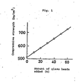
- In the case where a gasket is prepared by the use of a synthetic resin
composition comprising nylon 11 and glass beads of 30 µm in average particle size, the relationship between the compressive strength of the gasket and the amount of the glass beads employed is-shown in Fig. 1 of the accompanying drawings, from which it may be understood that the compressive strength of the gasket is enhanced with the increase of the amount of the glass beads. - Practical and presently preferred embodiments of the present invention are illustratively shown in the following Examples and Comparative Examples, wherein part(s) and % are by weight unless otherwise indicated.
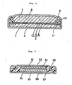
- By the use of a synthetic resin composition comprising glass beads as shown in Table 1, annular gaskets of L-letter shape in cross-section with an outer diameter of 11.1 mm, a diameter of the portion to be in contact with a positive can of 10.1 mm and a height of 1.18 mm were prepared by injection molding. Each of these gaskets was. fitted into the peripheral part of a negative collector. Using such combination of the gasket and the negative collector, an alkaline cell of button type as shown in Fig. 2 of the accompanying drawings was assembled in the following manner:
- A portion of an electrolyte was poured into the bottom part of an positive can (1). Into the positive can (1), a positive mix (2) was inserted. On the positive mix (2), there was placed a separator (3) comprising a microporous polypropylene film (4), a cellophane film (5) and a vinylon-rayon mixed paper sheet (6). With the positive can (1), the negative collector (8) containing a negative electrode mix (7) comprising amalgamated zinc as a negative active material and sodium polyacrylate and the remaining portion of the electrolyte was engaged. Then, the flange of the positive can (1) was crimped inwardly to press the gasket (9) against the negative collector (8) to seal the opening, thereby assembling a button type alkaline cell.
- As the electrolyte for the above cell, there was used an aqueous solution of potassium hydroxide (35 %) containing zinc oxide in a concentration of 5.2 t. The negative collector (8) was prepared by the use of a clad plate.comprising a steel layer, a nickel layer on the outside surface and a copper layer on the inside surface and formed into a shape having a peripheral lappet portion (10) by drawing. The positive can (1) was made of a nickel plated iron plate. The positive mix (2) was a mixture of silver(I) oxide (150 parts) and graphite (10 parts) molded in one piece with a stainless steel annular base plate (11) under a pressure of 5 t/cm2. Each cell had a button shape with a diameter of 11 mm and a thickness of 3.0 mm. On the contact surfaces of the gasket (9) with the positive can (1) and the negative collector (8) in the cell, there were interposed a sealant material comprising asphalt pitch (a mixture of asphalt with process oil).
- Every 100 pieces of cells thus assembled were stored at a temperature of 80°C under a relative humidity of 90 %, and the number of the cells which produced leakage of the electrolyte was counted. The results are shown in Table 2.


- As shown in Table 2, the cell of the invention showed a favorable leak-proof property, particularly when the amount of the glass beads was in a range of 20 to 40 %. With a larger particle size of the glass beads, the leak-proof property of the cell lowered. In the case where the surface treatment was not effected, the improvement in liquid-proof property was smaller in comparison with the case where the surface treatment with a coupling agent was effected. With regard to
nylon 11, the increase of the amount of the glass beads to about 60 % made the gasket fragile and caused cracks in the gasket on the sealing so that the gasket became unsuitable for assembly into a cell. Besides, it was understood that when the glass fibers were used in place of the glass beads, the leak-proof property of the cell was remarkably lowered. - Using a synthetic resin composition comprising glass beads as shown in Table 3, an annular gasket was insert-molded by injection molding on the peripheral part of a negative collector. Using such combination of the gasket and the negative collector, an organic electrolyte cell as shown in Fig. 3 of the accompanying drawings was assembled in the following manner:
- A lithium disc having a diameter of 14 mm and a thickness of 0.25 mm was pressed into a stainless steel net (22) spot-welded to the inner surface of the negative collector (21) to make a negative electrode mix (23). Then, a separator (24) comprising a non-woven fabric of polypropylene was placed therein, and a majority portion of the electrolyte was poured therein. A positive mix (25) of 16 mm-in diameter and 0.5 mm in thickness, prepared by molding a mixture of manganese dioxide (100 parts), graphite (10 parts) and polytetrafluoroethylene (2 parts) in one piece with a stainless steel net (26) under a pressure of 5 t/cm2, was placed thereon with its net side upward. The remaining portion of the electrolyte was dropwise added thereto. Then, a positive can (27) was capped thereon. The opening of the positive can (27) was inwardly tightened, and the gasket (28) made by insert-molding on the negative collector (21) was brought into pressure contact with the positive can (27) and the negative collector (21) to seal up the cell assembly. Then, the assembly was turned upside down to obtain an organic electrolyte cell.
- As the electrolyte for above the cell, there was used a solution of lithium perchlorate in a mixed solvent of propylene carbonate and 1,2-dimethoxyethane in a weight proportion of'35 : 65 at a concentration of 0.5 mol/liter. As the negative collector (21) and the positive can (27), there were used those made of a nickel-stainless steel clad plate. Each cell had a button shape with a diameter of 20 mm and a thickness of 1.6 mm.
- Every 100 pieces of cells thus assembled were stored at a temperture of 80°C under a relative humidity of 15 %, and the number of the cells which produced leakage of the electrolyte was counted. The results are shown in Table 4.


- As shown in Table 4, the cell of the invention showed a fovorable leak-proof property especially when the amount of the glass beads was in a range of 20 to 40 %. With a larger particle size of the glass beads, the leak-proof property of the cell lowered. In the case where the surface treatment was not effected, the improvement in leak-proof property was smaller in comparison with the case where the surface treatment with a coupling agent was effected.
Claims (18)
Applications Claiming Priority (2)
| Application Number | Priority Date | Filing Date | Title |
|---|---|---|---|
| JP55172891A JPS5796456A (en) | 1980-12-08 | 1980-12-08 | Battery |
| JP172891/80 | 1980-12-08 |
Publications (2)
| Publication Number | Publication Date |
|---|---|
| EP0053830A1 true EP0053830A1 (en) | 1982-06-16 |
| EP0053830B1 EP0053830B1 (en) | 1985-07-03 |
Family
ID=15950236
Family Applications (1)
| Application Number | Title | Priority Date | Filing Date |
|---|---|---|---|
| EP81110230A Expired EP0053830B1 (en) | 1980-12-08 | 1981-12-08 | Cell |
Country Status (5)
| Country | Link |
|---|---|
| US (1) | US4451542A (en) |
| EP (1) | EP0053830B1 (en) |
| JP (1) | JPS5796456A (en) |
| DE (1) | DE3171271D1 (en) |
| IN (1) | IN156636B (en) |
Cited By (4)
| Publication number | Priority date | Publication date | Assignee | Title |
|---|---|---|---|---|
| EP0089496A1 (en) * | 1982-03-19 | 1983-09-28 | Eveready Battery Company, Inc. | Galvanic cell construction and method for its assembly |
| FR2535115A1 (en) * | 1982-10-21 | 1984-04-27 | Duracell Int | ELECTROCHEMICAL BATTERY |
| FR2554641A1 (en) * | 1983-11-04 | 1985-05-10 | Duracell Int | MINERAL LOAD CLOSURE ELEMENTS FOR GALVANIC BATTERIES |
| US4882367A (en) * | 1984-07-12 | 1989-11-21 | Glaverbel | Articles of filled synthetic polymeric materials and glass bead filler therefore |
Families Citing this family (38)
| Publication number | Priority date | Publication date | Assignee | Title |
|---|---|---|---|---|
| US4580794A (en) * | 1984-11-16 | 1986-04-08 | Jamak, Inc. | Silicon rubber gasket and material |
| US5705265A (en) * | 1986-03-24 | 1998-01-06 | Emsci Inc. | Coated substrates useful as catalysts |
| US5633081A (en) * | 1986-03-24 | 1997-05-27 | Ensci Inc. | Coated porous substrates |
| US5167820A (en) * | 1986-03-24 | 1992-12-01 | Ensci, Inc. | Porous membranes and methods for using same |
| US4713306A (en) * | 1986-03-24 | 1987-12-15 | Ensci, Inc. | Battery element and battery incorporating doped tin oxide coated substrate |
| US5601945A (en) * | 1986-03-24 | 1997-02-11 | Ensci Inc. | Battery element containing porous substrates |
| US5603983A (en) * | 1986-03-24 | 1997-02-18 | Ensci Inc | Process for the production of conductive and magnetic transitin metal oxide coated three dimensional substrates |
| US4708918A (en) * | 1986-03-24 | 1987-11-24 | Ensci, Inc. | Battery element and battery incorporating polar polymer system |
| US5112706A (en) * | 1986-03-24 | 1992-05-12 | Ensci, Inc. | Coated substrates |
| US5316846A (en) * | 1986-03-24 | 1994-05-31 | Ensci, Inc. | Coated substrates |
| US5204140A (en) * | 1986-03-24 | 1993-04-20 | Ensci, Inc. | Process for coating a substrate with tin oxide |
| US5326633A (en) * | 1986-03-24 | 1994-07-05 | Ensci, Inc. | Coated substrates |
| US5264012A (en) * | 1986-03-24 | 1993-11-23 | Ensci Inc. | Gas separation process |
| US5271858A (en) * | 1986-03-24 | 1993-12-21 | Ensci Inc. | Field dependent fluids containing electrically conductive tin oxide coated materials |
| US5549990A (en) * | 1986-03-24 | 1996-08-27 | Ensci Inc | Battery element containing porous particles |
| US5219685A (en) * | 1989-08-11 | 1993-06-15 | Hitachi Maxell, Ltd. | Alkaline manganese cell |
| JPH11111247A (en) * | 1997-09-30 | 1999-04-23 | Sony Corp | Non-aqueous electrolyte secondary battery |
| US6265104B1 (en) | 1999-08-13 | 2001-07-24 | The Gillette Company | Hot-melt seal for metal-air battery |
| US7151134B2 (en) * | 2003-06-17 | 2006-12-19 | Freudenberg-Nok General Partnership | Dynamic vulcanization of polyurethane elastomeric material in the presence of thermoplastics |
| US7022769B2 (en) * | 2003-07-15 | 2006-04-04 | Freudenberg-Nok General Partnership | Dynamic vulcanization of fluorocarbon elastomers |
| US8252458B2 (en) * | 2003-10-09 | 2012-08-28 | Eveready Battery Company, Inc. | Electrolyte-absoring, non-permeable sealing materials |
| US7923137B2 (en) * | 2003-10-09 | 2011-04-12 | Eveready Battery Company, Inc. | Nonaqueous cell with improved thermoplastic sealing member |
| US20050155690A1 (en) * | 2004-01-16 | 2005-07-21 | Park Edward H. | Bonding of dynamic vulcanizates of fluorocarbon elastomers |
| US7351769B2 (en) * | 2004-01-26 | 2008-04-01 | Freudenberg-Nok General Partnership | Dynamic vulcanization of elastomers with in-situ polymerization |
| US20050167928A1 (en) * | 2004-02-04 | 2005-08-04 | Park Edward H. | Dynamic seal using vulcanization of fluorocarbon elastomers |
| US7153908B2 (en) * | 2004-02-04 | 2006-12-26 | Freudenberg-Nok General Partnership | Peroxide cured fluorocarbon elastomer compositions |
| US7045475B2 (en) * | 2004-04-28 | 2006-05-16 | Pq Corporation | High refractive index glass beads for high retroreflectivity surfaces |
| US7413697B2 (en) * | 2004-06-21 | 2008-08-19 | Freudenberg-Nok General Partnership | Pre-molding heat treatment of dynamic vulcanizates of fluorocarbon elastomers |
| US20060004126A1 (en) * | 2004-06-30 | 2006-01-05 | Park Edward H | Thermoplastic vulcanizate with functional fillers |
| US7449523B2 (en) * | 2004-12-27 | 2008-11-11 | Freudenberg-Nok General Partnership | Fluorocarbon elastomer compositions containing wear reducing additives |
| US20060142492A1 (en) * | 2004-12-28 | 2006-06-29 | Freudenberg-Nok General Partnership | Dynamic vulcanization of non-nitrile rubbers in fluoroplastic polymers |
| US7449524B2 (en) * | 2005-01-05 | 2008-11-11 | Freudenberg-Nok General Partnership | Dynamic vulcanization with fluorocarbon processing aids |
| US7658387B2 (en) * | 2005-06-27 | 2010-02-09 | Freudenberg-Nok General Partnership | Reinforced elastomeric seal |
| US20070004865A1 (en) | 2005-06-29 | 2007-01-04 | Freudenberg-Nok General Partnership | Dynamic vulcanization of fluorocarbon elastomers containing peroxide cure sites |
| US7718736B2 (en) * | 2005-06-30 | 2010-05-18 | Freudenberg-Nok General Partnership | Base resistant FKM-TPV elastomers |
| US20070167574A1 (en) * | 2006-01-13 | 2007-07-19 | Freudenberg-Nok General Partnership | Fluorocarbon rubber with enhanced low temperature properties |
| US7763375B2 (en) | 2006-05-24 | 2010-07-27 | Eveready Battery Company, Inc. | Current interrupt device for batteries |
| US20080254343A1 (en) * | 2007-04-16 | 2008-10-16 | Eveready Battery Company, Inc. | Electrochemical cell with thermal current interrupting switch |
Citations (3)
| Publication number | Priority date | Publication date | Assignee | Title |
|---|---|---|---|---|
| GB1385632A (en) * | 1972-09-13 | 1975-02-26 | Mallory & Co Inc P R | Sealed electric cell casing |
| GB1387777A (en) * | 1972-06-20 | 1975-03-19 | Matsushita Electric Industrial Co Ltd | Alkaline cells |
| US3990918A (en) * | 1972-09-13 | 1976-11-09 | P. R. Mallory & Co., Inc. | Energy storage device with multi-function protective seal |
Family Cites Families (16)
| Publication number | Priority date | Publication date | Assignee | Title |
|---|---|---|---|---|
| US2713286A (en) * | 1949-10-22 | 1955-07-19 | Minnesota Mining & Mfg | Reflex light reflectors and glass bead elements thereof |
| US2610922A (en) * | 1950-03-14 | 1952-09-16 | Minnesota Mining & Mfg | Reflex-reflector lens elements |
| US2939797A (en) * | 1959-04-20 | 1960-06-07 | Prismo Safety Corp | Glass compositions |
| US3560074A (en) * | 1968-10-21 | 1971-02-02 | Cataphote Corp | 95% titanium dioxide glass spheroids |
| DE1930461A1 (en) * | 1968-12-17 | 1970-09-03 | Wellman Inc | Reinforced polyamide moulding resin |
| US4185000A (en) * | 1975-12-05 | 1980-01-22 | Dynamit Nobel Aktiengesellschaft | Method of producing polyvinylidene fluoride coatings |
| US4060671A (en) * | 1976-03-19 | 1977-11-29 | Medtronic, Inc. | Battery seal for encapsulatable cell |
| JPS5357436A (en) * | 1976-11-02 | 1978-05-24 | Tokyo Shibaura Electric Co | Alkaline battery |
| DE2710548C2 (en) * | 1977-03-10 | 1982-02-11 | Rudolf 8019 Moosach Hinterwaldner | Storage-stable hardenable composition and method for hardening it |
| DD130863B1 (en) * | 1977-05-13 | 1982-08-25 | Manfred Funk | METHOD FOR THE REINFORCEMENT OF THERMOPLASTIC MATERIALS FROM POLYAMIDES |
| JPS53140397A (en) * | 1977-05-14 | 1978-12-07 | Matsushita Electric Works Ltd | Sheet molding compound |
| US4157325A (en) * | 1977-07-11 | 1979-06-05 | Gaf Corporation | PBT molding compositions |
| US4166157A (en) * | 1977-07-11 | 1979-08-28 | Exxon Research & Engineering Co. | Double sealable button cell with corrosion resistant can and method |
| JPS5516345A (en) * | 1978-07-19 | 1980-02-05 | Hitachi Maxell Ltd | Alkali cell |
| US4192576A (en) * | 1978-11-20 | 1980-03-11 | Minnesota Mining And Manufacturing Company | Ultra-high-index glass microspheres and products made therefrom |
| JPS55100650A (en) * | 1979-01-24 | 1980-07-31 | Seiko Epson Corp | Button type alkaline cell |
-
1980
- 1980-12-08 JP JP55172891A patent/JPS5796456A/en active Granted
-
1981
- 1981-12-08 US US06/328,665 patent/US4451542A/en not_active Expired - Fee Related
- 1981-12-08 EP EP81110230A patent/EP0053830B1/en not_active Expired
- 1981-12-08 IN IN1400/CAL/81A patent/IN156636B/en unknown
- 1981-12-08 DE DE8181110230T patent/DE3171271D1/en not_active Expired
Patent Citations (3)
| Publication number | Priority date | Publication date | Assignee | Title |
|---|---|---|---|---|
| GB1387777A (en) * | 1972-06-20 | 1975-03-19 | Matsushita Electric Industrial Co Ltd | Alkaline cells |
| GB1385632A (en) * | 1972-09-13 | 1975-02-26 | Mallory & Co Inc P R | Sealed electric cell casing |
| US3990918A (en) * | 1972-09-13 | 1976-11-09 | P. R. Mallory & Co., Inc. | Energy storage device with multi-function protective seal |
Cited By (4)
| Publication number | Priority date | Publication date | Assignee | Title |
|---|---|---|---|---|
| EP0089496A1 (en) * | 1982-03-19 | 1983-09-28 | Eveready Battery Company, Inc. | Galvanic cell construction and method for its assembly |
| FR2535115A1 (en) * | 1982-10-21 | 1984-04-27 | Duracell Int | ELECTROCHEMICAL BATTERY |
| FR2554641A1 (en) * | 1983-11-04 | 1985-05-10 | Duracell Int | MINERAL LOAD CLOSURE ELEMENTS FOR GALVANIC BATTERIES |
| US4882367A (en) * | 1984-07-12 | 1989-11-21 | Glaverbel | Articles of filled synthetic polymeric materials and glass bead filler therefore |
Also Published As
| Publication number | Publication date |
|---|---|
| DE3171271D1 (en) | 1985-08-08 |
| US4451542A (en) | 1984-05-29 |
| EP0053830B1 (en) | 1985-07-03 |
| IN156636B (en) | 1985-09-28 |
| JPS5796456A (en) | 1982-06-15 |
| JPS624823B2 (en) | 1987-02-02 |
Similar Documents
| Publication | Publication Date | Title |
|---|---|---|
| EP0053830A1 (en) | Cell | |
| CA2346135C (en) | Alkaline battery | |
| US4247606A (en) | Silver oxide cell and its manufacture | |
| EP0081201B1 (en) | Leak-proof alkaline cell | |
| EP0022223B1 (en) | Leak-proof electrochemical cell | |
| JPS60241641A (en) | flat battery | |
| JPS62154552A (en) | Battery | |
| JP2020181692A (en) | Alkali battery | |
| JPH01166462A (en) | Alkaline battery | |
| JPS58163168A (en) | Silver oxide cell | |
| JPS59697Y2 (en) | Button type air↓−zinc battery | |
| JPS6412064B2 (en) | ||
| JPS599852A (en) | Alkaline battery | |
| JPS6077352A (en) | sealed battery | |
| JPS6224905B2 (en) | ||
| JPS6226145B2 (en) | ||
| JPS6050028B2 (en) | thin battery | |
| JPS583595B2 (en) | Manufacturing method for battery sealing packaging | |
| JPH0613063A (en) | Alkaline battery and its manufacture | |
| JPS6362068B2 (en) | ||
| JPS5842947B2 (en) | battery | |
| JPS5880264A (en) | Button type battery | |
| JPS55104068A (en) | Extra thin cell | |
| JPS6298557A (en) | alkaline battery | |
| JPS58129748A (en) | sealed battery |
Legal Events
| Date | Code | Title | Description |
|---|---|---|---|
| PUAI | Public reference made under article 153(3) epc to a published international application that has entered the european phase |
Free format text: ORIGINAL CODE: 0009012 |
|
| AK | Designated contracting states |
Designated state(s): CH DE FR GB |
|
| 17P | Request for examination filed |
Effective date: 19820701 |
|
| GRAA | (expected) grant |
Free format text: ORIGINAL CODE: 0009210 |
|
| AK | Designated contracting states |
Designated state(s): CH DE FR GB LI |
|
| REF | Corresponds to: |
Ref document number: 3171271 Country of ref document: DE Date of ref document: 19850808 |
|
| ET | Fr: translation filed | ||
| PLBE | No opposition filed within time limit |
Free format text: ORIGINAL CODE: 0009261 |
|
| STAA | Information on the status of an ep patent application or granted ep patent |
Free format text: STATUS: NO OPPOSITION FILED WITHIN TIME LIMIT |
|
| 26N | No opposition filed | ||
| PGFP | Annual fee paid to national office [announced via postgrant information from national office to epo] |
Ref country code: CH Payment date: 19931111 Year of fee payment: 13 |
|
| PGFP | Annual fee paid to national office [announced via postgrant information from national office to epo] |
Ref country code: GB Payment date: 19931126 Year of fee payment: 13 |
|
| PGFP | Annual fee paid to national office [announced via postgrant information from national office to epo] |
Ref country code: DE Payment date: 19931228 Year of fee payment: 13 |
|
| PGFP | Annual fee paid to national office [announced via postgrant information from national office to epo] |
Ref country code: FR Payment date: 19931230 Year of fee payment: 13 |
|
| PG25 | Lapsed in a contracting state [announced via postgrant information from national office to epo] |
Ref country code: GB Effective date: 19941208 |
|
| PG25 | Lapsed in a contracting state [announced via postgrant information from national office to epo] |
Ref country code: LI Effective date: 19941231 Ref country code: CH Effective date: 19941231 |
|
| GBPC | Gb: european patent ceased through non-payment of renewal fee |
Effective date: 19941208 |
|
| PG25 | Lapsed in a contracting state [announced via postgrant information from national office to epo] |
Ref country code: FR Effective date: 19950831 |
|
| REG | Reference to a national code |
Ref country code: CH Ref legal event code: PL |
|
| PG25 | Lapsed in a contracting state [announced via postgrant information from national office to epo] |
Ref country code: DE Effective date: 19950901 |
|
| REG | Reference to a national code |
Ref country code: FR Ref legal event code: ST |