EP0053622B1 - Schnellschlussventil und seine verwendung - Google Patents
Schnellschlussventil und seine verwendung Download PDFInfo
- Publication number
- EP0053622B1 EP0053622B1 EP19810901652 EP81901652A EP0053622B1 EP 0053622 B1 EP0053622 B1 EP 0053622B1 EP 19810901652 EP19810901652 EP 19810901652 EP 81901652 A EP81901652 A EP 81901652A EP 0053622 B1 EP0053622 B1 EP 0053622B1
- Authority
- EP
- European Patent Office
- Prior art keywords
- valve
- gas
- stem
- valve stem
- housing
- Prior art date
- Legal status (The legal status is an assumption and is not a legal conclusion. Google has not performed a legal analysis and makes no representation as to the accuracy of the status listed.)
- Expired
Links
Images


Classifications
-
- F—MECHANICAL ENGINEERING; LIGHTING; HEATING; WEAPONS; BLASTING
- F16—ENGINEERING ELEMENTS AND UNITS; GENERAL MEASURES FOR PRODUCING AND MAINTAINING EFFECTIVE FUNCTIONING OF MACHINES OR INSTALLATIONS; THERMAL INSULATION IN GENERAL
- F16K—VALVES; TAPS; COCKS; ACTUATING-FLOATS; DEVICES FOR VENTING OR AERATING
- F16K31/00—Actuating devices; Operating means; Releasing devices
- F16K31/02—Actuating devices; Operating means; Releasing devices electric; magnetic
- F16K31/06—Actuating devices; Operating means; Releasing devices electric; magnetic using a magnet, e.g. diaphragm valves, cutting off by means of a liquid
- F16K31/0644—One-way valve
- F16K31/0668—Sliding valves
-
- F—MECHANICAL ENGINEERING; LIGHTING; HEATING; WEAPONS; BLASTING
- F16—ENGINEERING ELEMENTS AND UNITS; GENERAL MEASURES FOR PRODUCING AND MAINTAINING EFFECTIVE FUNCTIONING OF MACHINES OR INSTALLATIONS; THERMAL INSULATION IN GENERAL
- F16K—VALVES; TAPS; COCKS; ACTUATING-FLOATS; DEVICES FOR VENTING OR AERATING
- F16K31/00—Actuating devices; Operating means; Releasing devices
- F16K31/02—Actuating devices; Operating means; Releasing devices electric; magnetic
- F16K31/06—Actuating devices; Operating means; Releasing devices electric; magnetic using a magnet, e.g. diaphragm valves, cutting off by means of a liquid
- F16K31/0644—One-way valve
- F16K31/0648—One-way valve the armature and the valve member forming one element
-
- Y—GENERAL TAGGING OF NEW TECHNOLOGICAL DEVELOPMENTS; GENERAL TAGGING OF CROSS-SECTIONAL TECHNOLOGIES SPANNING OVER SEVERAL SECTIONS OF THE IPC; TECHNICAL SUBJECTS COVERED BY FORMER USPC CROSS-REFERENCE ART COLLECTIONS [XRACs] AND DIGESTS
- Y10—TECHNICAL SUBJECTS COVERED BY FORMER USPC
- Y10T—TECHNICAL SUBJECTS COVERED BY FORMER US CLASSIFICATION
- Y10T137/00—Fluid handling
- Y10T137/0318—Processes
Definitions
- the present invention relates generally to valves and to methods of producing puffs of gas and relates more particularly to a valve which can both open and close very quickly and to a method of producing very well-defined puffs of gas.
- a fast-acting valve which can both open and close very quickly so as to produce a very sharply defined (i.e., short) puff of gas.
- a puff of gas is desirable for filling a theta pinch, wherein a controlled nuclear fusion reaction takes place, plasma in a long torus or skinny tube being confined by a magnetic field and shock-heated and compressed to produce the high temperatures at which fusion takes place. If a substantial tail is present on the gas puff used to fill a theta pinch, the plasma will cool and its lifetime will be limited. Therefore, a fast opening and fast closing valve is of great, if not critical, importance to a sustained, controlled fusion reaction.
- Valves which require springs to slow down and close the valves generally require frequent maintenance of the springs; and the valve housing must be quite large in order to house the spring when the valve is to move at very high speeds. For example, if a valve stem having a mass of 50 grams, a stem speed of 30 meters per second, and a maximum distance of stem travel of 4 millimeters must be stopped without damage to the valve solely by use of a spring, the spring would be required to have a spring constant of about 8 tons per inch.
- the coil springs of an automobile have spring constants of about one ton per inch, one can readily see that if a spring alone must stop the above-described valve stem, the spring would have to be very large and would require a very large housing in comparison with the size of the valve stem. Furthermore, when a spring is used in a valve to stop a valve stem, the valve stem is subject to bouncing; and this is highly undesirable when a well-defined puff of gas is sought. Furthermore, a linear spring would act to decrease the speed of the valve stem continuously as the spring is compressed, thus lengthening the opening time; and a short puff of gas could not be produced.
- Patent 1,214,685 shows a valve that contains no springs which produces bursts of pressurized gas.
- the valve has a hollow body with an inlet and an outlet for pressurized gas.
- the outlet is controlled by a valve member of non-magnetic material that is moved between the open and closed positions by electromagnetic repulsion induced by electrical coils embedded in a stop member within the hollow valve body and in the body of the valve surrounding the outlet.
- the stop member has a space wherein gas is stored during discharge at the pressure the gas was at before the valve began to be discharged. After the discharge, the stored higher pressure gas within the stop member urges the valve member back toward the opened position.
- the velocity of the valve member both when the valve member is moving toward the open position and also back toward the closed position, is at a minimum at the start of the movement and rises to a maximum at the end of the movement. Even this valve without springs operated with an overly long opening time.
- the excessive length of opening time was caused by the need to accelerate the valve member twice, once from the closed position to where the stop member had ended the first movement, and also during the second movement back to a closed position wherein the valve member had to start moving away from the stop member. Also, because the movement of the valve member is stopped by contacting either the stop member, in the open position, or the valve housing, in the closed position, the wear and shock to the valve assembly is considerable if velocities necessary to provide a short opening time are achieved.
- An object of this invention is a valve which is both fast opening and fast closing.
- Another object of this invention is a valve suitable for producing a very well-defined puff of gas, useful for example in a theta pinch.
- Yet another object of this invention is a fast-acting valve having a long lifetime (i.e., at least several thousands of shots).
- a further object is to provide a method of producing a well-defined puff of gas.
- a valve is provided in accordance with claim 1.
- Such a valve includes, among others, the following features:
- valve stem having a shape such that when the valve is in an open position, gas is released from the gas reservoir to the external space so as to exert a force on the valve stem tending to restore the valve to its fully closed position.
- the above-described valve is operated in cooperation with an actuating means located adjacent to the coil end of the above-described apparatus.
- actuating means is a specially produced pancake coil which can be operated with high voltage.
- a method of producing a very well-defined puff of gas comprises:
- the apparatus according to the invention exhibits the advantages of having the capability of a very fast opening time (on the order of 100 microseconds), a very fast closing time (also on the order of 100 microseconds), and a quite long lifetime (at least several thousands of valve firings). Additionally, because no spring need be used to slow or stop the valve stem, the size of the valve housing relative to the size of the valve stem need not be nearly so large as would be required if springs were needed to stop the valve stem; and the valve is not subject to bouncing. This particular combination of advantages is believed not to have existed in any valve known in the prior art.
- valve is both fast opening and fast closing and is not subject to bouncing, it can be used to produce a well-defined puff of gas suitable for use, for example, in filling a theta pinch vacuum vessel.
- FIGS 1 and 2 are schematic illustrations in cross section of a preferred embodiment of the valve (i.e., the valve stem within the valve housing) in its open and closed positions, respectively, the valve stem being axially symmetric.
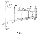
- FIG 3 is a schematic illustration in cross- section of the embodiment of the valve stem shown in Figures 1 and 2 and having 6 portions. Referring to the drawings, in Figures 1, 2, and 3, for each labeled part of the valve stem 10, there is a corresponding part which is shown but which is not labeled in each cross-sectional view.
- valve stem 10 shown located within valve housing 12.
- Valve stem 10 has a coil end 14 and a muzzle end 16 and is made of metal.
- the center of valve stem 10 is preferably bored out from the coil end 14 almost through to muzzle end 16, so as to leave a hollow space 18, thereby reducing the mass of the valve and permitting faster speeds.
- Valve stem 10 as shown in Figure 1 and as more clearly shown and labeled in Figure 3 preferably has six segments, each segment of which has a particular largest diameter, as described below.
- the six portions of valve stem 10 are first portion 20, second portion 22, third portion 24, fourth portion 26, fifth portion 28, and sixth portion 30, all of which are continuously connected together and machined from one piece of metal.
- Valve housing 12 has three portions, first portion 32, second portion 34, and third portion 36, formed preferably from three pieces of metal which are shaped and bolted together so as to form one structure.
- Valve housing 12 has a hollow portion therein (not shown), within which valve stem 10 reciprocates.
- the shape of the hollow portion in valve housing 12 is substantially the same as the shape of valve stem 10, except that valve stem 10 is slightly smaller than the hollow portion, there are spaces in the hollow portion into which valve stem 10 can move as it reciprocates, and the hollow portion is in open communication with a space external to the valve (for example, a vacuum vessel) at muzzle 38 when the valve is open.
- There are five' spaces (shown as blanks in Figure 1) corresponding to one less than the number of portions of valve stem 10.
- muzzle end 16 of valve stem 10 moves into muzzle 38; third portion 24 moves into gas reservoir 40; fourth portion 26 moves into third space 42; fifth portion 28 moves into sealed air chamber 44; and sixth portion 30 moves into fifth space 46.
- seal retainers 48 and 50 Located around the circumference of gas reservoir 40 and between front seal 52 and rear seal 54 are seal retainers 48 and 50. These retainers hold front seal 52 and rear seal 54 in their respective positions and they form the walls of gas reservoir 40.
- first seal 56 and second seal 58 which are preferably O-rings, each of which is located within a small groove cut into valve housing 12. These grooves serve to prevent first seal 56 and second seal 58 from being displaced to an appreciable extent as the valve stem 10 reciprocates.
- Gas inlet 60 is preferably continuously in open communication with a pressurized gas source (not shown) which feeds pressurized gas into gas reservoir 40 through conduit 61.
- Preferred actuating means pancake coil 62 is held in a fixed position by means of dovetail grooves 63 within third portion 36 of valve housing 12.
- Third portion 36 of valve housing 12 houses a cylinder 64 made of an insulator which is preferably machined fiberglass.
- Cylinder 64 houses solid metal rod 65, having a bore in one end, into which a high voltage connection is connected by means of a plug such as a banana plug 66.
- Cylinder 64 is slotted (not shown) at the end near valve stem 10.
- One end of the flattened wire forming the turns of the pancake coil is soldered into a slit in solid metal rod 65, and the wire is next passed through the slot in cylinder 64.
- Cylinder 64 extends beyond the usual boundary of third portion 36; and that extending portion is housed within extending housing 70, which is preferably made of molded fiberglass and epoxy. Extending housing 70 is housed within hollow outer housing 72, which is connected to third portion 36 by screws (not shown). Extending housing 70 is connected by means of dovetail grooves 71 to third portion 36.
- High voltage connection (not shown) is the inner conducting portion of coaxial cable 74 and is located within insulator 67; the outer conducting portion is terminal 76.
- Coaxial cable 74 should be grounded.
- Solid metal rod 65 is threaded to take nut 78.
- Solid metal rod 65 continues through cylinder 64 and it (as well as the slotted end of cylinder 64) is covered by fiberglass (not shown), over which a removable thin sheet of insulator such as Mylar R (not shown) is fitted so as to cover all of the turns of the coil, solid metal rod 65, and cylinder 64 when the valve is assembled.
- a nut 78 is positioned on the end of solid metal rod 65 near terminal 76. When nut 78 is tightened, cylinder 64 is maintained in its position.
- Clamp 80 is used to clamp terminal 76 onto hollow outer housing 72.
- Coaxial cable 74 is connected to any source of changing current suitable for actuating the valve stem 10.
- Seals 82 are positioned along the boundary between second portion 34 and first portion 32 of valve housing 12. Seals 84 are positioned around front seal 52 and rear seal 54.
- valve stem 10 a cross section of valve stem 10 is schematically shown, without showing hollow space 18.
- the six portions of valve stem 10, further described below, are labeled in Figure 3.
- these portions are tapered as shown. This tapering is particularly important for sixth portion 30.
- Shown in dotted lines (for purposes of orientation) are fifth space 46, sealed air chamber 44, third space 42, rear seal 54, and front seal 52.
- the largest diameter of first portion 20 of valve stem 10 is a; of second portion 22, b; of third portion 24, c; of fourth portion 26, d; of fifth portion 28, e; and of sixth portion 30, f.
- valve The operation of the valve is the following. Initially the valve is in its closed position, as shown in Figure 1; and no current flows in pancake coil 62.
- the pressurized gas located within gas reservoir 40 exerts an axial force on front seal 52 when the valve is closed.
- front seal 52 exerts a radial force on muzzle end 16 of valve body 10 so as to prevent escape of gas from the valve when the valve is in its closed position.
- a pulse of current is sent through pancake coil 62, the pulse being preferably a half sine wave pulse so that there is no residual current to retard the return speed; and the changing magnetic field sets up an induced current in coil end 14 of valve stem 10.
- the induced current interacts with the magnetic field, and valve stem 10 is forced away from pancake coil 62; and the valve begins to open.
- Pressurized gas located in gas reservoir 40 then flows out through the space which has opened between muzzle end 16 and front seal 52.
- the valve begins to open at the same time that valve stem 10 is moving at its maximum velocity. This is achieved by the choice of the dimensions of stem 10 and seal 52 for a particular force applied to valve stem 10 by coil 62. It has been found that the impulse applied to the coil end of the stem causes axial compression of the stem and the stem actually is deformed at space 46. When the muzzle end of the stem reaches its maximum velocity, it has moved a' distance g (shown in Figure 3).
- valve stem 10 After valve stem 10 has reached its maximum velocity, it moves at nearly its maximum velocity for a short time and then begins to slow down because of two features in the valve.
- the air (now compressed) within sealed air chamber 44 operates to slow down the valve stem, as does the feature (further described below) that c be greater than a.
- the action of sealed air chamber 44 performs two related functions; i.e., it provides a highly nonlinear cushioning element which stops the forward motion of the valve stem 10 without damage to the valve body and it provides a restoring force to return the valve stem to its closed position.
- at least one sealed air chamber 44 is required.
- the sealing can be done by seals located so that one seal is on either side of the air chamber between valve stem 10 and valve housing 12.
- sealed air chamber 44 The operation of sealed air chamber 44 is approximately described by the equation wherein F is the retarding force of the air chamber, wherein P o is the chamber fill pressure, A is the cross-sectional area of the chamber, q is the maximum stroke length, x is the distance traveled by the valve stem, and k is the ratio of specific heat at constant pressure to that at constant volume of the gas in the chamber.
- P o is atmospheric pressure when the air chamber is filled with air at atmospheric pressure
- k is 1.4 (assuming ideal gas laws, which provide a rough approximation).
- valve stem In the apparatus of the invention, to achieve proper seating of the valve in its fully closed position without using a spring, it is required that the valve stem have a shape such that when the valve is in an open (i.e., fully or partially open) position, gas is released from the gas reservoir to a space external to the valve so as to exert a force on the valve stem tending to restore the valve to its fully closed position.
- a is greater than b and c is greater than a (where a, b, and c are shown in Figure 3).
- c is greater than a, the component of the surface area vector lying parallel to the axis of the valve stem will be larger for third portion 24 than for first portion 20.
- valve stem 10 comprises six portions as shown in Figure 3. There must, however, be enough portions to form at least one air cushion space and to provide the structure on which the restoring force acts at the muzzle end (as described above).
- Front seal 52 and rear seal 54 can be formed from any material which exerts a radial force when it is stressed in the axial direction. For example, Teflon R can be used.
- any suitable actuating means can be used to actuate the valve.
- the actuating means employs a source of electrical current, it is required that the electrical source be such that it gives rise to a changing magnetic field, which induces the current that causes the valve stem to be accelerated and to open the valve.
- the coil end 14 of the valve stem must be made of metal. Any current pulse having an amplitude which is approximately zero when the valve is to begin to close can be used, although a half sine wave pulse was used in the example below and is preferred.
- the actuating means is a pancake coil formed from flattened copper wire, using fiberglass as insulation between the turns.
- the copper wire is preferably glued onto a similarly shaped strip of fiberglass, and one end of the wire is soldered to metal rod 65.
- the wire is tightly wound around the rod, so as to maximize the number of turns in the area occupied by the coil.
- Fiberglass is next placed on top of and below the formed coil for insulation. Then, the coil is inserted into third portion 36 of valve housing 12; and the loose end of the wire is clamped by a set screw into third portion 36. The formed coil is then impregnated with epoxy.
- valve stem In orderto optimize the speed of the valve stem, its mass should be small.
- the valve stem will be hollow and will be made of an alloy of aluminum or of some other strong but lightweight metal.
- the cross-sectional area of the coil end will be large as compared with other sections of the valve stem; and the number of turns in the coil area will be maximized.
- the externally applied gas pressure can be increased; and the quantity c can be increased with respect to the quantity a.
- the fill pressure P o can be increased and the piston area A can be increased.
- the externally applied gas pressure used for closing the valve is continuously in open communication with the source of that pressurized gas.
- the pressurized gas could be turned on only during the period of time of closing of the valve.
- more than one sealed air cushion space can be employed in the valve; and, if desired, a plurality of valves can be operated simultaneously to fill a theta pinch vacuum vessel, for example.
- a valve having the design shown in Figures 1, 2, and 3 was constructed.
- the valve stem and valve housing were made of an aluminum alloy comprising 97.9% aluminum and normal impurities, 0.6% silicon, 0.25% copper, 1.0% magnesium, and 0.25% chromium.
- the valve was operated in cooperation with a pancake coil, which was made as described above.
- the valve stem had a mass of 50 grams, a maximum stem travel of 4 millimeters, and a cross-sectional area of the coil end 14 of 20.3 cm 2 .
- the pancake coil had 30 turns.
- the applied current was approximately half sine wave pulses of approximately 70 psec duration, with a maximum of 5300 amps.
- the applied pressure used in closing the valve was 1400 psi.
- the maximum speed of the valve operated under these conditions was measured to be about 18 m/ sec, and the valve was used for 3000 shots without any apparent damage. Additionally, it is noted that the volume occupied by the valve housing was only about 2100 cc and the volume occupied by the valve stem was only about 18.5 cc. The ratio of volumes was thus only about 115.
- This valve was used to produce puffs of gas which were used to fill a theta pinch vacuum vessel.
- the opening time (i.e., time from start of current to the time at maximum valve opening) of the valve was 150 psec
- the closing time i.e. the time from maximum opening to time at cessation of gas flow
- the overall time during which any gas flowed out of the valve was less than 250 ⁇ sec (as estimated by the characteristics of the gas puff emitted by the valve).
Landscapes
- Engineering & Computer Science (AREA)
- General Engineering & Computer Science (AREA)
- Mechanical Engineering (AREA)
- Lift Valve (AREA)
Claims (9)
Applications Claiming Priority (2)
| Application Number | Priority Date | Filing Date | Title |
|---|---|---|---|
| US06/150,393 US4344449A (en) | 1980-05-16 | 1980-05-16 | Fast-acting valve and uses thereof |
| US150393 | 1980-05-16 |
Publications (3)
| Publication Number | Publication Date |
|---|---|
| EP0053622A1 EP0053622A1 (de) | 1982-06-16 |
| EP0053622A4 EP0053622A4 (de) | 1982-09-03 |
| EP0053622B1 true EP0053622B1 (de) | 1986-11-26 |
Family
ID=22534319
Family Applications (1)
| Application Number | Title | Priority Date | Filing Date |
|---|---|---|---|
| EP19810901652 Expired EP0053622B1 (de) | 1980-05-16 | 1981-05-14 | Schnellschlussventil und seine verwendung |
Country Status (4)
| Country | Link |
|---|---|
| US (1) | US4344449A (de) |
| EP (1) | EP0053622B1 (de) |
| CA (1) | CA1149362A (de) |
| WO (1) | WO1981003371A1 (de) |
Families Citing this family (12)
| Publication number | Priority date | Publication date | Assignee | Title |
|---|---|---|---|---|
| NZ202903A (en) * | 1981-12-29 | 1988-01-08 | Hoechst Ag | 1-- pe pyrrol-2-yl-carboxylic acid derivatives and pharmaceutical compositions |
| DE3328467A1 (de) * | 1983-08-06 | 1985-02-21 | Robert Bosch Gmbh, 7000 Stuttgart | Elektromagnetisch betaetigbares ventil |
| US4497298A (en) * | 1984-03-08 | 1985-02-05 | General Motors Corporation | Diesel fuel injection pump with solenoid controlled low-bounce valve |
| US4635855A (en) * | 1985-04-26 | 1987-01-13 | At&T Technologies, Inc. | Method and apparatus for rapidly controlling the flow of gas |
| US4966193A (en) * | 1990-01-30 | 1990-10-30 | Allied-Signal Inc. | Timing control for a dual poppet valve |
| US5144982A (en) * | 1990-10-12 | 1992-09-08 | Milliken Research Corporation | Electro-pneumatic valve card assemblies |
| US5193781A (en) * | 1990-10-12 | 1993-03-16 | Milliken Research Corporation | Electro-pneumatic valve card assemblies |
| US5538770A (en) * | 1994-11-18 | 1996-07-23 | W. R. Grace & Co. -Conn. | Vinylidene chloride film with controlled gas permeability |
| US6619322B1 (en) | 2000-07-27 | 2003-09-16 | The United States Of America As Represented By The Administrator Of The National Aeronautics And Space Administration | Fast-acting valve |
| ITMI20020385A1 (it) * | 2002-02-27 | 2003-08-27 | Fonderie Dellatorre S R L | Rubinetto in alluminio fuso ed uso di una lega di alluminio per la realizzazione dello stesso |
| DE10231337B3 (de) * | 2002-07-11 | 2004-03-11 | Forschungszentrum Jülich GmbH | Schnelles magnetfeldunempfindliches Gaseinlaßventil |
| JP2010538221A (ja) * | 2007-09-07 | 2010-12-09 | マイクロシス・テクノロジーズ,インコーポレーテッド | 高速開放および高速ガス流が可能なガスバルブ |
Citations (1)
| Publication number | Priority date | Publication date | Assignee | Title |
|---|---|---|---|---|
| GB1214685A (en) * | 1967-03-06 | 1970-12-02 | Euratom | Quick-opening electromagnetic valve |
Family Cites Families (13)
| Publication number | Priority date | Publication date | Assignee | Title |
|---|---|---|---|---|
| US2431437A (en) * | 1944-05-01 | 1947-11-25 | Adel Prec Products Corp | Valve |
| US2436992A (en) * | 1944-06-16 | 1948-03-02 | Hpm Dev Corp | Solenoid with plunger |
| US2791238A (en) * | 1952-05-19 | 1957-05-07 | Walworth Co | Valve construction |
| US2851055A (en) * | 1953-03-26 | 1958-09-09 | Schulz Tool & Mfg Co | Fluid control valve |
| US2702049A (en) * | 1954-02-16 | 1955-02-15 | Taylor Winfield Corp | Fluid valve |
| US2868494A (en) * | 1954-08-26 | 1959-01-13 | United Aircraft Corp | Anti-vibrating solenoid valve |
| US3144047A (en) * | 1961-12-19 | 1964-08-11 | Koontz Wagner Electric Company | Solenoid operated valve |
| US3368791A (en) * | 1964-07-14 | 1968-02-13 | Marotta Valve Corp | Valve with magnetic actuator |
| US3358964A (en) * | 1964-12-16 | 1967-12-19 | Donald M Cohen | Seat assembly for balanced pressure reducing valve |
| US3244192A (en) * | 1965-05-19 | 1966-04-05 | Woodford Mfg Company | Valve assembly for a hydrant |
| AT288784B (de) * | 1966-10-20 | 1971-03-25 | Bosch Gmbh Robert | Elektromagnetisch betätigtes Kraftstoff-Einspritzventil für Brennkraftmaschinen |
| US3949964A (en) * | 1975-02-13 | 1976-04-13 | Westinghouse Electric Corporation | Electromechanically-operated valve |
| US4081141A (en) * | 1976-09-27 | 1978-03-28 | Almo Manifold And Tool Company | Spray bars for metal rolling and flow control valves |
-
1980
- 1980-05-16 US US06/150,393 patent/US4344449A/en not_active Expired - Lifetime
-
1981
- 1981-05-14 EP EP19810901652 patent/EP0053622B1/de not_active Expired
- 1981-05-14 WO PCT/US1981/000672 patent/WO1981003371A1/en not_active Ceased
- 1981-05-15 CA CA000377686A patent/CA1149362A/en not_active Expired
Patent Citations (1)
| Publication number | Priority date | Publication date | Assignee | Title |
|---|---|---|---|---|
| GB1214685A (en) * | 1967-03-06 | 1970-12-02 | Euratom | Quick-opening electromagnetic valve |
Also Published As
| Publication number | Publication date |
|---|---|
| EP0053622A4 (de) | 1982-09-03 |
| US4344449A (en) | 1982-08-17 |
| CA1149362A (en) | 1983-07-05 |
| WO1981003371A1 (en) | 1981-11-26 |
| EP0053622A1 (de) | 1982-06-16 |
Similar Documents
| Publication | Publication Date | Title |
|---|---|---|
| US4344449A (en) | Fast-acting valve and uses thereof | |
| US4766405A (en) | Dynamic energy absorber | |
| US2934090A (en) | Three-way magnetic valve | |
| US4546795A (en) | Solenoid valve | |
| US3126789A (en) | Hypervelocity propulsion arrangement | |
| US4761118A (en) | Positive displacement hydraulic-drive reciprocating compressor | |
| US7566206B2 (en) | Linear compressor for multi-stage compression | |
| US4525695A (en) | Force motor with ball mounted armature | |
| US2436992A (en) | Solenoid with plunger | |
| DE69324999D1 (de) | Dämpfungsvorrichtung eines Hahns | |
| US4449691A (en) | Electromagnet | |
| GB2277450A (en) | Shock wave lithotrite | |
| US3381250A (en) | Electromagnetic device | |
| US3939816A (en) | Gas filled coaxial accelerator with compression coil | |
| US5385136A (en) | Impulse stabilizer capable of asymmetrical response | |
| GB2098007A (en) | Electrical generators | |
| US3166692A (en) | Alternating current solenoid | |
| DE69108945T2 (de) | Seismische Luftkanone. | |
| US6116144A (en) | Pressure motor for electro-rheological fluids | |
| Lowder et al. | Fast gas valve for plasma research | |
| US3166684A (en) | Hydraulically actuated piezoelectric voltage generator | |
| US4682309A (en) | Device for generating acoustic pulses by implosion, inside a well | |
| US3343490A (en) | Ordinance firing device | |
| US4379680A (en) | Ambient air timing device | |
| US4268733A (en) | Liquid SF6 puffer type circuit interrupter |
Legal Events
| Date | Code | Title | Description |
|---|---|---|---|
| PUAI | Public reference made under article 153(3) epc to a published international application that has entered the european phase |
Free format text: ORIGINAL CODE: 0009012 |
|
| AK | Designated contracting states |
Designated state(s): DE FR |
|
| 17P | Request for examination filed |
Effective date: 19820526 |
|
| GRAA | (expected) grant |
Free format text: ORIGINAL CODE: 0009210 |
|
| AK | Designated contracting states |
Kind code of ref document: B1 Designated state(s): DE FR |
|
| ET | Fr: translation filed | ||
| REF | Corresponds to: |
Ref document number: 3175664 Country of ref document: DE Date of ref document: 19870115 |
|
| PLBE | No opposition filed within time limit |
Free format text: ORIGINAL CODE: 0009261 |
|
| STAA | Information on the status of an ep patent application or granted ep patent |
Free format text: STATUS: NO OPPOSITION FILED WITHIN TIME LIMIT |
|
| 26N | No opposition filed | ||
| PGFP | Annual fee paid to national office [announced via postgrant information from national office to epo] |
Ref country code: FR Payment date: 19900521 Year of fee payment: 10 |
|
| PGFP | Annual fee paid to national office [announced via postgrant information from national office to epo] |
Ref country code: DE Payment date: 19900525 Year of fee payment: 10 |
|
| PG25 | Lapsed in a contracting state [announced via postgrant information from national office to epo] |
Ref country code: FR Effective date: 19920131 |
|
| PG25 | Lapsed in a contracting state [announced via postgrant information from national office to epo] |
Ref country code: DE Effective date: 19920303 |
|
| REG | Reference to a national code |
Ref country code: FR Ref legal event code: ST |