EP0053523A1 - Cooking apparatus - Google Patents
Cooking apparatus Download PDFInfo
- Publication number
- EP0053523A1 EP0053523A1 EP81305717A EP81305717A EP0053523A1 EP 0053523 A1 EP0053523 A1 EP 0053523A1 EP 81305717 A EP81305717 A EP 81305717A EP 81305717 A EP81305717 A EP 81305717A EP 0053523 A1 EP0053523 A1 EP 0053523A1
- Authority
- EP
- European Patent Office
- Prior art keywords
- cooking
- cassette tape
- reference level
- oven
- microwave
- Prior art date
- Legal status (The legal status is an assumption and is not a legal conclusion. Google has not performed a legal analysis and makes no representation as to the accuracy of the status listed.)
- Granted
Links
- 238000010411 cooking Methods 0.000 title claims abstract description 91
- 239000000654 additive Substances 0.000 claims description 15
- 230000000996 additive effect Effects 0.000 claims description 15
- 238000001514 detection method Methods 0.000 claims description 14
- 230000004044 response Effects 0.000 claims description 9
- 230000006870 function Effects 0.000 description 4
- 238000010276 construction Methods 0.000 description 3
- 238000010586 diagram Methods 0.000 description 3
- 238000000034 method Methods 0.000 description 3
- 238000001816 cooling Methods 0.000 description 2
- 230000004048 modification Effects 0.000 description 2
- 238000012986 modification Methods 0.000 description 2
- 241000005398 Figaro Species 0.000 description 1
- 230000003213 activating effect Effects 0.000 description 1
- 230000000994 depressogenic effect Effects 0.000 description 1
- 230000000977 initiatory effect Effects 0.000 description 1
Images


Classifications
-
- H—ELECTRICITY
- H05—ELECTRIC TECHNIQUES NOT OTHERWISE PROVIDED FOR
- H05B—ELECTRIC HEATING; ELECTRIC LIGHT SOURCES NOT OTHERWISE PROVIDED FOR; CIRCUIT ARRANGEMENTS FOR ELECTRIC LIGHT SOURCES, IN GENERAL
- H05B6/00—Heating by electric, magnetic or electromagnetic fields
- H05B6/64—Heating using microwaves
- H05B6/6435—Aspects relating to the user interface of the microwave heating apparatus
- H05B6/6438—Aspects relating to the user interface of the microwave heating apparatus allowing the recording of a program of operation of the microwave heating apparatus
-
- H—ELECTRICITY
- H05—ELECTRIC TECHNIQUES NOT OTHERWISE PROVIDED FOR
- H05B—ELECTRIC HEATING; ELECTRIC LIGHT SOURCES NOT OTHERWISE PROVIDED FOR; CIRCUIT ARRANGEMENTS FOR ELECTRIC LIGHT SOURCES, IN GENERAL
- H05B6/00—Heating by electric, magnetic or electromagnetic fields
- H05B6/64—Heating using microwaves
- H05B6/6447—Method of operation or details of the microwave heating apparatus related to the use of detectors or sensors
- H05B6/6458—Method of operation or details of the microwave heating apparatus related to the use of detectors or sensors using humidity or vapor sensors
-
- H—ELECTRICITY
- H05—ELECTRIC TECHNIQUES NOT OTHERWISE PROVIDED FOR
- H05B—ELECTRIC HEATING; ELECTRIC LIGHT SOURCES NOT OTHERWISE PROVIDED FOR; CIRCUIT ARRANGEMENTS FOR ELECTRIC LIGHT SOURCES, IN GENERAL
- H05B6/00—Heating by electric, magnetic or electromagnetic fields
- H05B6/64—Heating using microwaves
- H05B6/647—Aspects related to microwave heating combined with other heating techniques
- H05B6/6482—Aspects related to microwave heating combined with other heating techniques combined with radiant heating, e.g. infrared heating
Definitions
- the present invention relates to a cooking apparatus including a gas sensor having an output which is used to automatically control a cooking operation.
- a gas sensor element having a resistance value which changes in response to the cooking condition of foodstuff disposed in a cooking apparatus has been developed.
- a microwave oven including a gas sensor element is described in our U.K. Patent Application No. 7930612, "COOKING UTENSIL CONTROLLED BY GAS SENSOR OUTPUT", published on August 28, 1980, the publication number being 2,040,502A.
- the cooking sequence program is stored in a microcomputer system included in the microwave oven and, therefore, only a limited number of automatic cooking operations are performed. It was difficult to determine a suitable cooking constant, which determines the completion of cooking in combination with the output signal derived from the gas sensor element, for each of the various kinds of cooking operation.
- a cooking apparatus which includes a cassette tape player system for audibly announcing an explanation concerning cooking.
- a microwave oven having a cassette tape player system is described in our copending European Patent Application No. 80303308.3, "CASSETTE TAPE CONTROLLED COOKING APPARATUS",' published on April 1, 1981, the publication number being 0.026,094 A2.
- the cassette tape carries digital data for controlling the cooking operation in addition to the audio information for providing the audible announcement of an explanation concerning cooking.
- the digital data includes time data for determining a cooking time period.
- a cooking apparatus which has a control responsive to reproduced data relating to a cooking program for controlling the cooking apparatus has a gas sensor the output of which is compared with a reference level determined by the reproduced data, the control being operable to terminate a cooking operation when the reference level has been reached.
- a cassette tape player system is included in a combination microwave and electric heater oven.
- a gas sensor is disposed in the combination microwave and electric heater oven for detecting the cooking condition of a foodstuff disposed in the combination microwave and electric heater oven.
- the cassette tape carries a digital data related to a cooking constant which determines the cooking completion condition for each of the cooking operation.
- the cooking constant data read by the cassette tape player system is stored in a control system included in the combination microwave and electric heater oven.
- the cooking constant data is used to obtain a reference level indicating the cooking completion condition, which is compared with an output signal derived from the gas sensor, whereby a cooking completion instruction signal is developed from the control system when the output signal derived from the gas sensor reaches the reference level.
- a combination microwave and electric heater oven of the present invention comprises a housing 1 and an oven cavity 2 surrounded by oven walls.
- a sheath heater 3 is disposed in the oven cavity 2 for grilling the foodstuff, and a magnetron 4 is secured to the oven wall for microwave cooking purposes.
- the microwave energy generated by the magnetron 4 is supplied to the oven cavity 2 through a waveguide 5.
- a power supply circuit comprising a high voltage transformer 6 and a condenser 7 is secured to the housing 1 for supplying the power to the magnetron 4.
- a blower fan motor 8 is associated with a blower fan 9 which functions to cool the magnetron 4.
- the control panel 11 includes a keyboard panel 12, 'a digital display unit 13, a cassette tape inlet 14 for accommodating a cassette tape 15, and a heater position control knob 40 for adjusting the heater location in the oven cavity 2.
- the keyboard panel 12 is to introduce numeral information such as a set temperature and a set cook time period, and cooking commands. That is, the keyboard panel 12 is an input unit for performing the digital controlled cooking operation.
- a typical construction of the digital controlled microwave oven is disclosed in U.S. Patent No. 4,255,639, "MICROWAVE OVEN WITH A PROGRAMMABLE DIGITAL CONTROL CIRCUIT", issued on March 10, 1981.
- the heater position control knob 40 is to select the heater height between "High”, “Middle” and “Low".
- a typical construction for shifting the heater location in the oven cavity is shown and described in U.S. Patent No. 4,137,442, "HIGH-FREQUENCY OVEN HAVING A BROWNING UNIT", issued on Jan. 30, 1979.
- a cassette tape player system 18 is disposed to confront the cassette tape inlet 14.
- the cassette tape player system 18 comprises a tape drive motor 16, and two magnetic reproduction heads 17a and 17 b .
- a printed circuit board 19 is disposed behind the keyboard panel 12 for supporting the control circuit of the combination microwave and electric heater oven.
- First and second relays 20 and 21 are connected to the control circuit for controlling the operation of the magnetron 4 and the sheath heater 3, respectively.
- a speaker system 24 is associated with the cassette tape player system 18 for providing an audible explanation derived from the cassette tape player system 18. More specifically, cooking explanations are recorded on the cassette tape 15, and the tape drive motor 16 drives the cassette tape 15 at a desired timing for generating the audible explanation.
- FIGURE 3 schematically shows a control system of the combination microwave and electric heater oven of the present invention. Like elements corresponding to those of FIGURES 1 and 2 are indicated by like numerals.
- a capstan 25 is connected to the tape drive motor 16.
- a pinch roller 26 is depressed toward the capstan 25, a magnetic tape 15a is driven to travel in the direction shown by arrows in FIGURE 3 for reproduction purposes.
- the two magnetic reproduction heads 17a and 17 b are made contact with two tracks recorded on the magnetic tape 15a, respectively, for reproducing recorded information.
- FIGURE 4 shows recording tracks on the magnetic tape 15a.
- a first track 151 and a second track 152 are assigned to the forward direction drive, and a third track 153 and a fourth track 154 are assigned to the reverse direction drive.
- audio information is recorded through the use of the analog recording technique for providing an audible cooking explanation.
- digital information is recorded through the use of the saturation recording technique such as the phase encoding technique for providing a digital data which controls the cooking operation performed by the combination microwave and electric heater oven.
- the magnetic reproduction head 17 a contacts the first track 151 or the fourth track 154.
- the audio information output reproduced from the magnetic reproduction head 17 a is applied to an audio amplifier 27 for activating the speaker system 24.
- the magnetic reproduction head 17 b contacts the second track 152 or the third track 153.
- the digital information output derived from the magnetic reproduction head 17 b is introduced into a read-out amplifier 28, whereby the digital information output is converted into a binary code signal and applied to a digital control system 29.
- the digital control system 29 comprises a central processor unit 291, a read only memory 292 and a random access memory 293.
- the binary code signal applied to the digital control system 29 is processed in the digital control system 29, thereby providing a control signal for controlling the operation of the combination microwave and electric heater oven in accordance with a preselected program sequence.
- a motor driver circuit 30 is associated with the digital control system 29 for driving the tape drive motor 16 at a desired timing. More specifically, the digital control system 29 develops a start signal for initiating the rotation of the tape drive motor 16, and a stop signal for terminating the rotation of the tape drive motor 16.
- a display driver circuit 31 is associated with the digital control system 29 for driving the digital display unit 13 in accordance with the digital display data derived from the magnetic reproduction head 17 b . More specifically, the digital display unit 13 is adopted to display the programmed cooking period or the programmed cooking condition in a digital fashion.
- a buzzer driver circuit 32 and a buzzer 33 are associated with the digital control system 29.
- a tape start button 34 is disposed on the control panel 11 for controlling the cassette tape drive.
- the start signal is developed from the digital control system 29.
- the first relay 20 is associated with a first control switch 35 which is disposed between the high voltage transformer 6 and an AC power source 37.
- the high voltage transformer 6 functions, in combination with the condenser 7 and a diode 38, to energize the magnetron 4.
- the second relay 21 is associated with a second control switch 36 which is disposed between the sheath heater 3 and the AC power source 37.
- the relays 20 and 21 are controlled by control signals developed from the digital control system 29.
- the combination microwave and electric heater oven of the present invention further comprises a gas sensor 42 of which a resistance value changes in response to the concentration of the gas developed from the foodstuff disposed in the combination microwave and electric heater oven.
- a preferred gas sensor is "TGS 14813" manufactured by Figaro Engineering Inc.
- a detection characteristic of the gas sensor 42 is described in the above copending U.K. Patent Application No. 7930612 (publication No. 2040502A).
- the gas sensor 42 is connected to a resistance-to-frequency converter 43 implemented with an astable multivibrator.
- the frequency of an output signal derived from the resistance-to-frequency converter 43 changes in response to the variation of the resistance value of the gas sensor 42.
- a preferred circuit construction of the combination of the gas sensor 42 and the resistance-to-frequency converter 43 is described in our copending U.K. Patent Application No. 8123276 "SENSOR CONTROLLED COOKING APPARATUS", filed on July 28, 1981, a copy of which is being forwarded herewith to the European Patent Office.
- the digital information recorded on the second and third tracks 152 and 153 includes a cooking program data for determining the cooking sequence, the cooking time period, the cooking heat source, etc., and, in addition to that, a cooking constant data which is used to determine a reference level which is compared with the output signal derived from the resistance-to-frequency converter 43.
- the cooking constant is a particular value determined for each of the plural kinds of cooking operation.
- FIGURE 5 shows an essential part of the digital control system 29.
- FIGURE 5 only shows the digital control system related to the automatic microwave cooking operation controlled by the output signal derived from the gas sensor 42.
- the digital control system 29 comprises a main processor 50 and a subprocessor 90.
- the subprocessor 90 controls the drive of the cassette tape player system 18 and the read out operation of the digital data recorded on the cassette tape 15. More specifically, the subprocessor 90 includes a first detection unit 92 for reading out a cooking constant A, a second detection unit 94 for reading out an additive cooking coefficient N, a first power detection unit 96 for reading out a microwave power data in the main cooking operation, and a second power detection unit 98 for reading out a microwave power data in an additive cooking operation.
- the main processor 50 comprises a first comparactor 52 which functions to compare the output signal derived from the resistance-to-frequency converter 43 with a reference level determined in the main processor 50 and to develop a first control signal when the output signal frequency of the resistance-to-frequency converter 43 reaches the reference level.
- a second comparator 54 is included in the main processor 50, which develops a second control signal when the additive cooking operation is performed for a preselected period of time.
- the combination microwave and electric heater oven is first placed in a cooling period t 0 .
- the gas sensor 42 detects the concentration of the gas within the oven cavity.
- the frequency of the output signal developed from the resistance-to-frequency converter 43 varies as shown in FIGURE 6 in response to the variation of the detected gas concentration.
- the main processor 50 includes a minimum frequency memory 56 for storing a minimum frequency F 0 during the cooling period t 0 .
- a detection frequency F derived from the resistance-to-frequency converter 43 varies in response to the detected gas concentration.
- the cooking constant A recorded on the cassette tape 15 and read out by the first detection unit 92 included in the subprocessor 90 is introduced into a reference level calculation unit 58 included in the main processor 50.
- the reference level calculation unit 58 calculates a reference level A ⁇ F 0 through the use of the minimum frequency F 0 obtained in the minimum frequency memory 56.
- the thus obtained reference level A ⁇ F 0 is introduced into and stored in a reference level memory 60 included in the main processor 50.
- the microwave cooking is conducted at the microwave power determined by the first power detection unit 96.
- the detection frequency F 1 detected by an output frequency detection unit 62 reaches the reference level A ⁇ F 0 contained in the reference level memory 60
- the first comparactor 52 develops the first control signal toward a cooking control signal generator 64 in order to terminate the main cooking.
- a period counter 66 and a timepiece 68 are included in the main processor 50 for detecting a main cooking period T 1 .
- the combination microwave and electric heater oven of the present invention is constructed to conduct an additive cooking at a microwave power read by the second power detection unit 98 for a preselected period ot time T 2 .
- the main processor 50 includes an additive cooking period calculation unit 70 which functions to calculate the additive cooking period T 2 in response to the main cooking period T 1 obtaind in the period counter 66 and the additive cooking coefficient N recorded on the cassette tape 15 and read by the second detection unit 92.
- a modification factor A N is introduced, at an operator's choice, from the keyboard panel 12 into the additive cooking period calculation unit 70.
- the additive cooking period T 2 is determined in accordance with the following equation.
- the second comparator 54 develops the second control signal to terminate the additive cooking operation.
- the main processor 50 is implemented with a microprocessor "IX2058YA” manufactured by Sharp Corporation
- the subprocessor 90 is implemented with a microprocessor "IX2057YA” manufactured by Sharp Corporation.
Abstract
Description
- The present invention relates to a cooking apparatus including a gas sensor having an output which is used to automatically control a cooking operation.
- A gas sensor element having a resistance value which changes in response to the cooking condition of foodstuff disposed in a cooking apparatus has been developed. A microwave oven including a gas sensor element is described in our U.K. Patent Application No. 7930612, "COOKING UTENSIL CONTROLLED BY GAS SENSOR OUTPUT", published on August 28, 1980, the publication number being 2,040,502A.
- In the above-mentioned microwave oven, the cooking sequence program is stored in a microcomputer system included in the microwave oven and, therefore, only a limited number of automatic cooking operations are performed. It was difficult to determine a suitable cooking constant, which determines the completion of cooking in combination with the output signal derived from the gas sensor element, for each of the various kinds of cooking operation.
- On the other hand, a cooking apparatus has been developed which includes a cassette tape player system for audibly announcing an explanation concerning cooking. A microwave oven having a cassette tape player system is described in our copending European Patent Application No. 80303308.3, "CASSETTE TAPE CONTROLLED COOKING APPARATUS",' published on April 1, 1981, the publication number being 0.026,094 A2.
- In the above-mentioned cassette tape controlled microwave oven, the cassette tape carries digital data for controlling the cooking operation in addition to the audio information for providing the audible announcement of an explanation concerning cooking. The digital data includes time data for determining a cooking time period.
- According to one aspect of the invention, a cooking apparatus which has a control responsive to reproduced data relating to a cooking program for controlling the cooking apparatus has a gas sensor the output of which is compared with a reference level determined by the reproduced data, the control being operable to terminate a cooking operation when the reference level has been reached.
- In a preferred embodiment of the present invention, a cassette tape player system is included in a combination microwave and electric heater oven. A gas sensor is disposed in the combination microwave and electric heater oven for detecting the cooking condition of a foodstuff disposed in the combination microwave and electric heater oven. The cassette tape carries a digital data related to a cooking constant which determines the cooking completion condition for each of the cooking operation. The cooking constant data read by the cassette tape player system is stored in a control system included in the combination microwave and electric heater oven. The cooking constant data is used to obtain a reference level indicating the cooking completion condition, which is compared with an output signal derived from the gas sensor, whereby a cooking completion instruction signal is developed from the control system when the output signal derived from the gas sensor reaches the reference level.
- The present invention will be better understood from the detailed description given hereinbelow and the accompanying drawings which are given by way of illustration only, and thus are not limitative of the present invention and wherein:
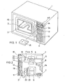
- FIGURE 1 is a perspective view of an embodiment of a combination microwave and electric heater oven of the present invention;
- FIGURE 2 is a sectional view of the combination microwave and electric heater oven of FIGURE 1;
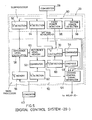
- FIGURE 3 is a block diagram of an embodiment of a control system included in the combination microwave and electric heater oven of FIGURE 1;
- FIGURE 4 is a schematic chart for explaining a recording condition on a cassette tape which is loaded on a cassette tape player system included in the combined microwave and electric heater oven of FIGURE 1;
- FIGURE 5 is a block diagram of an essential part of a digital control system included in the control system of FIGURE 3; and
- FIGURE 6 is a graph for explaining an example of operation performed by the combination microwave and electric heater oven of FIGURE 1.
- A combination microwave and electric heater oven of the present invention comprises a housing 1 and an
oven cavity 2 surrounded by oven walls. Asheath heater 3 is disposed in theoven cavity 2 for grilling the foodstuff, and amagnetron 4 is secured to the oven wall for microwave cooking purposes. The microwave energy generated by themagnetron 4 is supplied to theoven cavity 2 through awaveguide 5. A power supply circuit comprising ahigh voltage transformer 6 and acondenser 7 is secured to the housing 1 for supplying the power to themagnetron 4. Ablower fan motor 8 is associated with ablower fan 9 which functions to cool themagnetron 4. - An
oven door 10 and acontrol panel 11 are disposed at the front face of the housing 1. Thecontrol panel 11 includes akeyboard panel 12, 'adigital display unit 13, acassette tape inlet 14 for accommodating acassette tape 15, and a heaterposition control knob 40 for adjusting the heater location in theoven cavity 2. Thekeyboard panel 12 is to introduce numeral information such as a set temperature and a set cook time period, and cooking commands. That is, thekeyboard panel 12 is an input unit for performing the digital controlled cooking operation. A typical construction of the digital controlled microwave oven is disclosed in U.S. Patent No. 4,255,639, "MICROWAVE OVEN WITH A PROGRAMMABLE DIGITAL CONTROL CIRCUIT", issued on March 10, 1981. The heaterposition control knob 40 is to select the heater height between "High", "Middle" and "Low". A typical construction for shifting the heater location in the oven cavity is shown and described in U.S. Patent No. 4,137,442, "HIGH-FREQUENCY OVEN HAVING A BROWNING UNIT", issued on Jan. 30, 1979. - Behind the
control panel 11, a cassettetape player system 18 is disposed to confront thecassette tape inlet 14. The cassettetape player system 18 comprises atape drive motor 16, and twomagnetic reproduction heads 17a and 17b. A printedcircuit board 19 is disposed behind thekeyboard panel 12 for supporting the control circuit of the combination microwave and electric heater oven. First andsecond relays magnetron 4 and thesheath heater 3, respectively. Aspeaker system 24 is associated with the cassettetape player system 18 for providing an audible explanation derived from the cassettetape player system 18. More specifically, cooking explanations are recorded on thecassette tape 15, and thetape drive motor 16 drives thecassette tape 15 at a desired timing for generating the audible explanation. - FIGURE 3 schematically shows a control system of the combination microwave and electric heater oven of the present invention. Like elements corresponding to those of FIGURES 1 and 2 are indicated by like numerals.
- A
capstan 25 is connected to thetape drive motor 16. When apinch roller 26 is depressed toward thecapstan 25, amagnetic tape 15a is driven to travel in the direction shown by arrows in FIGURE 3 for reproduction purposes. The twomagnetic reproduction heads 17a and 17b are made contact with two tracks recorded on themagnetic tape 15a, respectively, for reproducing recorded information. - FIGURE 4 shows recording tracks on the
magnetic tape 15a. Afirst track 151 and asecond track 152 are assigned to the forward direction drive, and athird track 153 and afourth track 154 are assigned to the reverse direction drive. On the first andfourth tracks third tracks - The magnetic reproduction head 17 a contacts the
first track 151 or thefourth track 154. The audio information output reproduced from themagnetic reproduction head 17 a is applied to anaudio amplifier 27 for activating thespeaker system 24. The magnetic reproduction head 17b contacts thesecond track 152 or thethird track 153. The digital information output derived from the magnetic reproduction head 17b is introduced into a read-out amplifier 28, whereby the digital information output is converted into a binary code signal and applied to adigital control system 29. - The
digital control system 29 comprises acentral processor unit 291, a readonly memory 292 and arandom access memory 293. The binary code signal applied to thedigital control system 29 is processed in thedigital control system 29, thereby providing a control signal for controlling the operation of the combination microwave and electric heater oven in accordance with a preselected program sequence. Amotor driver circuit 30 is associated with thedigital control system 29 for driving thetape drive motor 16 at a desired timing. More specifically, thedigital control system 29 develops a start signal for initiating the rotation of thetape drive motor 16, and a stop signal for terminating the rotation of thetape drive motor 16. Adisplay driver circuit 31 is associated with thedigital control system 29 for driving thedigital display unit 13 in accordance with the digital display data derived from the magnetic reproduction head 17b. More specifically, thedigital display unit 13 is adopted to display the programmed cooking period or the programmed cooking condition in a digital fashion. Abuzzer driver circuit 32 and abuzzer 33 are associated with thedigital control system 29. - A
tape start button 34 is disposed on thecontrol panel 11 for controlling the cassette tape drive. When thetape start button 34 is actuated, the start signal is developed from thedigital control system 29. Thefirst relay 20 is associated with afirst control switch 35 which is disposed between thehigh voltage transformer 6 and anAC power source 37. Thehigh voltage transformer 6 functions, in combination with thecondenser 7 and adiode 38, to energize themagnetron 4. Thesecond relay 21 is associated with asecond control switch 36 which is disposed between thesheath heater 3 and theAC power source 37. Therelays digital control system 29. - The combination microwave and electric heater oven of the present invention further comprises a
gas sensor 42 of which a resistance value changes in response to the concentration of the gas developed from the foodstuff disposed in the combination microwave and electric heater oven. A preferred gas sensor is "TGS 14813" manufactured by Figaro Engineering Inc. A detection characteristic of thegas sensor 42 is described in the above copending U.K. Patent Application No. 7930612 (publication No. 2040502A). - The
gas sensor 42 is connected to a resistance-to-frequency converter 43 implemented with an astable multivibrator. The frequency of an output signal derived from the resistance-to-frequency converter 43 changes in response to the variation of the resistance value of thegas sensor 42. A preferred circuit construction of the combination of thegas sensor 42 and the resistance-to-frequency converter 43 is described in our copending U.K. Patent Application No. 8123276 "SENSOR CONTROLLED COOKING APPARATUS", filed on July 28, 1981, a copy of which is being forwarded herewith to the European Patent Office. - The digital information recorded on the second and
third tracks frequency converter 43. The cooking constant is a particular value determined for each of the plural kinds of cooking operation. - FIGURE 5 shows an essential part of the
digital control system 29. For the purpose of simplicity, FIGURE 5 only shows the digital control system related to the automatic microwave cooking operation controlled by the output signal derived from thegas sensor 42. - The
digital control system 29 comprises amain processor 50 and asubprocessor 90. Thesubprocessor 90 controls the drive of the cassettetape player system 18 and the read out operation of the digital data recorded on thecassette tape 15. More specifically, thesubprocessor 90 includes afirst detection unit 92 for reading out a cooking constant A, asecond detection unit 94 for reading out an additive cooking coefficient N, a firstpower detection unit 96 for reading out a microwave power data in the main cooking operation, and a secondpower detection unit 98 for reading out a microwave power data in an additive cooking operation. - The
main processor 50 comprises afirst comparactor 52 which functions to compare the output signal derived from the resistance-to-frequency converter 43 with a reference level determined in themain processor 50 and to develop a first control signal when the output signal frequency of the resistance-to-frequency converter 43 reaches the reference level. Asecond comparator 54 is included in themain processor 50, which develops a second control signal when the additive cooking operation is performed for a preselected period of time. - An operation mode of the
digital control system 29 will be described with reference to the FIGURE 5 block diagram and an output frequency variation shown in FIGURE 6. - When the cook start instruction is developed in the microwave cooking mode, the combination microwave and electric heater oven is first placed in a cooling period t0. The
gas sensor 42 detects the concentration of the gas within the oven cavity. The frequency of the output signal developed from the resistance-to-frequency converter 43 varies as shown in FIGURE 6 in response to the variation of the detected gas concentration. Themain processor 50 includes aminimum frequency memory 56 for storing a minimum frequency F0 during the cooling period t0. - As already discussed above, a detection frequency F derived from the resistance-to-
frequency converter 43 varies in response to the detected gas concentration. The cooking constant A recorded on thecassette tape 15 and read out by thefirst detection unit 92 included in thesubprocessor 90 is introduced into a referencelevel calculation unit 58 included in themain processor 50. The referencelevel calculation unit 58 calculates a reference level A·F0 through the use of the minimum frequency F0 obtained in theminimum frequency memory 56. The thus obtained reference level A·F0 is introduced into and stored in areference level memory 60 included in themain processor 50. - The microwave cooking is conducted at the microwave power determined by the first
power detection unit 96. When the detection frequency F1 detected by an outputfrequency detection unit 62 reaches the reference level A·F0 contained in thereference level memory 60, thefirst comparactor 52 develops the first control signal toward a cookingcontrol signal generator 64 in order to terminate the main cooking. - A
period counter 66 and atimepiece 68 are included in themain processor 50 for detecting a main cooking period T1. The combination microwave and electric heater oven of the present invention is constructed to conduct an additive cooking at a microwave power read by the secondpower detection unit 98 for a preselected period ot time T2. More specifically, themain processor 50 includes an additive cookingperiod calculation unit 70 which functions to calculate the additive cooking period T2 in response to the main cooking period T1 obtaind in theperiod counter 66 and the additive cooking coefficient N recorded on thecassette tape 15 and read by thesecond detection unit 92. In a preferred form, a modification factor A N is introduced, at an operator's choice, from thekeyboard panel 12 into the additive cookingperiod calculation unit 70. The additive cooking period T2 is determined in accordance with the following equation.
- When the additive cooking is performed for the additive cooking period T22 the
second comparator 54 develops the second control signal to terminate the additive cooking operation. - In a preferred form, the
main processor 50 is implemented with a microprocessor "IX2058YA" manufactured by Sharp Corporation, and thesubprocessor 90 is implemented with a microprocessor "IX2057YA" manufactured by Sharp Corporation. - The invention being thus described, it will be obvious that the same may be varied in many ways. Such variations are not to be regarded as a departure from the spirit and scope of the invention, and all such modifications are intended to be included within the scope of the following claims.
Claims (11)
Applications Claiming Priority (2)
| Application Number | Priority Date | Filing Date | Title |
|---|---|---|---|
| JP17165080A JPS5795528A (en) | 1980-12-03 | 1980-12-03 | Cooking apparatus |
| JP171650/80 | 1980-12-03 |
Publications (2)
| Publication Number | Publication Date |
|---|---|
| EP0053523A1 true EP0053523A1 (en) | 1982-06-09 |
| EP0053523B1 EP0053523B1 (en) | 1987-08-26 |
Family
ID=15927137
Family Applications (1)
| Application Number | Title | Priority Date | Filing Date |
|---|---|---|---|
| EP81305717A Expired EP0053523B1 (en) | 1980-12-03 | 1981-12-03 | Cooking apparatus |
Country Status (5)
| Country | Link |
|---|---|
| EP (1) | EP0053523B1 (en) |
| JP (1) | JPS5795528A (en) |
| AU (1) | AU528472B2 (en) |
| CA (1) | CA1172706A (en) |
| DE (1) | DE3176397D1 (en) |
Cited By (1)
| Publication number | Priority date | Publication date | Assignee | Title |
|---|---|---|---|---|
| EP0595569A1 (en) * | 1992-10-26 | 1994-05-04 | Kabushiki Kaisha Toshiba | Heating apparatus |
Families Citing this family (2)
| Publication number | Priority date | Publication date | Assignee | Title |
|---|---|---|---|---|
| JPS62135398U (en) * | 1986-02-19 | 1987-08-26 | ||
| DE69015876T2 (en) * | 1989-05-08 | 1995-08-10 | Matsushita Electric Ind Co Ltd | Automatic heater. |
Citations (6)
| Publication number | Priority date | Publication date | Assignee | Title |
|---|---|---|---|---|
| US3173335A (en) * | 1960-04-26 | 1965-03-16 | Wickman Ltd | Means for controlling the actions of machine tools |
| FR2053129A1 (en) * | 1969-07-24 | 1971-04-16 | Bowmar Tic Inc | |
| GB2002143A (en) * | 1977-07-27 | 1979-02-14 | Matsushita Electric Ind Co Ltd | Electric home appliances |
| EP0000957A1 (en) * | 1977-08-30 | 1979-03-07 | Litton Systems, Inc. | Humidity controlled microwave oven and method of cooking |
| GB2026726A (en) * | 1978-06-28 | 1980-02-06 | Tokyo Shibaura Electric Co | High frequency heating apparatus |
| EP0017749A1 (en) * | 1979-04-19 | 1980-10-29 | Dorina Nähmaschinen GmbH | Sewing machine |
Family Cites Families (6)
| Publication number | Priority date | Publication date | Assignee | Title |
|---|---|---|---|---|
| GB1545918A (en) * | 1975-05-20 | 1979-05-16 | Matsushita Electric Ind Co Ltd | Apparatus for controlling heating time utilising humidity sensing |
| JPS5388249A (en) * | 1977-01-12 | 1978-08-03 | Matsushita Electric Ind Co Ltd | Cooking equipment |
| JPS5388248A (en) * | 1977-01-12 | 1978-08-03 | Matsushita Electric Ind Co Ltd | Cooking equipment |
| JPS5613692A (en) * | 1979-07-11 | 1981-02-10 | Matsushita Electric Ind Co Ltd | High frequency heater |
| DE3066585D1 (en) * | 1979-07-20 | 1984-03-22 | Matsushita Electric Ind Co Ltd | Method of food heating control and apparatus therefor |
| DE3066593D1 (en) * | 1979-08-17 | 1984-03-22 | Matsushita Electric Ind Co Ltd | Heating apparatus with sensor |
-
1980
- 1980-12-03 JP JP17165080A patent/JPS5795528A/en active Pending
-
1981
- 1981-11-26 CA CA000390979A patent/CA1172706A/en not_active Expired
- 1981-12-01 AU AU78126/81A patent/AU528472B2/en not_active Ceased
- 1981-12-03 DE DE8181305717T patent/DE3176397D1/en not_active Expired
- 1981-12-03 EP EP81305717A patent/EP0053523B1/en not_active Expired
Patent Citations (7)
| Publication number | Priority date | Publication date | Assignee | Title |
|---|---|---|---|---|
| US3173335A (en) * | 1960-04-26 | 1965-03-16 | Wickman Ltd | Means for controlling the actions of machine tools |
| FR2053129A1 (en) * | 1969-07-24 | 1971-04-16 | Bowmar Tic Inc | |
| GB2002143A (en) * | 1977-07-27 | 1979-02-14 | Matsushita Electric Ind Co Ltd | Electric home appliances |
| DE2832434A1 (en) * | 1977-07-27 | 1979-02-15 | Matsushita Electric Ind Co Ltd | CONTROL DEVICE FOR ELECTRIC HOUSEHOLD APPLIANCES |
| EP0000957A1 (en) * | 1977-08-30 | 1979-03-07 | Litton Systems, Inc. | Humidity controlled microwave oven and method of cooking |
| GB2026726A (en) * | 1978-06-28 | 1980-02-06 | Tokyo Shibaura Electric Co | High frequency heating apparatus |
| EP0017749A1 (en) * | 1979-04-19 | 1980-10-29 | Dorina Nähmaschinen GmbH | Sewing machine |
Cited By (2)
| Publication number | Priority date | Publication date | Assignee | Title |
|---|---|---|---|---|
| EP0595569A1 (en) * | 1992-10-26 | 1994-05-04 | Kabushiki Kaisha Toshiba | Heating apparatus |
| US5558797A (en) * | 1992-10-26 | 1996-09-24 | Kabushiki Kaisha Toshiba | Automatic food type determining device for a heating apparatus |
Also Published As
| Publication number | Publication date |
|---|---|
| AU7812681A (en) | 1982-06-10 |
| CA1172706A (en) | 1984-08-14 |
| AU528472B2 (en) | 1983-04-28 |
| JPS5795528A (en) | 1982-06-14 |
| EP0053523B1 (en) | 1987-08-26 |
| DE3176397D1 (en) | 1987-10-01 |
Similar Documents
| Publication | Publication Date | Title |
|---|---|---|
| US4350860A (en) | Heating apparatus with sensor | |
| US4418262A (en) | Programmable microwave oven with program display | |
| US5352874A (en) | Apparatus for changing cooking control data of automatic cookers | |
| US7164106B2 (en) | Toaster-cum-microwave oven having a humidity measuring device | |
| EP0026094B1 (en) | Microwave oven | |
| EP0497546B1 (en) | Heating apparatus | |
| US5780821A (en) | Method of controlling food thawing and cooking operations of a microwave oven | |
| EP0053523A1 (en) | Cooking apparatus | |
| US6670591B2 (en) | Microwave oven | |
| US5281786A (en) | Method of controlling cooking in microwave oven using sonic device | |
| JP3626285B2 (en) | Food heating cooking apparatus and cooking method using this apparatus | |
| US5430272A (en) | Method and apparatus for heating food | |
| KR100288935B1 (en) | Auto cooking control method of microwave oven | |
| CA1149472A (en) | Cassette tape controlled cooking apparatus | |
| JP2956287B2 (en) | Heating equipment | |
| JPS6122161Y2 (en) | ||
| KR100377722B1 (en) | Automatic Cooking Control Method of Microwave Oven_ | |
| KR0133435B1 (en) | Automatic cooking device of microwave ouen | |
| JP2890496B2 (en) | rice cooker | |
| JPS6136081Y2 (en) | ||
| KR830002002B1 (en) | Microwave | |
| JP2698165B2 (en) | Cooking device | |
| KR940008525B1 (en) | Automatic cooking control method | |
| KR0125712B1 (en) | Control device & control method of microwave oven | |
| KR100239510B1 (en) | Control method of cooking a small quantity of food for microwave oven |
Legal Events
| Date | Code | Title | Description |
|---|---|---|---|
| PUAI | Public reference made under article 153(3) epc to a published international application that has entered the european phase |
Free format text: ORIGINAL CODE: 0009012 |
|
| AK | Designated contracting states |
Designated state(s): DE FR GB SE |
|
| 17P | Request for examination filed |
Effective date: 19821126 |
|
| GRAA | (expected) grant |
Free format text: ORIGINAL CODE: 0009210 |
|
| AK | Designated contracting states |
Kind code of ref document: B1 Designated state(s): DE FR GB SE |
|
| REF | Corresponds to: |
Ref document number: 3176397 Country of ref document: DE Date of ref document: 19871001 |
|
| ET | Fr: translation filed | ||
| PLBE | No opposition filed within time limit |
Free format text: ORIGINAL CODE: 0009261 |
|
| STAA | Information on the status of an ep patent application or granted ep patent |
Free format text: STATUS: NO OPPOSITION FILED WITHIN TIME LIMIT |
|
| 26N | No opposition filed | ||
| EAL | Se: european patent in force in sweden |
Ref document number: 81305717.1 |
|
| PGFP | Annual fee paid to national office [announced via postgrant information from national office to epo] |
Ref country code: GB Payment date: 19961125 Year of fee payment: 16 |
|
| PGFP | Annual fee paid to national office [announced via postgrant information from national office to epo] |
Ref country code: DE Payment date: 19961206 Year of fee payment: 16 |
|
| PGFP | Annual fee paid to national office [announced via postgrant information from national office to epo] |
Ref country code: FR Payment date: 19961211 Year of fee payment: 16 |
|
| PGFP | Annual fee paid to national office [announced via postgrant information from national office to epo] |
Ref country code: SE Payment date: 19961218 Year of fee payment: 16 |
|
| PG25 | Lapsed in a contracting state [announced via postgrant information from national office to epo] |
Ref country code: GB Free format text: LAPSE BECAUSE OF NON-PAYMENT OF DUE FEES Effective date: 19971203 |
|
| PG25 | Lapsed in a contracting state [announced via postgrant information from national office to epo] |
Ref country code: SE Free format text: LAPSE BECAUSE OF NON-PAYMENT OF DUE FEES Effective date: 19971204 |
|
| PG25 | Lapsed in a contracting state [announced via postgrant information from national office to epo] |
Ref country code: FR Free format text: THE PATENT HAS BEEN ANNULLED BY A DECISION OF A NATIONAL AUTHORITY Effective date: 19971231 |
|
| GBPC | Gb: european patent ceased through non-payment of renewal fee |
Effective date: 19971203 |
|
| PG25 | Lapsed in a contracting state [announced via postgrant information from national office to epo] |
Ref country code: DE Free format text: LAPSE BECAUSE OF NON-PAYMENT OF DUE FEES Effective date: 19980901 |
|
| EUG | Se: european patent has lapsed |
Ref document number: 81305717.1 |
|
| REG | Reference to a national code |
Ref country code: FR Ref legal event code: ST |