EP0053469B1 - Centrally controlled facsimile system - Google Patents
Centrally controlled facsimile system Download PDFInfo
- Publication number
- EP0053469B1 EP0053469B1 EP81305545A EP81305545A EP0053469B1 EP 0053469 B1 EP0053469 B1 EP 0053469B1 EP 81305545 A EP81305545 A EP 81305545A EP 81305545 A EP81305545 A EP 81305545A EP 0053469 B1 EP0053469 B1 EP 0053469B1
- Authority
- EP
- European Patent Office
- Prior art keywords
- facsimile
- picture
- signal
- terminal
- picture signal
- Prior art date
- Legal status (The legal status is an assumption and is not a legal conclusion. Google has not performed a legal analysis and makes no representation as to the accuracy of the status listed.)
- Expired
Links
Images

Classifications
-
- H—ELECTRICITY
- H04—ELECTRIC COMMUNICATION TECHNIQUE
- H04N—PICTORIAL COMMUNICATION, e.g. TELEVISION
- H04N1/00—Scanning, transmission or reproduction of documents or the like, e.g. facsimile transmission; Details thereof
- H04N1/32—Circuits or arrangements for control or supervision between transmitter and receiver or between image input and image output device, e.g. between a still-image camera and its memory or between a still-image camera and a printer device
- H04N1/32358—Circuits or arrangements for control or supervision between transmitter and receiver or between image input and image output device, e.g. between a still-image camera and its memory or between a still-image camera and a printer device using picture signal storage, e.g. at transmitter
- H04N1/32363—Circuits or arrangements for control or supervision between transmitter and receiver or between image input and image output device, e.g. between a still-image camera and its memory or between a still-image camera and a printer device using picture signal storage, e.g. at transmitter at the transmitter or at the receiver
- H04N1/32368—Functions of a still picture terminal memory associated with transmission
-
- H—ELECTRICITY
- H04—ELECTRIC COMMUNICATION TECHNIQUE
- H04N—PICTORIAL COMMUNICATION, e.g. TELEVISION
- H04N1/00—Scanning, transmission or reproduction of documents or the like, e.g. facsimile transmission; Details thereof
- H04N1/32—Circuits or arrangements for control or supervision between transmitter and receiver or between image input and image output device, e.g. between a still-image camera and its memory or between a still-image camera and a printer device
- H04N1/32358—Circuits or arrangements for control or supervision between transmitter and receiver or between image input and image output device, e.g. between a still-image camera and its memory or between a still-image camera and a printer device using picture signal storage, e.g. at transmitter
- H04N1/32363—Circuits or arrangements for control or supervision between transmitter and receiver or between image input and image output device, e.g. between a still-image camera and its memory or between a still-image camera and a printer device using picture signal storage, e.g. at transmitter at the transmitter or at the receiver
- H04N1/32379—Functions of a still picture terminal memory associated with reception
-
- H—ELECTRICITY
- H04—ELECTRIC COMMUNICATION TECHNIQUE
- H04N—PICTORIAL COMMUNICATION, e.g. TELEVISION
- H04N1/00—Scanning, transmission or reproduction of documents or the like, e.g. facsimile transmission; Details thereof
- H04N1/32—Circuits or arrangements for control or supervision between transmitter and receiver or between image input and image output device, e.g. between a still-image camera and its memory or between a still-image camera and a printer device
- H04N1/333—Mode signalling or mode changing; Handshaking therefor
- H04N1/33307—Mode signalling or mode changing; Handshaking therefor prior to start of transmission, input or output of the picture signal only
- H04N1/33323—Mode signalling or mode changing; Handshaking therefor prior to start of transmission, input or output of the picture signal only transmission mode only, e.g. speed
-
- H—ELECTRICITY
- H04—ELECTRIC COMMUNICATION TECHNIQUE
- H04N—PICTORIAL COMMUNICATION, e.g. TELEVISION
- H04N1/00—Scanning, transmission or reproduction of documents or the like, e.g. facsimile transmission; Details thereof
- H04N1/32—Circuits or arrangements for control or supervision between transmitter and receiver or between image input and image output device, e.g. between a still-image camera and its memory or between a still-image camera and a printer device
- H04N1/333—Mode signalling or mode changing; Handshaking therefor
- H04N1/33338—Mode signalling or mode changing; Handshaking therefor adapting to particular facsimile group, e.g. G3
-
- H—ELECTRICITY
- H04—ELECTRIC COMMUNICATION TECHNIQUE
- H04N—PICTORIAL COMMUNICATION, e.g. TELEVISION
- H04N1/00—Scanning, transmission or reproduction of documents or the like, e.g. facsimile transmission; Details thereof
- H04N1/32—Circuits or arrangements for control or supervision between transmitter and receiver or between image input and image output device, e.g. between a still-image camera and its memory or between a still-image camera and a printer device
- H04N1/333—Mode signalling or mode changing; Handshaking therefor
- H04N1/33346—Mode signalling or mode changing; Handshaking therefor adapting to a particular standardised protocol
-
- H—ELECTRICITY
- H04—ELECTRIC COMMUNICATION TECHNIQUE
- H04N—PICTORIAL COMMUNICATION, e.g. TELEVISION
- H04N2201/00—Indexing scheme relating to scanning, transmission or reproduction of documents or the like, and to details thereof
- H04N2201/32—Circuits or arrangements for control or supervision between transmitter and receiver or between image input and image output device, e.g. between a still-image camera and its memory or between a still-image camera and a printer device
- H04N2201/333—Mode signalling or mode changing; Handshaking therefor
- H04N2201/33307—Mode signalling or mode changing; Handshaking therefor of a particular mode
- H04N2201/33342—Mode signalling or mode changing; Handshaking therefor of a particular mode of transmission mode
- H04N2201/3335—Speed or rate
Definitions
- the present invention relates to a facsimile system and in particular to such a system of the centrally controlled type, in which a plurality of simple facsimile transmitters and receivers are controlled centrally by a single central control system.
- the central control system may be included in a telephone exchange system.
- the present facsimile system has the advantage that the system can communicate with any facsimile system irrespective of the difference of the technical standard of a communication line and/or a facsimile apparatus.
- a prior facsimile system is shown in Figure 1, in which the reference numeral 1 is a control system of an exchange network, 2 is a modem, 3 is a buffer memory having the capacity of several lines for picture lines, 4 is a coder for coding a picture signal, 5 is a buffer memory for a transmission signal, 6 is a picture sensor and a light, 7 is a pulse motor for feeding a paper for every line, 8 is a buffer memory for a reception signal, 9 is a decoder for decoding a reception signal, 10 is a buffer memory for storing several lines of reception picture signal, 11 is a print head driver and picture distribution circuit, 12 is a print head, 13 is a pulse motor for feeding a paper for every line, and 14 is a control unit and power supply.
- a reception side of a facsimile system has further a picture developing, and fixing system.
- a prior facsimile system has the disadvantage that the system has many components and is complicated, since each terminal has its own control system. Further, a prior facsimile system has the disadvantage that a hardware and/or a software for processing the communication procedure defined for a facsimile communication is complicated, and has no compatibility with other facsimile systems.
- a facsimile communication might be impossible if a modem, or a control procedure of a modem, or a communication procedure of a facsimile system is different from that of the other party.
- the CCITT issued the international standards G1, G2 and G3
- the communication among those standards is impossible, and if a facsimile system functions to convert those standards, the price of the facsimile system might become higher.
- the present invention seeks to overcome the disadvantages and limitations of a prior facsimile system by providing a new and improved facsimile system in which a plurality of simple terminal equipments are centrally controlled by a single central controller, and which can handle any facsimile technical standard, including G2 and G3 international standards.
- a centrally controlled facsimile system comprising a plurality of facsimile terminals each having means responsive to electrical signals corresponding to an optically scanned picture for printing the picture on a paper sheet, a central facsimile control system, having at least a switching exchange network for exchanging the connections to said facsimile terminals, a magnetic memory for storing signals corresponding to a picture of a facsimile signal, and a buffer memory for storing a part of facsimile signal when that facsimile signal is stored in or read-out from said magnetic memory, said system being characterised in that said facsimile terminals each have means for converting a picture pattern on an original document to a transmitted electrical facsimile picture signal; in that said switching exchange network is coupled with a plurality of external telephone channels and a plurality of extension telephone channels to provide an exchange function among said extension telephone channels and said external telephone channels; the system being further characterised by a first MODEM provided commonly for said plurality of facsimile terminal
- Figure 2 shows the structure of the terminal equipment according to the present facsimile system.
- the reference numeral 23 is a carriage having a read-head 21 and a printing head 22.
- the carriage 23 travels horizontally as shown in Figure 2(b) along the guides 23a, scanning a paper 24 (original paper 24a, and printing paper 24b).
- the original paper 24a travels between the roller 21a a and the read-head 21, and the information on that original paper is read by the read-head 21.
- the printing paper 24b is rolled in the roll-paper 22a, and travels in front of the printing head 22, which prints on that printing paper.
- the read-head 21 and the printing head 22 are composed of a plurality of picture cells (for instance, the number of cells is in the range from 16 to 128). Therefore, the read-head 21 scans those number of cells in the vertical direction at the same time, and that read-head 21 travels in the horizontal direction A (see Figure 2(c)). When the read-head reaches the right end of the paper 24a, the paper travels in the vertical direction B by the length equal to the number of cells that the read-head 21 has. Then, the read-head 21 travels and scans the paper 24a.
- the printing head 22 scans the printing paper 24b, travelling in the horizontal direction A, and when that printing head 22 reaches the right end of the paper, the paper travels in the vertical direction B.
- the number of cells in the vertical direction scanned at the same time by the printing head 22 is the same as that of the read-head 21. Accordingly, it should be noted that the structure of the present read-head and the printing head is simple, since they are so-called serial type head, and those heads do not have the cells enough to scan the whole horizontal line at the same time.
- the read-head 21 has a plurality of optical- electrical converter-cells, the outputs of which are forwarded to the common control system in a serial signal form. Therefore, no buffer memory is installed in the terminal equipment.
- the printer head 22 may be any type of printing head, including a thermal head which prints on a treated thermal paper by selectively heating the cell, an ink-jet printer, and/or electro-static type printer.
- the printing head 22 stores the data for printing one column from the common control system, and prints them on the printing paper until next column of data are received.
- the present terminal equipment is very simple in structure, since it has only the read-mechanism, and the printing mechanism, but does not have any control unit.
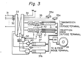
- Figure 3 shows a block diagram of the present common control system which controls a plurality of facsimile terminal apparatuses, and is coupled with other facsimile system through a public telephone line.
- the reference numeral 31 is a public telephone line
- 32 is a reception circuit of the called signal in the telephone line
- 33 is a switching network for exchanging telephone channels
- 34 is an extension telephone line
- 35 is an extension line for a facsimile terminal, which may be either for the use for the facsimile communication only, or common to facsimile communication and telephone communication.
- the reference numeral 35a is a facsimile terminal equipment as shown in Figure 2.
- the reference numeral 36 is a clock signal generator which supplies the clock signal to the facsimile terminal equipment through a line different from the picture signal transmission line.
- the reference numeral 37 is a buffer memory for storing the picture data to and from the terminal equipment 35a.
- the content of that buffer memory 37 is then stored in the magnetic disk memory 39 which has big storage capacity, through the disk control system 38 in a predetermined time, for instance 100 msec.
- That data from the disk 39 is first stored temporarily in that buffer memory 37.
- That buffer memory 37 has the cells in the range from 16 to 128 in the vertical direction, and the cells in the range from 1728 to 2048 in the horizontal direction.
- the number of cells in the vertical direction depends upon the number of cells of the read-head 21 and the printing head 22, and the number of cells in the horizontal direction depends upon the width of the printing paper.
- the content of the buffer memory 37 is transferred to the disk memory 39 for each scanning or travelling of the carriage. When a picture signal is transferred to the disk memory 39, a header information which includes the address that the picture signal is to be transmitted is also written in the disk memory 39.
- the content of the buffer memory 37 is stored in a single truck or in a sector in the truck of the disk memory 39, and then, a data having a picture information and a header information is provided on a disk memory 39.
- the controller 40 controls the address and the input/output of the disk memory 39.
- the header information is first read from the disk memory 39. Then, the address that the picture is to be forwarded is recognized from the header information.
- the available buffer memory 37 is selected. Then, that selected buffer memory 37 is coupled with the called facsimile system through the switching network 33. Then, the disk memory 39 transfers the picture data of a single scanning data to the selected buffer memory 37, which transfers the content of the same to the called facsimile terminal equipment. The transmission of the picture signal from the buffer memory 37 to the called facsimile terminal equipment is performed for each vertical lines (16-128 cells).
- the header and the first picture data are supplied to the other buffer memory 41 from the disk memory 39.
- the control 42 inspects the header, and asks the control 50 of the exchange system 33 to connect the calling facsimile terminal to the called facsimile terminal.
- the switching network 33 forwards the signals for establishing a telephone channel.
- the facsimile communication is accomplished according to the predetermined protocol (communication procedure in a facsimile system), with the called remote facsimile terminal.
- G3 standard the protocol is accomplished using a 300 baud modem, and then, a picture communication is accomplished with the communication speed of 4800 baud/second, or 2400 baud/second.
- the reference numeral 43 is a modem for forwarding and receiving a picture signal and a protocol signal.
- the control 42 effects the coding of the picture signal in the buffer memory 41 to the predetermined coded signal, like a Hoffman code signal.
- the coded signal is stored in the FIFO (first-in- first-out) memory 44.
- the picture signal in the FIFO memory 44 is transmitted to the called facsimile system through the exchange network 33 with the predetermined transmission speed.
- next data for the next scanning is provided to the buffer memory 41 from the disk memory 39 within a predetermined time (for instance 100 msec). That operation is repeated, and when a whole picture information has been transmitted for a whole page, the other protocol for terminating the communication is performed, and the communication for that page is finished.
- the present system can function easily to re-call the other terminal when that terminal is busy, or when the circuit establishment does not succeed, and to forward the same picture signal to a plurality of facsimile terminals at the same time, because the presence of the disk memory 39 which stores the whole picture data.
- the operation for receiving a picture signal from an outside facsimile terminal is as follows. Some particular telephone channels among the telephone channels installed in the switching network 33 are designated for the facsimile communications purpose only.
- the reception circuit 32 detects that facsimile call, and has the switching network 33 connect the reception facsimile call to the reception modem 53, and the reception call control 52 starts the protocol procedure for establishing the facsimile communication.
- the reception modem 53 is composed of the reception circuit of the high speed digital modem, and the both-way modem of the 300 baud modem, or the combination of that both-way 300 baud modem and the reception circuit of a low speed modem.
- the control 38 inspects the header portion at the top of the picture signal thus stored in the disk memory 39, and said control 38 has the switching network 33 connect the facsimile signal on the disk memory 39 to the designated facsimile terminal 35a through the buffer memory 37, the control 40, and the exchange control 50.
- the picture signal is stored in the disk memory 39, and is read-out from that memory 39 to the buffer memory 37, then, that picture signal for each scanning line is transferred to the designated facsimile terminal 35a.
- the picture information for the next scanning line is read-out to the buffer memory 37 from the disk memory 39, and the printing operation is accomplished in the facsimile terminal 35a.
- the reception operation from an outside facsimile terminal is completed.
- the present system may repeat the reception facsimile signal to another outside facsimile terminal, since a picture signal is once stored in a disk memory. Further, the present system may convert the facsimile communication system among G2, G3 and/or the future possible G4 standard.
- a facsimile terminal having the carriage 21 of Figure 2 which has a movable read-head and a movable printing head each processes a plurality of cells in a vertical line at the same time.
- the present invention is of course applicable to another type of facsimile terminal, for instance, a facsimile terminal having a flat-bed type head which has a plurality of cells for the single horizontal line, by modifying the buffer memories 41, 51, and 37: Further, the conversion of the facsimile signal between that of the movable carriage and that of the fixed flat- type head is also possible.
- a plurality set of buffer memories may be installed.
- an additional buffer memory 37 and the control 40 are provided for coupling the disk memory 39 with an internal facsimile terminal.
- Those memory and the control are designated as 37a and 40a in Figure 3.
- the same module as (41-42-43-44) may be provided for transferring the picture data in the disk 39 to an outside facsimile terminal.
- the same module as (51-52-53-54) may be provided to receive a facsimile data from an outside facsimile terminal to the disk memory 39.
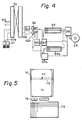
- FIG 4 shows a block diagram of another embodiment of the present facsimile system, and the feature of the present embodiment is the presence of the pattern generator 60.
- the exchange network 33 is the same as that 33 in Figure 3, except that a low speed asynchronous modem 61 (300 baud/sec to 1200 baud/sec) is provided.
- a coded signal (not a scanned picture signal) from an inside terminal 67 or an outside terminal through a telephone line 66 is received by said modem 61. That coded signal represents a character, a letter, and/or a function code, and the coded signal for 100 msec is stored in the buffer memory 62.
- the buffer memory 62 stores one byte or two bytes of coded signal, which is applied to the pattern generator 60.
- the pattern generator 60 generates a character pattern of each coded signal and recognizes a function code, then, the output of the pattern generator 60 is applied to the control 63.
- the control 63 transfers the pattern signal to the buffer memory 64 for each vertical scanning line (having 16-128 cells).
- the operation of the buffer memory 64 is similar to that of the previous buffer memory 51 of Figure 3.
- the buffer memory 64 receives a line return code, or that buffer memory 64 stores the data for the full horizontal line, the content of the buffer memory 64 is transferred to the disk memory 39 within 100 msec.
- the document data in the picture information form is provided on the disk memory 39.
- That picture information on the disk 39 is printed on a facsimile terminal with the same manner as that described in accordane with Figure 3.
- a plurality of modules (61-62-63-64) and 61 a-62a-63a-64a) may be provided.
- the terminal equipment 67 for providing a coded character signal may be an ordinary keyboard type terminal.
- Figure 5 is the modification of the terminal 67, and that terminal of Figure 5 can function as an English word processor and a Japanese word processor.
- the reference numeral 75 shows a flat key board, having a plurality of cells in a matrix arrangement.
- the number of cells is, for instance, 2000 or more.
- the reference numeral 74 shows a plurality of function keys for carriage return, backspace, correction, deletion, insertion, clear copy, and/or printing, and those function keys transfer the corresponding coded signal upon depression.
- the reference numeral 71 is an indicator which shows the arrangement of characters by showing the position of each depressed character on a paper.
- the reference numeral 72 is a line position control
- 73 is a carriage position control
- 77 is a small lamp for indicating the position of a letter.
- the document prepared using that terminal of Figure 5 is printed on a facsimile terminal by one line or one page, upon application of the printing command.
- the lamp 77 designates the position of the character to be corrected, by moving that lamp 77 through the proper depression of the function keys 74. Then, the correction command, and the corrected key depress are accomplished on the key board 75. Then, those coded signals are stored in the buffer memory 64, and in repeating the above operation, the new revised image is obtained on the disk 39.
- the revised image is printed on a facsimile terminal.
- the revised image in the buffer memory 64 is directly printed on a facsimile terminal without transferring the revised image on the disk memory. Further, the revised image may be transmitted to an outside facsimile terminal through a telephone line 66, and in this case, a simple facsimile terminal at a remote location can function to be a word processor.
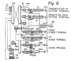
- Figure 6 shows another embodiment of the common control system for the present facsimile system.
- the reference numeral 31 is a telephone channel
- 32 is a reception circuit of the called signal in the telephone line
- 33 is a switching network for exchanging telephone channels
- 34 is an extension telephone line within a building
- 35 is an extension line for a facsimile terminal.
- the reference numeral 36a is a central processing unit for a telephone exchange system, and said unit 36a provides the necessary links for the connection of the channels with the cooperation with the computerized control unit 42, 52, 46, and 56, which are provided for the control of the facsimile communication.
- a facsimile terminal 35a or 75 transmits a picture signal as is follows.
- a facsimile terminal When a facsimile terminal generates a call, that facsimile terminal is connected to the command request circuit 59, which analyzes the address code from a facsimile terminal, and transfers the analyzed information to the picture store control block (47-40b-45) for storing a picture information in the disk memory 39.
- the reference numeral 47 is a memory composed of a pair of 256 bits sub-memories which are utilized alternately for storing a picture data from a facsimile terminal temporarily.
- the data in the memory 47 is converted into the modified Hoffmann code form (G3 standard code recommended by CCITT; MH code) by the coder 40b and the control 46 which are implemented by a micro-computer.
- the converted data is stored in the buffer memory 45. That conversion is accomplished on a real time basis by utilizing a ROM conversion table.
- the buffer memory 45 has a pair of 4k bits sub-memories each of which is used alternately, that is to say, when the first one becomes full, the content of the same is transferred to the disk memory 39 through the disk control 38, and the second one is used for storing the data from the memory 47 during transferring the data of the first one to the disk memory 39.
- a picture signal from a facsimile terminal is stored in the disk memory 39 in the MH code form.
- the information quantity of a picture signal is compressed to 1/5 or 1/10 through the use of that MH code.
- the disk control 38 transmits the address indicating the reception facsimile terminal through the control of the central processing unit 36a to the telephone line, and then, the G3 form transmission circuit (43-44a-41) is coupled with the telephone line through the switching network 33.
- the memory 41 has a pair of 4k bits sub-memories, which are used alternately, for storing the MH coded picture signal from the disk memory 39 temporarily.
- the reference numeral 43 is a modem of 48 baud, or 9600 baud.
- the modem 43 has only to have a transmission side (modulator). That modem 43 may also have a 300 baud modem for the communication of the protocol for establishing the facsimile communication through the control 44a, and the control 42.
- That modem 43 may also have a 300 baud modem for the communication of the protocol for establishing the facsimile communication through the control 44a, and the control 42.
- an outside facsimile terminal can accept an MH code picture signal
- that MH coded picture signal is transmitted directly to the outside terminal.
- the outside terminal can not accept the MH coded picture signal, that MH coded picture signal is converted to the acceptable form (for instance, MR coded picture signal depending upon the outside terminal).
- the block 43-44a-41 may be coupled directly with the telephone line without using the switching network 33.
- the reception operation of the embodiment of Figure 6 is as follows.
- the central control unit 36a couples that reception signal with the available reception route 53-54-51 through the switching network 33.
- the reference numeral 53 has the reception side of a modem, 300 baud modem, and the tone detection function, and functions to handle the G3 standard signal or the G2 standard signal according to the command of the transmission terminal.
- the reception signal is in the MH coded picture signal, that reception signal is directly stored in the buffer memory 51, which has a pair of 4k bits sub-memories, and when the reception signal is in the MR coded picture signal, that received picture signal is converted to an MH coded picture signal, and the converted signal is stored in the memory 51.
- the received picture signal is in the G2 standard form
- that picture signal is also converted to the MH coded picture signal, and is stored in the buffer memory 51.
- the content of the same is transferred to the disk memory 39, and during the transfer to the disk memory, the received picture data is stored in the other sub-memory 51.
- the full page of MH coded picture image is provided on the disk memory 39.
- the route 53-54-51 may be coupled directly with an outside channel without using an exchange network 33.
- the extension facsimile terminal in the building is recognized by the disk control 38, which establishes the necessary route 57-50b-55 for transferring the picture image on the disk memory 39 to the extension facsimile terminal by operating the central processing unit 36a.
- the MH coded signal on the disk is first transferred to one of the sub-memories 55, then, the content of the memory 55 is decoded to an original picture signal by the decoder 50b and the control 56.
- the decoded picture signal is stored in the other buffer memory 57 which has a pair of 256 bits sub-memories.
- the content of the buffer memory 57 is transferred to the inside reception facsimile terminal with the predetermined transmission speed, and the terminal prints when it receives the full data for the scanning line.
- a pair of sub-memories 55 operate alternately, that is to say, when one of them is receiving data from the disk memory 39, the other transfers the content of the same to an external circuit.
- a pair of buffer memories 57 operate alternately.
- the reference numeral 37a is the data bus control coupled with the disk control 38, and that data bus control 37a performs the bus control and the buffer address control.
- the embodiment of Figure 6 can of course handle coded data by installing a module (61a a through 69a), as in the case of Figure 4.
- the reference numeral 61a is a code buffer
- 62a is a control implemented by a micro-computer
- 63a is another control for word processing function
- 64a is a buffer memory for storing a processed data.
- An input data is input from the key board 75a in the coded form.
- the reference numeral 76a shows the coordinates or the arrangement of characters to be input.
- An input character may be either an alphanumerical character, or a Chinese character. Further, the conversion from an alphanumerical character to a Chinese character, is possible by the operation of the control 63a.
- the coded data for a whole page is stored in the buffer memory 64a, and then, transferred to the disk memory 39.
- the key board 75 requests the printing to the disk memory 39, then, one line of data in the memory 39 is read-out into the buffer memory 65a.
- the control 66a and the character generator 68a generate the character pattern for the data in the buffer memory 65a, and the generated character pattern is stored in one of the sub-memories 69a as a main scanning signal for a facsimile terminal. By repeating that operation, the whole printing line is printed on a facsimile paper, and by repeating the printing each lines, the whole page is printed.
- the common control system can double as a PBX telephone exchange system, and can handle a telephone set.
- the present facsimile system is able to be used as a part of a work station of a distributed type computer network, in which a key board terminal and a display terminal coupled with a central computer are located distributely.
Description
- The present invention relates to a facsimile system and in particular to such a system of the centrally controlled type, in which a plurality of simple facsimile transmitters and receivers are controlled centrally by a single central control system. The central control system may be included in a telephone exchange system. The present facsimile system has the advantage that the system can communicate with any facsimile system irrespective of the difference of the technical standard of a communication line and/or a facsimile apparatus.
- A prior facsimile system is shown in Figure 1, in which the reference numeral 1 is a control system of an exchange network, 2 is a modem, 3 is a buffer memory having the capacity of several lines for picture lines, 4 is a coder for coding a picture signal, 5 is a buffer memory for a transmission signal, 6 is a picture sensor and a light, 7 is a pulse motor for feeding a paper for every line, 8 is a buffer memory for a reception signal, 9 is a decoder for decoding a reception signal, 10 is a buffer memory for storing several lines of reception picture signal, 11 is a print head driver and picture distribution circuit, 12 is a print head, 13 is a pulse motor for feeding a paper for every line, and 14 is a control unit and power supply. In some cases, a reception side of a facsimile system has further a picture developing, and fixing system.
- However, a prior facsimile system has the disadvantage that the system has many components and is complicated, since each terminal has its own control system. Further, a prior facsimile system has the disadvantage that a hardware and/or a software for processing the communication procedure defined for a facsimile communication is complicated, and has no compatibility with other facsimile systems. A facsimile communication might be impossible if a modem, or a control procedure of a modem, or a communication procedure of a facsimile system is different from that of the other party. Although the CCITT issued the international standards G1, G2 and G3, the communication among those standards is impossible, and if a facsimile system functions to convert those standards, the price of the facsimile system might become higher.
- While each person in an office has his own telephone set personally, he does not have a facsimile terminal. Therefore, he must bring an original document to be transmitted to a facsimile machine room on foot, and must go to a machine room on foot to receive a facsimile letter. Further, a facsimile letter can not be confidential.
- Reference is also made to an article entitled "Facsimile Response Equipment for Voice Frequency Band" by M. Hiroyama and K. Hattori in Review of the Electrical Communication Laboratories, Vol. 24, No. 5-6 May/June 1976 at pages 341-352. This article describes a centrally- controlled facsimile equipment comprising a plurality of facsimile terminals coupled to an exchange and a control unit for controlling the operation of said facsimile terminals in such a way that signals from one of a plurality of input keyboards, and representative of a picture image, are stored in a magnetic drum memory and may be read out from the drum memory, and transferred via a buffer memory to a designated facsimile terminal.
- The present invention seeks to overcome the disadvantages and limitations of a prior facsimile system by providing a new and improved facsimile system in which a plurality of simple terminal equipments are centrally controlled by a single central controller, and which can handle any facsimile technical standard, including G2 and G3 international standards.
- In accordance with the invention there is provided a centrally controlled facsimile system comprising a plurality of facsimile terminals each having means responsive to electrical signals corresponding to an optically scanned picture for printing the picture on a paper sheet, a central facsimile control system, having at least a switching exchange network for exchanging the connections to said facsimile terminals, a magnetic memory for storing signals corresponding to a picture of a facsimile signal, and a buffer memory for storing a part of facsimile signal when that facsimile signal is stored in or read-out from said magnetic memory, said system being characterised in that said facsimile terminals each have means for converting a picture pattern on an original document to a transmitted electrical facsimile picture signal; in that said switching exchange network is coupled with a plurality of external telephone channels and a plurality of extension telephone channels to provide an exchange function among said extension telephone channels and said external telephone channels; the system being further characterised by a first MODEM provided commonly for said plurality of facsimile terminals and coupled with said switching exchange network for connecting a facsimile terminal with a telephone channel; and wherein said buffer memory is operable to temporarily store a facsimile picture signal which said signal is being stored in or read-out from said magnetic memory; means for compressing a facsimile picture signal and means for reproducing an original facsimile picture signal from a compressed picture signal, whereby a picture signal may be stored in said magnetic memory in compressed form; means for communication protocol control of a facsimile terminal provided common to said plurality of facsimile terminals; and means for controlling the operation of said central facsimile control system whereby a facsimile picture signal generated by one of said plurality of facsimile terminals is first stored in said magnetic memory through said switching exchange network, said facsimile picture signal compressing means and said buffer memory, and the stored facsimile picture signal in said magnetic memory is then transferred to a designated facsimile terminal through said buffer memory, said original facsimile picture reproducing means, and said switching exchange network to produce an image at said designated facsimile terminal.
- In order that the invention may be better understood, several embodiments thereof will now be described by way of example only and with reference to the accompanying drawings in which:-
- Figure 1 is a block diagram of a prior facsimile system;
- Figures 2(a) through 2(d) show the structure of the terminal equipment according to the present facsimile system;
- Figure 3 is a block diagram of the central control system for the present facsimile system;
- Figure 4 shows another block diagram of the central control system for the present facsimile system;
- Figure 5 shows the example of the terminal equipment for the present facsimile system; and
- Figure 6 shows still another block diagram of the central control system for the present facsimile system.
- Figure 2 shows the structure of the terminal equipment according to the present facsimile system. In the figure, the
reference numeral 23 is a carriage having a read-head 21 and aprinting head 22. Thecarriage 23 travels horizontally as shown in Figure 2(b) along theguides 23a, scanning a paper 24 (original paper 24a, andprinting paper 24b). Theoriginal paper 24a travels between theroller 21a a and the read-head 21, and the information on that original paper is read by the read-head 21. Theprinting paper 24b is rolled in the roll-paper 22a, and travels in front of theprinting head 22, which prints on that printing paper. - In the present embodiment, it is supposed that the read-
head 21 and theprinting head 22 are composed of a plurality of picture cells (for instance, the number of cells is in the range from 16 to 128). Therefore, the read-head 21 scans those number of cells in the vertical direction at the same time, and that read-head 21 travels in the horizontal direction A (see Figure 2(c)). When the read-head reaches the right end of thepaper 24a, the paper travels in the vertical direction B by the length equal to the number of cells that the read-head 21 has. Then, the read-head 21 travels and scans thepaper 24a. - Similarly, the
printing head 22 scans theprinting paper 24b, travelling in the horizontal direction A, and when thatprinting head 22 reaches the right end of the paper, the paper travels in the vertical direction B. The number of cells in the vertical direction scanned at the same time by theprinting head 22 is the same as that of the read-head 21. Accordingly, it should be noted that the structure of the present read-head and the printing head is simple, since they are so-called serial type head, and those heads do not have the cells enough to scan the whole horizontal line at the same time. - The read-
head 21 has a plurality of optical- electrical converter-cells, the outputs of which are forwarded to the common control system in a serial signal form. Therefore, no buffer memory is installed in the terminal equipment. - The
printer head 22 may be any type of printing head, including a thermal head which prints on a treated thermal paper by selectively heating the cell, an ink-jet printer, and/or electro-static type printer. Theprinting head 22 stores the data for printing one column from the common control system, and prints them on the printing paper until next column of data are received. - It should be appreciated that the present terminal equipment is very simple in structure, since it has only the read-mechanism, and the printing mechanism, but does not have any control unit.
- Figure 3 shows a block diagram of the present common control system which controls a plurality of facsimile terminal apparatuses, and is coupled with other facsimile system through a public telephone line. In the figure, the
reference numeral 31 is a public telephone line, 32 is a reception circuit of the called signal in the telephone line, 33 is a switching network for exchanging telephone channels, 34 is an extension telephone line, 35 is an extension line for a facsimile terminal, which may be either for the use for the facsimile communication only, or common to facsimile communication and telephone communication. Thereference numeral 35a is a facsimile terminal equipment as shown in Figure 2. Thereference numeral 36 is a clock signal generator which supplies the clock signal to the facsimile terminal equipment through a line different from the picture signal transmission line. Thereference numeral 37 is a buffer memory for storing the picture data to and from theterminal equipment 35a. The content of thatbuffer memory 37 is then stored in themagnetic disk memory 39 which has big storage capacity, through thedisk control system 38 in a predetermined time, for instance 100 msec. When the content of themagnetic disk 39 is read, that data from thedisk 39 is first stored temporarily in thatbuffer memory 37. Thatbuffer memory 37 has the cells in the range from 16 to 128 in the vertical direction, and the cells in the range from 1728 to 2048 in the horizontal direction. The number of cells in the vertical direction depends upon the number of cells of the read-head 21 and theprinting head 22, and the number of cells in the horizontal direction depends upon the width of the printing paper. The content of thebuffer memory 37 is transferred to thedisk memory 39 for each scanning or travelling of the carriage. When a picture signal is transferred to thedisk memory 39, a header information which includes the address that the picture signal is to be transmitted is also written in thedisk memory 39. The content of thebuffer memory 37 is stored in a single truck or in a sector in the truck of thedisk memory 39, and then, a data having a picture information and a header information is provided on adisk memory 39. Thecontroller 40 controls the address and the input/output of thedisk memory 39. - When the content of the
disk memory 39 is to be transferred to another facsimile equipment, the header information is first read from thedisk memory 39. Then, the address that the picture is to be forwarded is recognized from the header information. When the address that the picture is to be forwarded shows the facsimile system within the same building as that in which the common control system is installed, theavailable buffer memory 37 is selected. Then, that selectedbuffer memory 37 is coupled with the called facsimile system through theswitching network 33. Then, thedisk memory 39 transfers the picture data of a single scanning data to the selectedbuffer memory 37, which transfers the content of the same to the called facsimile terminal equipment. The transmission of the picture signal from thebuffer memory 37 to the called facsimile terminal equipment is performed for each vertical lines (16-128 cells). When all the data in thebuffer memory 37 is forwarded to the called terminal,-the new data of the new vertical scanning line is supplied to thebuffer memory 37 from thedisk memory 39. By repeating the above process, a whole page of picture information is forwarded from thedisk memory 39 to the called facsimile terminal equipment. Since a picture information is stored in thedisk memory 39, that picture information is transferred to the called terminal when that called terminal is not busy. Further, the same picture can be distributed to a plurality of facsimile terminals. - When the designated address shows the outside facsimile terminal which is installed outside the building, the header and the first picture data are supplied to the
other buffer memory 41 from thedisk memory 39. Thecontrol 42 inspects the header, and asks thecontrol 50 of theexchange system 33 to connect the calling facsimile terminal to the called facsimile terminal. In this case, the switchingnetwork 33 forwards the signals for establishing a telephone channel. After the telephone channel is established, the facsimile communication is accomplished according to the predetermined protocol (communication procedure in a facsimile system), with the called remote facsimile terminal. When G3 standard is utilized, the protocol is accomplished using a 300 baud modem, and then, a picture communication is accomplished with the communication speed of 4800 baud/second, or 2400 baud/second. When G2 international standard is utilized, the protocol is accomplished using a tone signal, and a picture signal is transmitted using an AM-PM-VSM modem. Thereference numeral 43 is a modem for forwarding and receiving a picture signal and a protocol signal. When a picture signal is transmitted, thecontrol 42 effects the coding of the picture signal in thebuffer memory 41 to the predetermined coded signal, like a Hoffman code signal. The coded signal is stored in the FIFO (first-in- first-out)memory 44. The picture signal in theFIFO memory 44 is transmitted to the called facsimile system through theexchange network 33 with the predetermined transmission speed. When a data for a single scanning has been forwarded, or all the data in thebuffer memory 41 is forwarded, next data for the next scanning is provided to thebuffer memory 41 from thedisk memory 39 within a predetermined time (for instance 100 msec). That operation is repeated, and when a whole picture information has been transmitted for a whole page, the other protocol for terminating the communication is performed, and the communication for that page is finished. - It should be appreciated that the present system can function easily to re-call the other terminal when that terminal is busy, or when the circuit establishment does not succeed, and to forward the same picture signal to a plurality of facsimile terminals at the same time, because the presence of the
disk memory 39 which stores the whole picture data. - The operation for receiving a picture signal from an outside facsimile terminal is as follows. Some particular telephone channels among the telephone channels installed in the
switching network 33 are designated for the facsimile communications purpose only. When a facsimile call is received in those facsimile channels, thereception circuit 32 detects that facsimile call, and has theswitching network 33 connect the reception facsimile call to thereception modem 53, and thereception call control 52 starts the protocol procedure for establishing the facsimile communication. Thereception modem 53 is composed of the reception circuit of the high speed digital modem, and the both-way modem of the 300 baud modem, or the combination of that both-way 300 baud modem and the reception circuit of a low speed modem. When a picture signal is received, that picture signal is stored in the FIFO (first-in- first-out)memory 54. Then, thecontrol 52 reads that content of theFIFO memory 54 one bit after another to decode the received Hoffmann code, and the decoded picture signal is stored in thebuffer memory 51. When thebuffer memory 51 stores the picture signal for one scanning line, that picture signal is transferred to thedisk memory 39 within 100 msec. By repeating the above operation, a whole picture signal for a page is obtained on adisk memory 39. Then, the protocol procedure is accomplished for finishing the facsimile communication. Next, thecontrol 38 inspects the header portion at the top of the picture signal thus stored in thedisk memory 39, and saidcontrol 38 has theswitching network 33 connect the facsimile signal on thedisk memory 39 to the designatedfacsimile terminal 35a through thebuffer memory 37, thecontrol 40, and theexchange control 50. The picture signal is stored in thedisk memory 39, and is read-out from thatmemory 39 to thebuffer memory 37, then, that picture signal for each scanning line is transferred to the designatedfacsimile terminal 35a. When the reception operation or the printing operation for one scanning line is finished in thefacsimile terminal 35a, the picture information for the next scanning line is read-out to thebuffer memory 37 from thedisk memory 39, and the printing operation is accomplished in thefacsimile terminal 35a. Thus, the reception operation from an outside facsimile terminal is completed. - It should be noted that the present system may repeat the reception facsimile signal to another outside facsimile terminal, since a picture signal is once stored in a disk memory. Further, the present system may convert the facsimile communication system among G2, G3 and/or the future possible G4 standard.
- The above explanation is described for a facsimile terminal having the
carriage 21 of Figure 2, which has a movable read-head and a movable printing head each processes a plurality of cells in a vertical line at the same time. However, it should be noted that the present invention is of course applicable to another type of facsimile terminal, for instance, a facsimile terminal having a flat-bed type head which has a plurality of cells for the single horizontal line, by modifying thebuffer memories - In order to facilitate that the
disk 39 may process a plurality of facsimile communications at the same time, a plurality set of buffer memories may be installed. Thus, anadditional buffer memory 37 and thecontrol 40 are provided for coupling thedisk memory 39 with an internal facsimile terminal. Those memory and the control are designated as 37a and 40a in Figure 3. Similarly, the same module as (41-42-43-44) may be provided for transferring the picture data in thedisk 39 to an outside facsimile terminal. Further, the same module as (51-52-53-54) may be provided to receive a facsimile data from an outside facsimile terminal to thedisk memory 39. - Figure 4 shows a block diagram of another embodiment of the present facsimile system, and the feature of the present embodiment is the presence of the pattern generator 60. In the figure, the
exchange network 33 is the same as that 33 in Figure 3, except that a low speed asynchronous modem 61 (300 baud/sec to 1200 baud/sec) is provided. In this embodiment, a coded signal (not a scanned picture signal) from aninside terminal 67 or an outside terminal through atelephone line 66 is received by saidmodem 61. That coded signal represents a character, a letter, and/or a function code, and the coded signal for 100 msec is stored in thebuffer memory 62. Thus, thebuffer memory 62 stores one byte or two bytes of coded signal, which is applied to the pattern generator 60. The pattern generator 60 generates a character pattern of each coded signal and recognizes a function code, then, the output of the pattern generator 60 is applied to the control 63. The control 63 transfers the pattern signal to thebuffer memory 64 for each vertical scanning line (having 16-128 cells). The operation of thebuffer memory 64 is similar to that of theprevious buffer memory 51 of Figure 3. When thebuffer memory 64 receives a line return code, or thatbuffer memory 64 stores the data for the full horizontal line, the content of thebuffer memory 64 is transferred to thedisk memory 39 within 100 msec. Thus, the document data in the picture information form is provided on thedisk memory 39. That picture information on thedisk 39 is printed on a facsimile terminal with the same manner as that described in accordane with Figure 3. In order to facilitate the simultaneous operation, a plurality of modules (61-62-63-64) and 61 a-62a-63a-64a) may be provided. - The
terminal equipment 67 for providing a coded character signal may be an ordinary keyboard type terminal. Figure 5 is the modification of the terminal 67, and that terminal of Figure 5 can function as an English word processor and a Japanese word processor. - In Figure 5, the
reference numeral 75 shows a flat key board, having a plurality of cells in a matrix arrangement. When that key board is used as a Japanese terminal, the number of cells is, for instance, 2000 or more. When one of the cells is pushed with a pen, that cell generates a coded signal by detecting the pressure by the pen. The reference numeral 74 shows a plurality of function keys for carriage return, backspace, correction, deletion, insertion, clear copy, and/or printing, and those function keys transfer the corresponding coded signal upon depression. Thereference numeral 71 is an indicator which shows the arrangement of characters by showing the position of each depressed character on a paper. Thereference numeral 72 is a line position control, 73 is a carriage position control, and 77 is a small lamp for indicating the position of a letter. The document prepared using that terminal of Figure 5 is printed on a facsimile terminal by one line or one page, upon application of the printing command. - When the document thus prepared is to be corrected or revised, a printed copy is put on the
indicator 71, and then, thelamp 77 designates the position of the character to be corrected, by moving thatlamp 77 through the proper depression of the function keys 74. Then, the correction command, and the corrected key depress are accomplished on thekey board 75. Then, those coded signals are stored in thebuffer memory 64, and in repeating the above operation, the new revised image is obtained on thedisk 39. The revised image is printed on a facsimile terminal. Alternatively, the revised image in thebuffer memory 64 is directly printed on a facsimile terminal without transferring the revised image on the disk memory. Further, the revised image may be transmitted to an outside facsimile terminal through atelephone line 66, and in this case, a simple facsimile terminal at a remote location can function to be a word processor. - It should be appreciated that the structure of the key board of Figure 5 is very simple, and thus, the combination of the terminal of Figure 2 and the terminal of Figure 5 can provide the simplified facsimile system.
- Figure 6 shows another embodiment of the common control system for the present facsimile system. In the figure, the
reference numeral 31 is a telephone channel, 32 is a reception circuit of the called signal in the telephone line, 33 is a switching network for exchanging telephone channels, 34 is an extension telephone line within a building, 35 is an extension line for a facsimile terminal. The reference numeral 36a is a central processing unit for a telephone exchange system, and said unit 36a provides the necessary links for the connection of the channels with the cooperation with thecomputerized control unit - The transmission operation in which a
facsimile terminal command request circuit 59, which analyzes the address code from a facsimile terminal, and transfers the analyzed information to the picture store control block (47-40b-45) for storing a picture information in thedisk memory 39. Thereference numeral 47 is a memory composed of a pair of 256 bits sub-memories which are utilized alternately for storing a picture data from a facsimile terminal temporarily. The data in thememory 47 is converted into the modified Hoffmann code form (G3 standard code recommended by CCITT; MH code) by the coder 40b and the control 46 which are implemented by a micro-computer. The converted data is stored in thebuffer memory 45. That conversion is accomplished on a real time basis by utilizing a ROM conversion table. Thebuffer memory 45 has a pair of 4k bits sub-memories each of which is used alternately, that is to say, when the first one becomes full, the content of the same is transferred to thedisk memory 39 through thedisk control 38, and the second one is used for storing the data from thememory 47 during transferring the data of the first one to thedisk memory 39. By repeating the above operation, a picture signal from a facsimile terminal is stored in thedisk memory 39 in the MH code form. The information quantity of a picture signal is compressed to 1/5 or 1/10 through the use of that MH code. Next, thedisk control 38 transmits the address indicating the reception facsimile terminal through the control of the central processing unit 36a to the telephone line, and then, the G3 form transmission circuit (43-44a-41) is coupled with the telephone line through theswitching network 33. Thememory 41 has a pair of 4k bits sub-memories, which are used alternately, for storing the MH coded picture signal from thedisk memory 39 temporarily. Thereference numeral 43 is a modem of 48 baud, or 9600 baud. In this embodiment, themodem 43 has only to have a transmission side (modulator). Thatmodem 43 may also have a 300 baud modem for the communication of the protocol for establishing the facsimile communication through the control 44a, and thecontrol 42. When an outside facsimile terminal can accept an MH code picture signal, that MH coded picture signal is transmitted directly to the outside terminal. On the other hand, when the outside terminal can not accept the MH coded picture signal, that MH coded picture signal is converted to the acceptable form (for instance, MR coded picture signal depending upon the outside terminal). The block 43-44a-41 may be coupled directly with the telephone line without using theswitching network 33. - The reception operation of the embodiment of Figure 6 is as follows. When the reception signal in the
telephone line 31 is detected by thereception circuit 32, the central control unit 36a couples that reception signal with the available reception route 53-54-51 through theswitching network 33. Thereference numeral 53 has the reception side of a modem, 300 baud modem, and the tone detection function, and functions to handle the G3 standard signal or the G2 standard signal according to the command of the transmission terminal. When the reception signal is in the MH coded picture signal, that reception signal is directly stored in thebuffer memory 51, which has a pair of 4k bits sub-memories, and when the reception signal is in the MR coded picture signal, that received picture signal is converted to an MH coded picture signal, and the converted signal is stored in thememory 51. When the received picture signal is in the G2 standard form, that picture signal is also converted to the MH coded picture signal, and is stored in thebuffer memory 51. When one of the sub-memories 51 becomes full, the content of the same is transferred to thedisk memory 39, and during the transfer to the disk memory, the received picture data is stored in theother sub-memory 51. By repeating the above operation, the full page of MH coded picture image is provided on thedisk memory 39. The route 53-54-51 may be coupled directly with an outside channel without using anexchange network 33. - Next, the extension facsimile terminal in the building is recognized by the
disk control 38, which establishes the necessary route 57-50b-55 for transferring the picture image on thedisk memory 39 to the extension facsimile terminal by operating the central processing unit 36a. The MH coded signal on the disk is first transferred to one of the sub-memories 55, then, the content of thememory 55 is decoded to an original picture signal by the decoder 50b and thecontrol 56. The decoded picture signal is stored in the other buffer memory 57 which has a pair of 256 bits sub-memories. The content of the buffer memory 57 is transferred to the inside reception facsimile terminal with the predetermined transmission speed, and the terminal prints when it receives the full data for the scanning line. - A pair of
sub-memories 55 operate alternately, that is to say, when one of them is receiving data from thedisk memory 39, the other transfers the content of the same to an external circuit. Similarly, a pair of buffer memories 57 operate alternately. - The
reference numeral 37a is the data bus control coupled with thedisk control 38, and thatdata bus control 37a performs the bus control and the buffer address control. - The embodiment of Figure 6 can of course handle coded data by installing a module (61a a through 69a), as in the case of Figure 4. In the module, the reference numeral 61a is a code buffer, 62a is a control implemented by a micro-computer, 63a is another control for word processing function, and 64a is a buffer memory for storing a processed data. An input data is input from the key board 75a in the coded form. The reference numeral 76a shows the coordinates or the arrangement of characters to be input. An input character may be either an alphanumerical character, or a Chinese character. Further, the conversion from an alphanumerical character to a Chinese character, is possible by the operation of the
control 63a. The coded data for a whole page is stored in thebuffer memory 64a, and then, transferred to thedisk memory 39. - When the content of the
disk memory 39 is to be printed on a facsimile terminal, thekey board 75 requests the printing to thedisk memory 39, then, one line of data in thememory 39 is read-out into thebuffer memory 65a. The control 66a and the character generator 68a generate the character pattern for the data in thebuffer memory 65a, and the generated character pattern is stored in one of the sub-memories 69a as a main scanning signal for a facsimile terminal. By repeating that operation, the whole printing line is printed on a facsimile paper, and by repeating the printing each lines, the whole page is printed. - Finally, some effects particular to the present invention are listed below.
- a) A plurality of facsimile terminals with simple structure are installed. Therefore, a person can use a facsimile terminal at any location any time, as in the case of a telephone set.
- b) A coded data generated by a keyboard can be received by a facsimile terminal.
- c) Since many facsimile terminals are installed in a building, the manual distribution of the received facsimile letter is unnecessary.
- d) Since the received facsimile letter is stored in a disk memory, that letter can be confidential. When the letter is to be printed, one can print the facsimile letter personally.
- e) A plurality of the same data can be distributed to a plurality of facsimile terminals at the same time, by forwarding the letter from the disk memory to the terminals.
- f) The number of facsimile terminals can be increased easily, since the structure of the same is simple.
- g) When a new facsimile technical standard is issued, the present invention can easuly handle that new standard, by attaching a new module for handling the new standard to the circit of Figure 3, Figure 4 or Figure 5.
- h) When a facsimile data is compressed, for instance, by using a Hoffman code, the capacity of the disk memory is reduced.
- i) The common control system can double as a PBX telephone exchange system, and can handle a telephone set.
- j) The present facsimile system is able to be used as a part of a work station of a distributed type computer network, in which a key board terminal and a display terminal coupled with a central computer are located distributely.
- From the foregoing it will now be apparent that a new and improved facsimile system has been found. It should be understood of course that the embodiments disclosed are merely illustrative and are not intended to limit the scope of the invention. Reference should be made to the appended claims, therefore, rather than the specification as indicating the scope of the invention.
Claims (2)
Applications Claiming Priority (4)
| Application Number | Priority Date | Filing Date | Title |
|---|---|---|---|
| JP169694/80 | 1980-12-03 | ||
| JP55169694A JPS5793771A (en) | 1980-12-03 | 1980-12-03 | Centralized control type facsimile |
| JP14402/81 | 1981-02-04 | ||
| JP56014402A JPS57129567A (en) | 1981-02-04 | 1981-02-04 | Centralized control type facsimile device |
Publications (3)
| Publication Number | Publication Date |
|---|---|
| EP0053469A2 EP0053469A2 (en) | 1982-06-09 |
| EP0053469A3 EP0053469A3 (en) | 1986-03-05 |
| EP0053469B1 true EP0053469B1 (en) | 1988-08-10 |
Family
ID=26350343
Family Applications (1)
| Application Number | Title | Priority Date | Filing Date |
|---|---|---|---|
| EP81305545A Expired EP0053469B1 (en) | 1980-12-03 | 1981-11-24 | Centrally controlled facsimile system |
Country Status (3)
| Country | Link |
|---|---|
| US (1) | US4491873A (en) |
| EP (1) | EP0053469B1 (en) |
| DE (1) | DE3176843D1 (en) |
Families Citing this family (44)
| Publication number | Priority date | Publication date | Assignee | Title |
|---|---|---|---|---|
| US4646160A (en) * | 1982-08-30 | 1987-02-24 | Fujitsu Limited | Facsimile apparatus |
| GB2132050B (en) * | 1982-10-18 | 1986-10-22 | Canon Kk | Facsimile system |
| US4791492A (en) * | 1983-04-12 | 1988-12-13 | Canon Kabushiki Kaisha | Image processing system |
| JPS6021671A (en) * | 1983-07-18 | 1985-02-04 | Canon Inc | Image reading device |
| JPS6084672A (en) * | 1983-10-17 | 1985-05-14 | Canon Inc | Image processing system |
| GB8408320D0 (en) * | 1984-03-30 | 1984-05-10 | Int Computers Ltd | Facsimile system |
| JPH07105879B2 (en) * | 1984-07-04 | 1995-11-13 | 日本電信電話株式会社 | Image processing device |
| US4677492A (en) * | 1984-07-06 | 1987-06-30 | Siemens Aktiengesellschaft | Method for the intermediate storage of facsimile data of groups 2 and 3 |
| US4727435A (en) | 1984-09-21 | 1988-02-23 | Canon Kabushiki Kaisha | Image information processing system |
| US4706126A (en) * | 1984-11-02 | 1987-11-10 | Ricoh Company. Ltd. | Facsimile apparatus |
| US4814890A (en) * | 1984-11-19 | 1989-03-21 | Canon Kabushiki Kaisha | Image communicating system |
| GB2169174B (en) * | 1984-11-28 | 1989-06-01 | Canon Kk | Data communication apparatus |
| US4772955A (en) * | 1985-01-31 | 1988-09-20 | Canon Kabushiki Kaisha | Data communication apparatus |
| US4746986A (en) * | 1985-03-04 | 1988-05-24 | Ricoh Company, Ltd. | Manifold analog/digital facsimile apparatus |
| US4827349A (en) * | 1985-04-30 | 1989-05-02 | Canon Kabushiki Kaisha | Communication terminal device |
| JPS62142457A (en) * | 1985-12-17 | 1987-06-25 | Canon Inc | Picture transmission and reception equipment |
| US5040031A (en) * | 1986-05-10 | 1991-08-13 | Canon Kabushiki Kaisha | Image processing apparatus which can control output to multiple devices to accommodate differing operating timing of those devices |
| WO1987007107A1 (en) * | 1986-05-16 | 1987-11-19 | Canon Kabushiki Kaisha | Data communication equipment |
| US5270805A (en) * | 1986-05-16 | 1993-12-14 | Canon Kabushiki Kaisha | Data communication apparatus for converting data in accordance with a discriminated function of a destination station |
| JPS63146558A (en) * | 1986-12-09 | 1988-06-18 | Hitachi Ltd | Facsimile communication system |
| US4764870A (en) * | 1987-04-09 | 1988-08-16 | R.A.P.I.D., Inc. | System and method for remote presentation of diagnostic image information |
| US5005126A (en) * | 1987-04-09 | 1991-04-02 | Prevail, Inc. | System and method for remote presentation of diagnostic image information |
| US4897799A (en) * | 1987-09-15 | 1990-01-30 | Bell Communications Research, Inc. | Format independent visual communications |
| US4935955A (en) * | 1988-06-03 | 1990-06-19 | Neudorfer Julius N | Facsimile PBX with storage and security |
| JPH0279575A (en) * | 1988-09-14 | 1990-03-20 | Fujitsu Ltd | Picture display terminal with transmitter function |
| US7365884B2 (en) * | 1988-09-22 | 2008-04-29 | Catch Curve, Inc. | Facsimile telecommunications system and method |
| US6785021B1 (en) * | 1988-09-22 | 2004-08-31 | Audiofax, Ip, Llc | Facsimile telecommunications system and method |
| US5459584A (en) | 1988-09-22 | 1995-10-17 | Audiofax, Inc. | Facsimile telecommunications system and method |
| US4994926C1 (en) * | 1988-09-22 | 2001-07-03 | Audiofax Ip L L C | Facsimile telecommunications system and method |
| US5339174A (en) * | 1989-05-02 | 1994-08-16 | Harris Scott C | Facsimile machine time shifting and converting apparatus |
| US5003583A (en) * | 1989-05-15 | 1991-03-26 | Iggulden Jerry R | Facsimile printer broadcast exchange (PBX) |
| US5018191A (en) * | 1989-10-23 | 1991-05-21 | At&T Bell Laboratories | Special service call routing |
| AU6167090A (en) * | 1989-07-21 | 1991-02-22 | Xpedite Systems, Inc. | Electronic mail broadcasting system |
| US5157519A (en) * | 1989-08-24 | 1992-10-20 | Fujitsu America, Inc. | Serial computer peripheral for facsimile image and ascii text communication |
| US7525691B2 (en) * | 1991-02-12 | 2009-04-28 | Catch Curve, Inc. | Facsimile telecommunications system and method |
| US5200993A (en) * | 1991-05-10 | 1993-04-06 | Bell Atlantic Network Services, Inc. | Public telephone network including a distributed imaging system |
| JP3289283B2 (en) * | 1991-05-13 | 2002-06-04 | キヤノン株式会社 | Facsimile apparatus and control method thereof |
| US6323961B1 (en) | 1992-11-06 | 2001-11-27 | Michael I. Rackman | Facsimile machine for printing documents with selectively aligned edges |
| US5311607A (en) * | 1993-08-25 | 1994-05-10 | Crosby Peter A | Facsimile machine for printing documents all with corresponding edges aligned but without requiring scanning |
| US5881142A (en) * | 1995-07-18 | 1999-03-09 | Jetstream Communications, Inc. | Integrated communications control device for a small office configured for coupling within a scalable network |
| KR100294214B1 (en) * | 1998-11-18 | 2001-10-26 | 윤종용 | Universal fax machine supporting multi-national communication environment and its control method |
| US20050197860A1 (en) * | 2004-02-23 | 2005-09-08 | Rademr, Inc. | Data management system |
| US7953612B1 (en) | 2006-07-17 | 2011-05-31 | Ecomglobalmedical Research & Development, Inc | System and method for providing a searchable database of surgical information |
| CN111565257B (en) * | 2020-04-14 | 2022-11-08 | 深圳震有科技股份有限公司 | Transcoding method, device, system and medium of fax terminal |
Family Cites Families (4)
| Publication number | Priority date | Publication date | Assignee | Title |
|---|---|---|---|---|
| US3751582A (en) * | 1971-12-08 | 1973-08-07 | Addressograph Multigraph | Stored program facsimile control system |
| US3798610A (en) * | 1972-12-20 | 1974-03-19 | Ibm | Multiplexed intelligence communications |
| US4110794A (en) * | 1977-02-03 | 1978-08-29 | Static Systems Corporation | Electronic typewriter using a solid state display to print |
| JPS55138967A (en) * | 1979-04-17 | 1980-10-30 | Fuji Xerox Co Ltd | Copying machine |
-
1981
- 1981-11-24 EP EP81305545A patent/EP0053469B1/en not_active Expired
- 1981-11-24 DE DE8181305545T patent/DE3176843D1/en not_active Expired
- 1981-11-24 US US06/324,597 patent/US4491873A/en not_active Expired - Lifetime
Also Published As
| Publication number | Publication date |
|---|---|
| EP0053469A3 (en) | 1986-03-05 |
| US4491873A (en) | 1985-01-01 |
| EP0053469A2 (en) | 1982-06-09 |
| DE3176843D1 (en) | 1988-09-15 |
Similar Documents
| Publication | Publication Date | Title |
|---|---|---|
| EP0053469B1 (en) | Centrally controlled facsimile system | |
| JP2733220B2 (en) | Composite image processing device | |
| US4759053A (en) | Facsimile/character communication system | |
| CA1178367A (en) | Office communications system | |
| EP0488274B1 (en) | Method and apparatus for decoding and printing coded images | |
| JPS5814654A (en) | Facsimile communication system | |
| GB2184913A (en) | Facsimile apparatus | |
| US4547628A (en) | Data transmission system | |
| JPH0318381B2 (en) | ||
| JPS6230547B2 (en) | ||
| JPS59165558A (en) | Facsimile response system | |
| JPH0244851A (en) | Facsimile equipment | |
| JP2501775B2 (en) | Fax machine | |
| KR100338068B1 (en) | Method for control transmitting and receiving state in the facsimile | |
| JPH0548781A (en) | Facsimile equipment | |
| JP2523242B2 (en) | Telephone code printing device | |
| JPH07112221B2 (en) | Equipment | |
| KR950002309B1 (en) | Data changing device for fax | |
| Kamae | Visual terminals and user interfaces | |
| JPS6351589B2 (en) | ||
| JP2558641B2 (en) | Method for accommodating a facsimile device in an electronic exchange | |
| JPH01294071A (en) | Printer with facsimile function | |
| JPH023351B2 (en) | ||
| JPS58146171A (en) | Character recognizing device | |
| JPS58195355A (en) | Character recognizing device |
Legal Events
| Date | Code | Title | Description |
|---|---|---|---|
| PUAI | Public reference made under article 153(3) epc to a published international application that has entered the european phase |
Free format text: ORIGINAL CODE: 0009012 |
|
| AK | Designated contracting states |
Designated state(s): DE FR GB IT |
|
| PUAL | Search report despatched |
Free format text: ORIGINAL CODE: 0009013 |
|
| AK | Designated contracting states |
Kind code of ref document: A3 Designated state(s): DE FR GB IT |
|
| 17P | Request for examination filed |
Effective date: 19860424 |
|
| 17Q | First examination report despatched |
Effective date: 19870508 |
|
| GRAA | (expected) grant |
Free format text: ORIGINAL CODE: 0009210 |
|
| AK | Designated contracting states |
Kind code of ref document: B1 Designated state(s): DE FR GB IT |
|
| ITF | It: translation for a ep patent filed |
Owner name: JACOBACCI & PERANI S.P.A. |
|
| REF | Corresponds to: |
Ref document number: 3176843 Country of ref document: DE Date of ref document: 19880915 |
|
| ET | Fr: translation filed | ||
| PLBE | No opposition filed within time limit |
Free format text: ORIGINAL CODE: 0009261 |
|
| STAA | Information on the status of an ep patent application or granted ep patent |
Free format text: STATUS: NO OPPOSITION FILED WITHIN TIME LIMIT |
|
| 26N | No opposition filed | ||
| ITTA | It: last paid annual fee | ||
| PGFP | Annual fee paid to national office [announced via postgrant information from national office to epo] |
Ref country code: FR Payment date: 19961111 Year of fee payment: 16 |
|
| PGFP | Annual fee paid to national office [announced via postgrant information from national office to epo] |
Ref country code: GB Payment date: 19961115 Year of fee payment: 16 |
|
| PGFP | Annual fee paid to national office [announced via postgrant information from national office to epo] |
Ref country code: DE Payment date: 19961202 Year of fee payment: 16 |
|
| PG25 | Lapsed in a contracting state [announced via postgrant information from national office to epo] |
Ref country code: GB Free format text: LAPSE BECAUSE OF NON-PAYMENT OF DUE FEES Effective date: 19971124 |
|
| PG25 | Lapsed in a contracting state [announced via postgrant information from national office to epo] |
Ref country code: FR Free format text: THE PATENT HAS BEEN ANNULLED BY A DECISION OF A NATIONAL AUTHORITY Effective date: 19971130 |
|
| GBPC | Gb: european patent ceased through non-payment of renewal fee |
Effective date: 19971124 |
|
| PG25 | Lapsed in a contracting state [announced via postgrant information from national office to epo] |
Ref country code: DE Free format text: LAPSE BECAUSE OF NON-PAYMENT OF DUE FEES Effective date: 19980801 |
|
| REG | Reference to a national code |
Ref country code: FR Ref legal event code: ST |