EP0052984B1 - Improved trolley or carriage assembly - Google Patents
Improved trolley or carriage assembly Download PDFInfo
- Publication number
- EP0052984B1 EP0052984B1 EP81305380A EP81305380A EP0052984B1 EP 0052984 B1 EP0052984 B1 EP 0052984B1 EP 81305380 A EP81305380 A EP 81305380A EP 81305380 A EP81305380 A EP 81305380A EP 0052984 B1 EP0052984 B1 EP 0052984B1
- Authority
- EP
- European Patent Office
- Prior art keywords
- trolley
- shaft
- inner race
- assembly
- shield
- Prior art date
- Legal status (The legal status is an assumption and is not a legal conclusion. Google has not performed a legal analysis and makes no representation as to the accuracy of the status listed.)
- Expired
Links
- 238000005096 rolling process Methods 0.000 claims description 12
- 125000006850 spacer group Chemical group 0.000 claims description 10
- 239000002184 metal Substances 0.000 claims description 8
- 239000000314 lubricant Substances 0.000 claims description 6
- 238000005461 lubrication Methods 0.000 claims description 4
- 238000011109 contamination Methods 0.000 claims description 2
- 230000000712 assembly Effects 0.000 description 14
- 238000000429 assembly Methods 0.000 description 14
- 238000000034 method Methods 0.000 description 7
- 230000000295 complement effect Effects 0.000 description 5
- 230000006835 compression Effects 0.000 description 4
- 238000007906 compression Methods 0.000 description 4
- 238000009826 distribution Methods 0.000 description 4
- 230000000717 retained effect Effects 0.000 description 4
- 239000004519 grease Substances 0.000 description 3
- 238000003754 machining Methods 0.000 description 3
- 230000002028 premature Effects 0.000 description 3
- 229910000831 Steel Inorganic materials 0.000 description 2
- 238000005266 casting Methods 0.000 description 2
- 238000003780 insertion Methods 0.000 description 2
- 230000037431 insertion Effects 0.000 description 2
- 239000007788 liquid Substances 0.000 description 2
- 239000010959 steel Substances 0.000 description 2
- 230000001154 acute effect Effects 0.000 description 1
- 239000000969 carrier Substances 0.000 description 1
- 239000000356 contaminant Substances 0.000 description 1
- 230000003247 decreasing effect Effects 0.000 description 1
- 230000009977 dual effect Effects 0.000 description 1
- 230000008030 elimination Effects 0.000 description 1
- 238000003379 elimination reaction Methods 0.000 description 1
- 238000005242 forging Methods 0.000 description 1
- 238000012423 maintenance Methods 0.000 description 1
- 230000014759 maintenance of location Effects 0.000 description 1
- 239000000463 material Substances 0.000 description 1
- 230000013011 mating Effects 0.000 description 1
- 230000002093 peripheral effect Effects 0.000 description 1
- 230000000750 progressive effect Effects 0.000 description 1
- 230000001737 promoting effect Effects 0.000 description 1
Images

Classifications
-
- B—PERFORMING OPERATIONS; TRANSPORTING
- B65—CONVEYING; PACKING; STORING; HANDLING THIN OR FILAMENTARY MATERIAL
- B65G—TRANSPORT OR STORAGE DEVICES, e.g. CONVEYORS FOR LOADING OR TIPPING, SHOP CONVEYOR SYSTEMS OR PNEUMATIC TUBE CONVEYORS
- B65G9/00—Apparatus for assisting manual handling having suspended load-carriers movable by hand or gravity
- B65G9/002—Load-carriers, rollers therefor
-
- B—PERFORMING OPERATIONS; TRANSPORTING
- B60—VEHICLES IN GENERAL
- B60B—VEHICLE WHEELS; CASTORS; AXLES FOR WHEELS OR CASTORS; INCREASING WHEEL ADHESION
- B60B33/00—Castors in general; Anti-clogging castors
- B60B33/0028—Construction of wheels; methods of assembling on axle
-
- B—PERFORMING OPERATIONS; TRANSPORTING
- B65—CONVEYING; PACKING; STORING; HANDLING THIN OR FILAMENTARY MATERIAL
- B65G—TRANSPORT OR STORAGE DEVICES, e.g. CONVEYORS FOR LOADING OR TIPPING, SHOP CONVEYOR SYSTEMS OR PNEUMATIC TUBE CONVEYORS
- B65G17/00—Conveyors having an endless traction element, e.g. a chain, transmitting movement to a continuous or substantially-continuous load-carrying surface or to a series of individual load-carriers; Endless-chain conveyors in which the chains form the load-carrying surface
- B65G17/20—Conveyors having an endless traction element, e.g. a chain, transmitting movement to a continuous or substantially-continuous load-carrying surface or to a series of individual load-carriers; Endless-chain conveyors in which the chains form the load-carrying surface comprising load-carriers suspended from overhead traction chains
-
- F—MECHANICAL ENGINEERING; LIGHTING; HEATING; WEAPONS; BLASTING
- F16—ENGINEERING ELEMENTS AND UNITS; GENERAL MEASURES FOR PRODUCING AND MAINTAINING EFFECTIVE FUNCTIONING OF MACHINES OR INSTALLATIONS; THERMAL INSULATION IN GENERAL
- F16C—SHAFTS; FLEXIBLE SHAFTS; ELEMENTS OR CRANKSHAFT MECHANISMS; ROTARY BODIES OTHER THAN GEARING ELEMENTS; BEARINGS
- F16C13/00—Rolls, drums, discs, or the like; Bearings or mountings therefor
- F16C13/006—Guiding rollers, wheels or the like, formed by or on the outer element of a single bearing or bearing unit, e.g. two adjacent bearings, whose ratio of length to diameter is generally less than one
-
- F—MECHANICAL ENGINEERING; LIGHTING; HEATING; WEAPONS; BLASTING
- F16—ENGINEERING ELEMENTS AND UNITS; GENERAL MEASURES FOR PRODUCING AND MAINTAINING EFFECTIVE FUNCTIONING OF MACHINES OR INSTALLATIONS; THERMAL INSULATION IN GENERAL
- F16C—SHAFTS; FLEXIBLE SHAFTS; ELEMENTS OR CRANKSHAFT MECHANISMS; ROTARY BODIES OTHER THAN GEARING ELEMENTS; BEARINGS
- F16C35/00—Rigid support of bearing units; Housings, e.g. caps, covers
- F16C35/04—Rigid support of bearing units; Housings, e.g. caps, covers in the case of ball or roller bearings
- F16C35/06—Mounting or dismounting of ball or roller bearings; Fixing them onto shaft or in housing
- F16C35/063—Fixing them on the shaft
- F16C35/0635—Fixing them on the shaft the bore of the inner ring being of special non-cylindrical shape which co-operates with a complementary shape on the shaft, e.g. teeth, polygonal sections
-
- B—PERFORMING OPERATIONS; TRANSPORTING
- B65—CONVEYING; PACKING; STORING; HANDLING THIN OR FILAMENTARY MATERIAL
- B65G—TRANSPORT OR STORAGE DEVICES, e.g. CONVEYORS FOR LOADING OR TIPPING, SHOP CONVEYOR SYSTEMS OR PNEUMATIC TUBE CONVEYORS
- B65G2201/00—Indexing codes relating to handling devices, e.g. conveyors, characterised by the type of product or load being conveyed or handled
- B65G2201/02—Articles
-
- F—MECHANICAL ENGINEERING; LIGHTING; HEATING; WEAPONS; BLASTING
- F16—ENGINEERING ELEMENTS AND UNITS; GENERAL MEASURES FOR PRODUCING AND MAINTAINING EFFECTIVE FUNCTIONING OF MACHINES OR INSTALLATIONS; THERMAL INSULATION IN GENERAL
- F16C—SHAFTS; FLEXIBLE SHAFTS; ELEMENTS OR CRANKSHAFT MECHANISMS; ROTARY BODIES OTHER THAN GEARING ELEMENTS; BEARINGS
- F16C19/00—Bearings with rolling contact, for exclusively rotary movement
- F16C19/02—Bearings with rolling contact, for exclusively rotary movement with bearing balls essentially of the same size in one or more circular rows
- F16C19/04—Bearings with rolling contact, for exclusively rotary movement with bearing balls essentially of the same size in one or more circular rows for radial load mainly
- F16C19/06—Bearings with rolling contact, for exclusively rotary movement with bearing balls essentially of the same size in one or more circular rows for radial load mainly with a single row or balls
-
- F—MECHANICAL ENGINEERING; LIGHTING; HEATING; WEAPONS; BLASTING
- F16—ENGINEERING ELEMENTS AND UNITS; GENERAL MEASURES FOR PRODUCING AND MAINTAINING EFFECTIVE FUNCTIONING OF MACHINES OR INSTALLATIONS; THERMAL INSULATION IN GENERAL
- F16C—SHAFTS; FLEXIBLE SHAFTS; ELEMENTS OR CRANKSHAFT MECHANISMS; ROTARY BODIES OTHER THAN GEARING ELEMENTS; BEARINGS
- F16C2326/00—Articles relating to transporting
- F16C2326/58—Conveyor systems, e.g. rollers or bearings therefor
-
- F—MECHANICAL ENGINEERING; LIGHTING; HEATING; WEAPONS; BLASTING
- F16—ENGINEERING ELEMENTS AND UNITS; GENERAL MEASURES FOR PRODUCING AND MAINTAINING EFFECTIVE FUNCTIONING OF MACHINES OR INSTALLATIONS; THERMAL INSULATION IN GENERAL
- F16C—SHAFTS; FLEXIBLE SHAFTS; ELEMENTS OR CRANKSHAFT MECHANISMS; ROTARY BODIES OTHER THAN GEARING ELEMENTS; BEARINGS
- F16C33/00—Parts of bearings; Special methods for making bearings or parts thereof
- F16C33/72—Sealings
- F16C33/76—Sealings of ball or roller bearings
- F16C33/80—Labyrinth sealings
Definitions
- Such problems include the loss of full support for the ball or rolling elements in full ball complement trolley wheels, the premature wear and failure of the wheel support areas of trolley brackets, the premature wear and failure of the supporting shaft such as the rivet or bolt, and the inability to properly drain or remove contaminants from the wheel bearing assembly.
- prior known assemblies provides less than optimum load bearing capabilities and weight distribution within such assemblies.
- a concurrent problem with prior known trolley assemblies was the lack of ability to easily assemble and disassemble the trolley wheel assembly from the support or trolley bracket in the overhead conveyor system. In many cases, it is desired to disassemble and replace a trolley wheel in an overhead system without removing the trolley brackets from the overhead conveyor chain and without disassembling the conveyor chain which is a laborious task.
- the problem is especially acute in fully closed or sealed wheel assemblies having lubrication seals or closure members completely enclosing the rolling element receiving area between the inner and outer races of such assemblies.
- Such assemblies may be either permanently lubricated or include relubrication features. In such situations, access to the supporting shaft, bolt or rivet is impossible because of the enclosed nature of the wheel assembly.
- a small, separate key is fitted between a milled slot or keyway in a supporting shaft for a wheel on a four wheel carrier assembly and the inner race of a wheel, a shield member and a central support member or casting in such an assembly.
- the small key is very difficult to assemble and maintain, in addition to requiring a much greater expense for machining various keyways and corresponding shapes in the mating parts.
- wheel assemblies require removal of closure or shield members before the assembly can be removed or disassembled, do not provide advantageous weight or load distribution, and rely greatly on the relatively small key which, if broken or distorted, cannot prevent the rotation and consequent loosening of the assembly discussed above. In actual practice, such keys and keyways have been found to have an unacceptable failure rate.
- a trolley or carriage assembly for conveyors includes a plurality of rolling elements, outer race means and inner race means for supporting said rolling elements in a space therebetween to allow rotation of the outer race means with respect to the innner race means, support means for supporting an object to be transported on said assembly, and shaft means for securing together and supporting the inner race means and the support means, characterised in that:' the shaft means has a non-circular outer circumference; the inner race means and support means each including a non-circular aperture therethrough corresponding in shape to the shaft means; the shaft means extending through the respective apertures to simultaneously lock the inner race means and support means against rotation with respect to one another and the shaft means; and retaining means spaced along said shaft means for holding the inner race means and support means together on the shaft means.
- Such a trolley or carriage assembly preferably includes shield means adjacent at least one side of the race means for covering the space between the race means and shielding the rolling elements to resist their contamination with foreign matter, the shield means also being supported on the shaft means between the inner race means and support means and including a non-circular aperture therethrough corresponding in shape to the shaft means; the shaft means also being received through the aperture in the shield means; the retaining means holding the shield means on the shaft means with the inner race means and support means.
- the assembly also including a spacing member intermediate the support means and the portion of the shield means; the retaining means tightly securing the support means against the spacing member and the spacing member against the portion of the shield means.
- the spacing member may conveniently be an annular collar telescoped over the shaft means and having a circular aperture therethrough.
- the retaining means may conveniently include a head at one end of the shaft means; the shaft means having a threaded portion at the opposite end from the head, the head abutting the inner race in opposition to the one side, the threaded portion of the shaft means projecting beyond the support means; the retaining means also including a threaded fastener received on the threaded portion.
- a closure member may also be included secured to the outer race means and covering the space between the race means and one end of the inner race means on the other side of the assembly opposite to the one side, the closure member preventing access to the other side and removal of the shaft means from the inner race means; the non-circular circumference of the shaft means allowing tightening and loosening of the threaded fastener on the shaft means without access to or holding the shaft means.
- the shaft means includes lubrication passageway means for inserting lubricant through the shaft means to the space between the race means.
- the head on the one end of the shaft means is received in a recess in the one side of the inner race means.
- the outer circumference of the shaft means prefferably has a hexagonal cross-sectional shape; the non-circular apertures also being hexagonal in shape for receipt over the shaft means.
- the outer circumference of the shaft means includes at least one flat surface extending therealong; the flat surface on the shaft means being postioned at the bottom of the shaft means during use such that any weight and load supported by the assembly will be supported over the entire flat surface of the shaft means.
- the shield means may comprise first, second and third annular shield members, each having a non-circular aperture and extending radially outward from the shaft means towards the outer race means, the first shield member abutting one side of the inner race means, the second shield member secured to and rotatable with the outer race means, the third shield member adapted to receive the shaft means and abutting the first annular shield member and overlapping the first and second shield members to form a labyrinth seal assembly over the one side of the inner race means.
- the third shield member preferably includes a weep opening adjacent its outer edge, the weep opening being positioned downwardly for optimum drainage and the third shield member held against rotation from the position by the non-circular aperture and non-circular shaft means.
- the weep or drainage hole provides a means for removing foreign matter and liquids from the interior of the wheel assembly, and this is automatically retained at the bottom during assembly because of the non-rotational engagement with the support shaft.
- the support means is conveniently a trolley bracket having a first end including said non- circular aperture, a second end for receiving a link of a conveyor chain to move the assembly with the chain, and an intermediate, connecting portion between the two ends.
- the bracket may be stamped from sheet metal, the first bracket end having a recessed area receiving a portion of the retaining means.
- the first end of the trolley bracket preferably includes a projection having a surface which engages and holds the shield means against the inner race means.
- the inner race means includes a pair of cooperating race members forming an inner raceway for the rolling elements, and a hub engaging and securing the race members together and having the non- circular aperture therethrough receiving the shaft means.
- the inner race means may be formed from one or more members depending on whether the wheel assembly is a full ball complement wheel or a retainer-type wheel. In full ball complement wheels including several inner race parts, full support for the ball rows and elimination of any rotation of the inner race parts is provided.
- the present invention overcomes numerous disadvantages.
- the non-circular cross-sectional shape of the supporting shaft prevents rotation between the trolley bracket, non-rotating shield members and inner race parts thereby promoting less wear, longer life and a smaller failure rate for the assembly.
- the shaft means in the present invention need not compress the various parts together to prevent rotation. Additional, small parts requiring expensive machining operations and difficult assembly procedures such as keys and keyways, are avoided.
- the present invention provides a simple antirotational structure which is especially useful in stamped trolley brackets which include less material in the wheel supporting areas while maintaining the ability to prevent rotation of the bracket, non-rotating shield and inner race parts with respect to the shaft.
- the invention also allows the use of smaller lighter rivets and/or fastening bolts since such parts are not relied upon to maintain non-rotation between the parts.
- the non-circular shaft better distributes the load born by the assembly over a surface area as opposed to a line as was previously known with circular support shafts.
- the assembly promotes easier assembly and disassembly of the wheel structure from the support or trolley bracket, especially with closed or permanently lubricated wheels where access to the bolt is no longer necessary, because the bolt is automatically locked against rotation allowing simple removal of any fastener without special tools or procedures to disassemble the support or bracket from the conveyor system.
- FIGS 1 to 3 illustrate a first embodiment 10 of the present trolley assembly invention including a trolley wheel assembly 12 non-rotationally secured to a support or trolley bracket 45 by means of a non-circular support and retaining shaft or bolt 60.
- Trolley assembly 10 is designed for support and movement along a conventional I-beam overhead conveyor track (shown in phantom in Figure 1) such that a pair of such assemblies are secured in alignment on either side of the central vertical web of such a track.
- Figure 1 illustrates the manner in which a pair of the brackets 45 are inserted in the middle of a centre link 56 of an overhead conveyor chain and spaced apart by a downwardly extending spacer or attachment 58 from which a work piece may be hung or suspended.
- Brackets 45 curve upwardly and around the lower wheel supporting flanges of the I-beam track to support wheel assemblies 12 generally at a slight angle from the horizontal thereon.
- the track, spacer or attachment 58, and chain 56 form no part of the present invention.
- Trolley wheel assembly 12 includes a single inner race member 14 preferably machined from steel and case hardened or otherwise treated having a partially circular inner raceway 16 on its outer circumference and a countersunk, conical recess 18 on one side leading to a central opening 20. Opening 20 has a non- circular shape, preferably that of a regular polygon such as a hexagon, designed to match and slip over a correspondingly shaped support shaft or bolt 60 as will be more fully described below.
- An outer race 22 is preferably also machined from steel and case hardened and includes a partially circular outer raceway 24 on its inner circumference radially aligned but spaced outwardly from inner raceway 16.
- Outer race member 22 also includes a crowned outer circumference engaging the slope of the I-beam track, and stepped, annular recesses or shoulders 26, 28 for receipt of a closure member 34 on the same side as inner race recess 18 and a portion of a labyrinth seal assembly 35 on ti-e opposite or bracket side of inner race 14. Since inner race member 14 is one piece, a series of spherical ball bearing rolling elements is received between and within raceways 16, 24 to rotationally support outer race 22 with respect to the inner race 14. Balls 30 are spaced apart and retained in their spaced relationship by a conventional cage or retainer 32.
- annular recess 26 receives a closure disc member 34 which covers one end of the inner race member on the same side as recess 18 along with the space between inner and outer race members 14, 22 to prevent the entry of foreign matter into the bearing area.
- Closure member 34 which is initially a dome shaped disc, is flexed or "oil- canned" into place in the annular recess 26 for secure retention.
- Seal assembly 35 On the side of wheel assembly 12 opposite to closure member 34 is the labyrinth seal assembly 35.
- Seal assembly 35 includes an outer stepped or configured, annular shield or seal member 36, an intermediate, annular, stepped shield or seal member 38 and an inner annular generally L-shaped seal or shield member 40.
- Outer and intermediate shield or seal members 36, 38 each include a non-circular, preferably hexagonal aperture 37, 39 respectively ( Figure 3) corresponding to and adapted to slide over and telescope on shaft or bolt 60 in the same manner as does inner race member 14.
- Seal members 36, 38 both extend radially outwardly from shaft 60 toward the outer race but include axially extending portions such that each includes portions spaced respectively outwardly of the inner seal member 40.
- Seal 40 is retained in a portion of annular stepped recess 28 on the side of the outer race 22 opposite from closure member 34, as shown in Figure 1.
- the radially extending flanges of the seal members 36, 38, 40 respectively overlap one another at spaced locations to form a labyrinth path through which any foreign matter must pass before entry into the bearing area of the wheel assembly.
- Shield 36 also includes a semi-circular weep hole or drainage aperture 36a aligned with one of the flats in hexagonal aperture 37.
- weep hole 36a When slipped over bolt shank 62 with the non-circular aperture at the bottom, weep hole 36a is retained at the bottom of wheel assembly 12 in radial alignment with the bottom of bolt 60 so that any foreign matter or liquids entrapped within the wheel assembly can drain out properly.
- the overall seal assembly 35 except for its method of securement to shaft 60 as in the present invention, is as shown and described in United States Patent 3,537,725 entitled TROUGH-LIKE SEAL FOR ROLLER ASSEMBLY.
- a spacing member or collar 42 forming an annular ring having radially extending side surfaces and a width slightly wider than the axial width of seal member 36.
- Collar or ring 42 includes a circular central aperture unlike inner race member 14, or seal members 36, 38, because it need not be prevented from rotating with respect to the shaft or bolt 60. In any event, compression force between bracket 45 and seal member 40, when the wheel assembly is attached to the bracket, will normally prevent rotation of the collar.
- support member or trolley bracket 45 is telescoped over shaft or bolt 60 outboard of spacer or collar 42 by means of a noncircular, preferably hexagonal aperture 46 equivalent in size to those in inner race member 14 and seal member 36, 40.
- Bracket 45 is stamped from sheet metal and includes a generally planar, wheel supporting area 48, a chain link engaging end 50 and an intermediate connecting portion 52 which is designed to curve upwardly and outwardly around the I-beam support track for the trolley assembly.
- Bracket 45 also includes an outwardly extending peripheral or marginal edge flange 54 which stiffens and strengthens the bracket.
- Bracket 45 may be any one of the various embodiments of trolley brackets shown in United States Patents 4,220,243; 4,210,238; 4,258,841; 4,266,657; or 4,266,658 all entitled CHAIN BRACKET WITH STRENGTHENED CHAIN SUPPORTS.
- support members such as castings or carriages for multi-wheel carriers in power and free overhead conveyors and/or in- floor conveyors can also be used with the present invention.
- support shaft or bolt 60 includes shank or body portion 62, which has the shape of a regular polygon, in this case a hexagon, an integral head having a conical under surface 64, and an extending, threaded end portion 66.
- the shank 62 has a series of elongated flat, planar areas forming an outer circumference having the cross-sectional hexagon shape.
- Other non-circular shapes i.e., triangular, square, rectangular, pentagonal, or other polygons could also be used.
- Shank 62 may alternatively include a single non-circular area, such as a flat, planar area while apertures 20, 37, 39 and 46 would, in that case, include but a single correspondingly located flat area.
- Trolley wheel assembly 12 seal members 36 and 38, spacer collar 42, and bracket 45 are assembled on support shaft or bolt 60 by first telescoping inner race member 14 over the threaded end portion 66 of bolt 60 such that conical head surface 64 seats in the correspondingly shaped conical recess 18 on the inner race. Seal member 40 is secured in outer race 22 prior to such assembly. Thereafter, seal members 38 and 36 are respectively telescoped over the hexagonal shank 62 of bolt 60 such that they abut against one another and against the flat or planar side surface of inner race member 14 opposite the side on which recess 18 is included. Collar 42 is then telescoped over shank 62 and against the flat or planar inner radial area of seal member 36, following which wheel support area 48 of bracket 45 is telescoped over hexagonal shank 62.
- the length of the hexagonal shank area 62 is slightly shorter than the combined widths of the inner race member 14 at the inner end of recess 18, seal members 36, 38, collar 42 and wheel support area 48 of bracket 45.
- a lock washer 57 and a threaded nut 59 are threaded on the end 66 of the bolt 60 to complete the assembly. Upon tightening, nut 59 forces bracket 45, collar 42, seal member 36, 38 and inner race member 14 against head 64 of bolt 60 to retain them tightly in engagement with one another.
- the final step in the assembly is to support the wheel and bracket structure on an appropriate support tool and to secure closure member 34 in annular recess 26 on the outer side of wheel assembly 12.
- the securement of closure member 34 effectively prevents the removal of bolt 60 from the assembly even if the nut 59 and washer 57 are removed and the entire wheel assembly 12 is removed from bracket 45.
- Trolley wheel assembly 12 may be relu- bricated by insertion of grease or other lubricant through a conventionally known Zerk-type grease fitting 68 secured in an axially extending bore or lubricant passageway 69 extending along the central axis of bolt 60. Lubricant passes through passageway 69 into the space between bolt head 64 and closure member 34 and moves radially outwardly to the space between the raceways 16, 24 for proper lubrication of the rolling elements 30.
- Embodiment 70 includes the same outer race member (not shown) and shield or seal members (not fully shown), as described above in connection with Figures 1 to 3.
- a modified inner race assembly 72 is included having left and right annular, inner race rings 74, 76 together forming a partially circular inner raceway.
- Each ring 74, 76 includes a central circular bore and an annular recess on the outer side communicating with that bore for receiving the securing flanges 78 of an annular hub 80 which retains the inner race parts together after insertion of a full complement of balls (not shown) which eliminate the need for a cage or retainer as was used at 32 in the assembly 10.
- Hub 80 includes a preferably hexagonal aperture adapted to slide over and fit closely around bolt shank 62, as well as a conical recess for receiving bolt head 64.
- Embodiment 70 also includes a different, forged trolley bracket 82 including a wheel support head 84 having a non-circular, preferably hexagonally shaped aperture 85 therethrough.
- Head 84 includes an outwardly extending projection 86 having a radially extending, planar face surface which abuts against the inner radial area of outer seal member 36 to clamp the seal members 36 and 38 against the planar side surface of inner race assembly 72 as shown in Figure 4.
- the supporting shaft or bolt 60 is the same as that described above in connection with assembly 10.
- the assembly procedure for the entire assembly 70 is the same as that for assembly 10 except that the need for a spacer collar 42 is eliminated because of the projecting face 86 on forged bracket 82.
- the three member inner race assembly 72 is telescoped over bolt 60 and against head 64 in the same manner as is single piece inner race member 14 in embodiment 10.
- the assembly procedure for assemblies 10 and 70 illustrates an important advantage of the present invention. That is, when it is desired to remove wheel assembly 12 from bracket 45 after the entire assembly has been installed in an overhead conveyor system, a workman need merely loosen nut 59 with an appropriate wrench and need not worry about holding bolt 60 against rotation during such loosening. Access to hold such bolt would be prevented in any event by closure member 34. Such rotation will automatically be prevented by the engagement of the hexagonal bolt with the hexagonal aperture 46 in bracket 45 which bracket will, at that time, be secured in a chain link 56 in the overhead conveyor system.
- wheel assembly 12, including bolt 60 may be easily removed from the bracket without removing bracket 45 from chain 56 and the overall conveyor system thereby greatly decreasing maintenance time and allowing immediate replacement of wheel assembly 12 without disassembly of the bracket from the chain.
- a third embodiment 90 of the trolley assembly is shown wherein like numerals indicate like parts to those previously described.
- a closed trolley wheel assembly 12' is used wherein outer race member 22, ball members 30, retainer cage 32, shield or seal member 40, as well as closure member 34 are all identical to those previously described.
- Inner race member 14' and seal members 36', 38' and 40' are very similar to inner race member 14, and seal members 36, 38 except that they include larger, hexagonal apertures 20', 37' and 39' extending therethrough.
- Inner race member 14' has a conical recess 18' merging with the aperture 20'.
- spacer collar 42' is of the same width as spacer collar 42 but includes a large circular aperture 44', best seen in Figure 7.
- Stamped trolley bracket 45' including wheel support area 48', has a larger hexagonal opening 46'. All of the hexagonal apertures and circular apertures through the various parts in assembly 90 are larger because of the use of larger support rivet 92 having an integral head 94 and a shank portion 96 which is larger than bolt shank 62 and has a series of rectangular, flat or planar areas extending around its circumference to form the hexagonal cross-sectional shape matching that of the apertures through the various parts. Smaller rivets may also be used. Rivet 92 also includes an extending, formable end portion 98 which is permanently deformed or formed over to retain inner race member 14', seal members 36', 38', spacer collar 42' and bracket 45' tightly against rivet head 94. Once formed over or rolled over, end 98 permanently retains the various parts together against head 94 such that rivet 92 must be broken or destroyed to disassemble the assembly 90. Closure member 34 is secured on outer race member 22 after rivet 92 is permanently installed through the various parts.
- the interior of rivet 92 is hollow.
- An axial extending, central circular passageway or bore 100 having a conventional Zerk-type grease fitting 68 inserted therein, leads to that hollow rivet interior.
- Lubricant may be inserted through the permanently installed rivet 92 by means of Zerk fitting 68 and passageway 100 to the interior of the closed wheel 12'.
- the exterior circumference of the shank 96 of rivet 92 also includes ribs or serrations in a band 102 extending around the circumference immediately adjacent the inside surface of head 94 to help retain the rivet on the bracket during assembly.
- brackets 45 and 45' are stamped from sheet metal via conventional transfer press or progressive die stamping processes, while bracket 82 is forged with conventionally known forging processes.
- the present invention tightly and non-rotationally secures simultaneously the inner race member or members, shield or seal members, a spacer or collar, if any, as well as the bracket or support in a trolley or carriage assembly for use in conveyors, and especially overhead or floor conveyors.
- the flat surfaces on the bottom and other exterior areas of the support shaft, bolt or rivet help distribute the loads supported by the assembly to the track more evenly as compared to prior known cylindrical support shafts which support the weight along a line contact.
- the stress placed on the support shaft in compression need not be nearly as great since that force is not now relied upon for preventing rotation of the various parts.
- the present invention does not interfere with relubrication structures, contributes to reduced wear and longer life for the overall assembly, and allows use of smaller less bulky parts. Also, the present invention greatly eases assembly and disassembly since, even with closed or permanently lubricated wheels, support shafts having removable fasteners need not be held or secured against rotation during removal of the fastener because such holding or rotation resistance occurs automatically.
Landscapes
- Engineering & Computer Science (AREA)
- Mechanical Engineering (AREA)
- General Engineering & Computer Science (AREA)
- Chain Conveyers (AREA)
Description
- In the operation of conveyor systems, and especially trolley wheel and support assemblies in overhead systems, including power and free systems, or trolley assemblies including wheeled carrier supports in floor conveyor systems, significant problems result from the rotation of the various parts in such assemblies during operation. Conventionally known bolts and/or rivets, which are typically used to secure trolley brackets to trolley wheel assemblies which ride on overhead conveyor tracks, have been relied on for a dual function of both retaining the various parts together and also keeping sufficient force, i.e. compression, on such parts to prevent their rotation during use. However, loosening of the various assembly parts around such bolts or rivets in operation causes rotation, and allows the parts to move axially apart from one another in the assembly, resulting in several problems. Such problems include the loss of full support for the ball or rolling elements in full ball complement trolley wheels, the premature wear and failure of the wheel support areas of trolley brackets, the premature wear and failure of the supporting shaft such as the rivet or bolt, and the inability to properly drain or remove contaminants from the wheel bearing assembly. In addition, prior known assemblies provides less than optimum load bearing capabilities and weight distribution within such assemblies.
- A concurrent problem with prior known trolley assemblies was the lack of ability to easily assemble and disassemble the trolley wheel assembly from the support or trolley bracket in the overhead conveyor system. In many cases, it is desired to disassemble and replace a trolley wheel in an overhead system without removing the trolley brackets from the overhead conveyor chain and without disassembling the conveyor chain which is a laborious task. The problem is especially acute in fully closed or sealed wheel assemblies having lubrication seals or closure members completely enclosing the rolling element receiving area between the inner and outer races of such assemblies. Such assemblies may be either permanently lubricated or include relubrication features. In such situations, access to the supporting shaft, bolt or rivet is impossible because of the enclosed nature of the wheel assembly. Accordingly, there is no easy way to hold the bolt and remove the nut from the bolt to enable removal of the wheel assembly from the trolley bracket. In such cases, it was often necessary to remove the entire trolley bracket from the chain and remove one or more of the shields or closure members from the wheel in order to remove the wheel assembly from the trolley or support bracket.
- An attempt at solving the above problems in a trolley bracket and wheel assembly is shown in United States Patent 3,553,765 entitled REPLACEABLE CARRIAGE WHEEL ASSEMBLY. This assembly requires a special trolley bracket having a machined projection including flat surfaces which engage corresponding flat surfaces on a specially formed, lateral extension of a one piece inner race of a wheel assembly, as well as a shield member on one side of the wheel. A circular bolt extends through all of the parts and engages threads on the inner race to hold the parts together. This structure, however, cannot be used with stamped, sheet metal or conventional forged trolley brackets because of the required, specially formed bracket extension. Further, the use of multi-part inner races and full ball complement wheels is difficult with such structure because of the required, one piece inner race and lateral extension to prevent rotation. Also, a special locking washer engaging the bolt and bracket must be used to prevent bolt rotation. Load distribution is also less than optimum because the circular bolt cannot distribute loads over a wide base area. The provision of specially machined parts is also very expensive and detracts from the acceptance of the assembly.
- Another trolley bracket and wheel assembly in which a portion of the various inner race and bracket parts are non-rotational is shown in United States Patent 3,971,601 entitled SANITARY ANTI-FRICTION TROLLEY WHEEL. This structure does not include any shield or seal structure at all, let alone a shield structure which prevents rotation. Also, all parts of the inner race assembly are not positively prevented from rotating, especially if loosening of the assembly occurs. Further, load distribution is again less than optimum.
- In one such a system a small, separate key is fitted between a milled slot or keyway in a supporting shaft for a wheel on a four wheel carrier assembly and the inner race of a wheel, a shield member and a central support member or casting in such an assembly. The small key is very difficult to assemble and maintain, in addition to requiring a much greater expense for machining various keyways and corresponding shapes in the mating parts. Moreover, such wheel assemblies require removal of closure or shield members before the assembly can be removed or disassembled, do not provide advantageous weight or load distribution, and rely greatly on the relatively small key which, if broken or distorted, cannot prevent the rotation and consequent loosening of the assembly discussed above. In actual practice, such keys and keyways have been found to have an unacceptable failure rate.
- According to the present invention a trolley or carriage assembly for conveyors includes a plurality of rolling elements, outer race means and inner race means for supporting said rolling elements in a space therebetween to allow rotation of the outer race means with respect to the innner race means, support means for supporting an object to be transported on said assembly, and shaft means for securing together and supporting the inner race means and the support means, characterised in that:' the shaft means has a non-circular outer circumference; the inner race means and support means each including a non-circular aperture therethrough corresponding in shape to the shaft means; the shaft means extending through the respective apertures to simultaneously lock the inner race means and support means against rotation with respect to one another and the shaft means; and retaining means spaced along said shaft means for holding the inner race means and support means together on the shaft means. The present invention eliminates the need for the supporting shaft to maintain sufficient compression on the assembled parts to prevent rotation only by frictional resistance between the parts because the non-circular circumference accomplishes that antirotational function regardless of the tightness of the parts. Moreover, the present invention also helps maintain the parts tightly together to prevent premature wear and failure. Such a trolley or carriage assembly preferably includes shield means adjacent at least one side of the race means for covering the space between the race means and shielding the rolling elements to resist their contamination with foreign matter, the shield means also being supported on the shaft means between the inner race means and support means and including a non-circular aperture therethrough corresponding in shape to the shaft means; the shaft means also being received through the aperture in the shield means; the retaining means holding the shield means on the shaft means with the inner race means and support means. Preferably at least a portion of the shield means abuts against the one side of the inner race means; the assembly also including a spacing member intermediate the support means and the portion of the shield means; the retaining means tightly securing the support means against the spacing member and the spacing member against the portion of the shield means. The spacing member may conveniently be an annular collar telescoped over the shaft means and having a circular aperture therethrough.
- The retaining means may conveniently include a head at one end of the shaft means; the shaft means having a threaded portion at the opposite end from the head, the head abutting the inner race in opposition to the one side, the threaded portion of the shaft means projecting beyond the support means; the retaining means also including a threaded fastener received on the threaded portion. A closure member may also be included secured to the outer race means and covering the space between the race means and one end of the inner race means on the other side of the assembly opposite to the one side, the closure member preventing access to the other side and removal of the shaft means from the inner race means; the non-circular circumference of the shaft means allowing tightening and loosening of the threaded fastener on the shaft means without access to or holding the shaft means. In a preferred embodiment the shaft means includes lubrication passageway means for inserting lubricant through the shaft means to the space between the race means. Preferably the head on the one end of the shaft means is received in a recess in the one side of the inner race means.
- It is convenient for the outer circumference of the shaft means to have a hexagonal cross-sectional shape; the non-circular apertures also being hexagonal in shape for receipt over the shaft means. Alternatively the outer circumference of the shaft means includes at least one flat surface extending therealong; the flat surface on the shaft means being postioned at the bottom of the shaft means during use such that any weight and load supported by the assembly will be supported over the entire flat surface of the shaft means.
- The shield means may comprise first, second and third annular shield members, each having a non-circular aperture and extending radially outward from the shaft means towards the outer race means, the first shield member abutting one side of the inner race means, the second shield member secured to and rotatable with the outer race means, the third shield member adapted to receive the shaft means and abutting the first annular shield member and overlapping the first and second shield members to form a labyrinth seal assembly over the one side of the inner race means. The third shield member preferably includes a weep opening adjacent its outer edge, the weep opening being positioned downwardly for optimum drainage and the third shield member held against rotation from the position by the non-circular aperture and non-circular shaft means. The weep or drainage hole provides a means for removing foreign matter and liquids from the interior of the wheel assembly, and this is automatically retained at the bottom during assembly because of the non-rotational engagement with the support shaft.
- The support means is conveniently a trolley bracket having a first end including said non- circular aperture, a second end for receiving a link of a conveyor chain to move the assembly with the chain, and an intermediate, connecting portion between the two ends. The bracket may be stamped from sheet metal, the first bracket end having a recessed area receiving a portion of the retaining means. The first end of the trolley bracket preferably includes a projection having a surface which engages and holds the shield means against the inner race means. In one embodiment the inner race means includes a pair of cooperating race members forming an inner raceway for the rolling elements, and a hub engaging and securing the race members together and having the non- circular aperture therethrough receiving the shaft means. The inner race means may be formed from one or more members depending on whether the wheel assembly is a full ball complement wheel or a retainer-type wheel. In full ball complement wheels including several inner race parts, full support for the ball rows and elimination of any rotation of the inner race parts is provided.
- The present invention overcomes numerous disadvantages. The non-circular cross-sectional shape of the supporting shaft prevents rotation between the trolley bracket, non-rotating shield members and inner race parts thereby promoting less wear, longer life and a smaller failure rate for the assembly. The shaft means in the present invention need not compress the various parts together to prevent rotation. Additional, small parts requiring expensive machining operations and difficult assembly procedures such as keys and keyways, are avoided. The present invention provides a simple antirotational structure which is especially useful in stamped trolley brackets which include less material in the wheel supporting areas while maintaining the ability to prevent rotation of the bracket, non-rotating shield and inner race parts with respect to the shaft. The invention also allows the use of smaller lighter rivets and/or fastening bolts since such parts are not relied upon to maintain non-rotation between the parts. Further, the non-circular shaft better distributes the load born by the assembly over a surface area as opposed to a line as was previously known with circular support shafts. Finally, the assembly promotes easier assembly and disassembly of the wheel structure from the support or trolley bracket, especially with closed or permanently lubricated wheels where access to the bolt is no longer necessary, because the bolt is automatically locked against rotation allowing simple removal of any fastener without special tools or procedures to disassemble the support or bracket from the conveyor system.
- The invention may be carried into practice in various ways but one trolley or carriage assembly embodying the invention will now be described by way of example with reference to the accompanying drawings, in which:
- Figure 1 is a fragmentary, end elevation with portions shown in section of one embodiment of the present trolley assembly invention including a retainer-type trolley wheel assembly secured to a stamped, sheet metal trolley bracket by a non-circular, hexagonal threaded bolt;
- Figure 2 is a sectional side elevation of the trolley assembly of Figure 1 taken along plane II-II of Figure 1;
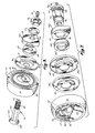
- Figure 3 is an exploded, perspective view of the trolley assembly of Figures 1 and 2;
- Figure 4 is an enlarged, end elevation of a portion of a second embodiment of the present trolley assembly invention illustrating a modified inner race and trolley bracket structure with portions shown in section;
- Figure 5 is a fragmentary, end elevation of a third embodiment of the present trolley assembly invention with portions shown in section including a trolley wheel assembly permanently secured to a stamped, sheet metal trolley bracket with a non-circular, hexagonal rivet;
- Figure 6 is a sectional, side elevation of the trolley assembly taken along plane VI-VI of Figure 5; and
- Figure 7 is an exploded, perspective view of the trolley assembly of Figures 5 and 6.
- Referring now to the drawings in greater detail, Figures 1 to 3 illustrate a
first embodiment 10 of the present trolley assembly invention including atrolley wheel assembly 12 non-rotationally secured to a support ortrolley bracket 45 by means of a non-circular support and retaining shaft orbolt 60.Trolley assembly 10 is designed for support and movement along a conventional I-beam overhead conveyor track (shown in phantom in Figure 1) such that a pair of such assemblies are secured in alignment on either side of the central vertical web of such a track. Figure 1 illustrates the manner in which a pair of thebrackets 45 are inserted in the middle of acentre link 56 of an overhead conveyor chain and spaced apart by a downwardly extending spacer orattachment 58 from which a work piece may be hung or suspended.Brackets 45 curve upwardly and around the lower wheel supporting flanges of the I-beam track to supportwheel assemblies 12 generally at a slight angle from the horizontal thereon. The track, spacer orattachment 58, andchain 56 form no part of the present invention. -
Trolley wheel assembly 12 includes a singleinner race member 14 preferably machined from steel and case hardened or otherwise treated having a partially circularinner raceway 16 on its outer circumference and a countersunk,conical recess 18 on one side leading to acentral opening 20.Opening 20 has a non- circular shape, preferably that of a regular polygon such as a hexagon, designed to match and slip over a correspondingly shaped support shaft or bolt 60 as will be more fully described below. Anouter race 22 is preferably also machined from steel and case hardened and includes a partially circularouter raceway 24 on its inner circumference radially aligned but spaced outwardly frominner raceway 16.Outer race member 22 also includes a crowned outer circumference engaging the slope of the I-beam track, and stepped, annular recesses orshoulders closure member 34 on the same side asinner race recess 18 and a portion of alabyrinth seal assembly 35 on ti-e opposite or bracket side ofinner race 14. Sinceinner race member 14 is one piece, a series of spherical ball bearing rolling elements is received between and withinraceways outer race 22 with respect to theinner race 14.Balls 30 are spaced apart and retained in their spaced relationship by a conventional cage orretainer 32. - As shown in Figure 1,
annular recess 26 receives aclosure disc member 34 which covers one end of the inner race member on the same side asrecess 18 along with the space between inner andouter race members Closure member 34, which is initially a dome shaped disc, is flexed or "oil- canned" into place in theannular recess 26 for secure retention. - On the side of
wheel assembly 12 opposite toclosure member 34 is thelabyrinth seal assembly 35.Seal assembly 35 includes an outer stepped or configured, annular shield or sealmember 36, an intermediate, annular, stepped shield or sealmember 38 and an inner annular generally L-shaped seal orshield member 40. Outer and intermediate shield orseal members hexagonal aperture bolt 60 in the same manner as doesinner race member 14.Seal members shaft 60 toward the outer race but include axially extending portions such that each includes portions spaced respectively outwardly of theinner seal member 40.Seal 40 is retained in a portion of annular steppedrecess 28 on the side of theouter race 22 opposite fromclosure member 34, as shown in Figure 1. The radially extending flanges of theseal members Shield 36 also includes a semi-circular weep hole ordrainage aperture 36a aligned with one of the flats inhexagonal aperture 37. When slipped overbolt shank 62 with the non-circular aperture at the bottom, weephole 36a is retained at the bottom ofwheel assembly 12 in radial alignment with the bottom ofbolt 60 so that any foreign matter or liquids entrapped within the wheel assembly can drain out properly. Theoverall seal assembly 35, except for its method of securement toshaft 60 as in the present invention, is as shown and described in United States Patent 3,537,725 entitled TROUGH-LIKE SEAL FOR ROLLER ASSEMBLY. - Also telescoped over shaft or
bolt 60 is a spacing member orcollar 42 forming an annular ring having radially extending side surfaces and a width slightly wider than the axial width ofseal member 36. Collar orring 42 includes a circular central aperture unlikeinner race member 14, orseal members bolt 60. In any event, compression force betweenbracket 45 andseal member 40, when the wheel assembly is attached to the bracket, will normally prevent rotation of the collar. - As is best seen in Figure 1, support member or
trolley bracket 45 is telescoped over shaft or bolt 60 outboard of spacer orcollar 42 by means of a noncircular, preferablyhexagonal aperture 46 equivalent in size to those ininner race member 14 andseal member Bracket 45 is stamped from sheet metal and includes a generally planar,wheel supporting area 48, a chainlink engaging end 50 and an intermediate connectingportion 52 which is designed to curve upwardly and outwardly around the I-beam support track for the trolley assembly.Bracket 45 also includes an outwardly extending peripheral ormarginal edge flange 54 which stiffens and strengthens the bracket.Bracket 45 may be any one of the various embodiments of trolley brackets shown in United States Patents 4,220,243; 4,210,238; 4,258,841; 4,266,657; or 4,266,658 all entitled CHAIN BRACKET WITH STRENGTHENED CHAIN SUPPORTS. - Of course, other support members such as castings or carriages for multi-wheel carriers in power and free overhead conveyors and/or in- floor conveyors can also be used with the present invention.
- As is best seen in Figures 1 and 3, support shaft or
bolt 60 includes shank orbody portion 62, which has the shape of a regular polygon, in this case a hexagon, an integral head having a conical undersurface 64, and an extending, threadedend portion 66. Theshank 62 has a series of elongated flat, planar areas forming an outer circumference having the cross-sectional hexagon shape. Other non-circular shapes, i.e., triangular, square, rectangular, pentagonal, or other polygons could also be used.Shank 62 may alternatively include a single non-circular area, such as a flat, planar area whileapertures -
Trolley wheel assembly 12,seal members spacer collar 42, andbracket 45 are assembled on support shaft orbolt 60 by first telescopinginner race member 14 over the threadedend portion 66 ofbolt 60 such that conical head surface 64 seats in the correspondingly shapedconical recess 18 on the inner race.Seal member 40 is secured inouter race 22 prior to such assembly. Thereafter,seal members hexagonal shank 62 ofbolt 60 such that they abut against one another and against the flat or planar side surface ofinner race member 14 opposite the side on whichrecess 18 is included.Collar 42 is then telescoped overshank 62 and against the flat or planar inner radial area ofseal member 36, following which wheelsupport area 48 ofbracket 45 is telescoped overhexagonal shank 62. - As will be understood from Figure 1, the length of the
hexagonal shank area 62 is slightly shorter than the combined widths of theinner race member 14 at the inner end ofrecess 18,seal members collar 42 andwheel support area 48 ofbracket 45. Alock washer 57 and a threadednut 59 are threaded on theend 66 of thebolt 60 to complete the assembly. Upon tightening,nut 59forces bracket 45,collar 42,seal member inner race member 14 againsthead 64 ofbolt 60 to retain them tightly in engagement with one another. Rotation ofrace member 14, seals 36, 38 andbracket 45 with respect to bolt 60 and one another is prevented by the interengagement ofnon-circular apertures bolt shank 62. Rotation ofcollar 42 is resisted by its engagement betweenbracket area 48 and the inner radial area ofseal 36. Alsobracket 45 and seal 36 do not rotate. Since the width ofcollar 42 is slightly wider than the over axial extent or width ofseal member 36, the bracketwheel support area 48 is spaced away from theseal 36 and therefore does not contact or interfere with its operation. - The final step in the assembly is to support the wheel and bracket structure on an appropriate support tool and to secure
closure member 34 inannular recess 26 on the outer side ofwheel assembly 12. The securement ofclosure member 34 effectively prevents the removal ofbolt 60 from the assembly even if thenut 59 andwasher 57 are removed and theentire wheel assembly 12 is removed frombracket 45. -
Trolley wheel assembly 12 may be relu- bricated by insertion of grease or other lubricant through a conventionally known Zerk-type grease fitting 68 secured in an axially extending bore orlubricant passageway 69 extending along the central axis ofbolt 60. Lubricant passes throughpassageway 69 into the space betweenbolt head 64 andclosure member 34 and moves radially outwardly to the space between theraceways elements 30. - Referring now to Figure 4, a modified embodiment 70 of the trolley assembly is shown wherein like numerals indicate like parts to
embodiment 10. Embodiment 70 includes the same outer race member (not shown) and shield or seal members (not fully shown), as described above in connection with Figures 1 to 3. However, a modified inner race assembly 72 is included having left and right annular, inner race rings 74, 76 together forming a partially circular inner raceway. Eachring flanges 78 of anannular hub 80 which retains the inner race parts together after insertion of a full complement of balls (not shown) which eliminate the need for a cage or retainer as was used at 32 in theassembly 10.Hub 80 includes a preferably hexagonal aperture adapted to slide over and fit closely aroundbolt shank 62, as well as a conical recess for receivingbolt head 64. - Embodiment 70 also includes a different, forged
trolley bracket 82 including awheel support head 84 having a non-circular, preferably hexagonally shaped aperture 85 therethrough.Head 84 includes an outwardly extendingprojection 86 having a radially extending, planar face surface which abuts against the inner radial area ofouter seal member 36 to clamp theseal members bolt 60 is the same as that described above in connection withassembly 10. The assembly procedure for the entire assembly 70 is the same as that forassembly 10 except that the need for aspacer collar 42 is eliminated because of the projectingface 86 on forgedbracket 82. Further, the three member inner race assembly 72 is telescoped overbolt 60 and againsthead 64 in the same manner as is single pieceinner race member 14 inembodiment 10. - The assembly procedure for
assemblies 10 and 70 illustrates an important advantage of the present invention. That is, when it is desired to removewheel assembly 12 frombracket 45 after the entire assembly has been installed in an overhead conveyor system, a workman need merely loosennut 59 with an appropriate wrench and need not worry about holdingbolt 60 against rotation during such loosening. Access to hold such bolt would be prevented in any event byclosure member 34. Such rotation will automatically be prevented by the engagement of the hexagonal bolt with thehexagonal aperture 46 inbracket 45 which bracket will, at that time, be secured in achain link 56 in the overhead conveyor system. Thus,wheel assembly 12, includingbolt 60, may be easily removed from the bracket without removingbracket 45 fromchain 56 and the overall conveyor system thereby greatly decreasing maintenance time and allowing immediate replacement ofwheel assembly 12 without disassembly of the bracket from the chain. - Referring now to Figures 5 to 7, a third embodiment 90 of the trolley assembly is shown wherein like numerals indicate like parts to those previously described. In this case, a closed trolley wheel assembly 12' is used wherein
outer race member 22,ball members 30,retainer cage 32, shield or sealmember 40, as well asclosure member 34 are all identical to those previously described. Inner race member 14' and seal members 36', 38' and 40' are very similar toinner race member 14, andseal members spacer collar 42 but includes a large circular aperture 44', best seen in Figure 7. Stamped trolley bracket 45', including wheel support area 48', has a larger hexagonal opening 46'. All of the hexagonal apertures and circular apertures through the various parts in assembly 90 are larger because of the use oflarger support rivet 92 having anintegral head 94 and ashank portion 96 which is larger thanbolt shank 62 and has a series of rectangular, flat or planar areas extending around its circumference to form the hexagonal cross-sectional shape matching that of the apertures through the various parts. Smaller rivets may also be used.Rivet 92 also includes an extending,formable end portion 98 which is permanently deformed or formed over to retain inner race member 14', seal members 36', 38', spacer collar 42' and bracket 45' tightly againstrivet head 94. Once formed over or rolled over, end 98 permanently retains the various parts together againsthead 94 such thatrivet 92 must be broken or destroyed to disassemble the assembly 90.Closure member 34 is secured onouter race member 22 afterrivet 92 is permanently installed through the various parts. - As shown in Figure 5, the interior of
rivet 92 is hollow. An axial extending, central circular passageway or bore 100, having a conventional Zerk-type grease fitting 68 inserted therein, leads to that hollow rivet interior. Lubricant may be inserted through the permanently installedrivet 92 by means of Zerk fitting 68 andpassageway 100 to the interior of the closed wheel 12'. The exterior circumference of theshank 96 ofrivet 92 also includes ribs or serrations in aband 102 extending around the circumference immediately adjacent the inside surface ofhead 94 to help retain the rivet on the bracket during assembly. - In the
various embodiments 10, 70 and 90, various parts of the wheel assembly not otherwise specified above are typically formed from metal by either machining or stamping as required. Of course thebrackets 45 and 45' are stamped from sheet metal via conventional transfer press or progressive die stamping processes, whilebracket 82 is forged with conventionally known forging processes. - It will now be understood that the present invention tightly and non-rotationally secures simultaneously the inner race member or members, shield or seal members, a spacer or collar, if any, as well as the bracket or support in a trolley or carriage assembly for use in conveyors, and especially overhead or floor conveyors. The flat surfaces on the bottom and other exterior areas of the support shaft, bolt or rivet help distribute the loads supported by the assembly to the track more evenly as compared to prior known cylindrical support shafts which support the weight along a line contact. In addition, the stress placed on the support shaft in compression need not be nearly as great since that force is not now relied upon for preventing rotation of the various parts. The present invention does not interfere with relubrication structures, contributes to reduced wear and longer life for the overall assembly, and allows use of smaller less bulky parts. Also, the present invention greatly eases assembly and disassembly since, even with closed or permanently lubricated wheels, support shafts having removable fasteners need not be held or secured against rotation during removal of the fastener because such holding or rotation resistance occurs automatically.
Claims (17)
Applications Claiming Priority (2)
| Application Number | Priority Date | Filing Date | Title |
|---|---|---|---|
| US06/208,285 US4367905A (en) | 1980-11-19 | 1980-11-19 | Wheeled support assembly for conveyors with locking and fastening feature |
| US208285 | 1980-11-19 |
Publications (2)
| Publication Number | Publication Date |
|---|---|
| EP0052984A1 EP0052984A1 (en) | 1982-06-02 |
| EP0052984B1 true EP0052984B1 (en) | 1984-06-13 |
Family
ID=22774015
Family Applications (1)
| Application Number | Title | Priority Date | Filing Date |
|---|---|---|---|
| EP81305380A Expired EP0052984B1 (en) | 1980-11-19 | 1981-11-12 | Improved trolley or carriage assembly |
Country Status (8)
| Country | Link |
|---|---|
| US (1) | US4367905A (en) |
| EP (1) | EP0052984B1 (en) |
| JP (1) | JPS57151463A (en) |
| AU (1) | AU7677981A (en) |
| BR (1) | BR8107509A (en) |
| CA (1) | CA1170602A (en) |
| DE (1) | DE3164227D1 (en) |
| ES (1) | ES8207080A1 (en) |
Families Citing this family (22)
| Publication number | Priority date | Publication date | Assignee | Title |
|---|---|---|---|---|
| US4759097A (en) * | 1983-04-26 | 1988-07-26 | Standex International Corporation | Wheel bracket assembly having two part wheel bracket and a method of making the wheel bracket assembly |
| CA1227912A (en) * | 1983-04-26 | 1987-10-13 | John W. Black | Two part wheel bracket assembly and a method of making it |
| FR2643956B1 (en) * | 1989-03-01 | 1994-09-16 | Roulement Cie Gle | BALL BEAD, ESPECIALLY FOR A MONORAIL OR THE LIKE HANDLING CHAIN |
| US5137196A (en) * | 1989-06-23 | 1992-08-11 | Deere & Company | Manner of rotatably mounting a bale wrapping material spreader roll to support walls |
| US5333956A (en) * | 1992-10-28 | 1994-08-02 | Hoffman Arnold R | Trolley wheel assembly |
| AU1949101A (en) | 1999-12-06 | 2002-08-12 | Ronald L. Plesh Sr. | Bearing wheel for conveyors and the like |
| US6663598B1 (en) | 2000-05-17 | 2003-12-16 | Scimed Life Systems, Inc. | Fluid seal for endoscope |
| US7025721B2 (en) * | 2004-01-29 | 2006-04-11 | Boston Scientific Scimed, Inc. | Endoscope channel cap |
| CA2464834A1 (en) * | 2004-04-19 | 2005-10-19 | Nordx/Cdt Inc. | Connector |
| WO2008100855A1 (en) | 2007-02-12 | 2008-08-21 | Boston Scientific Limited | Endoscope cap |
| WO2009023749A2 (en) * | 2007-08-14 | 2009-02-19 | Frost, Inc. | Trolley assembly with non-rotatable axle |
| US8388521B2 (en) * | 2008-05-19 | 2013-03-05 | Boston Scientific Scimed, Inc. | Integrated locking device with active sealing |
| US8343041B2 (en) | 2008-05-19 | 2013-01-01 | Boston Scientific Scimed, Inc. | Integrated locking device with passive sealing |
| US8702178B2 (en) * | 2009-12-23 | 2014-04-22 | Oconomowoc Mfg. Corp. | Trolley wheel technology |
| US8702335B2 (en) * | 2010-06-03 | 2014-04-22 | Preformed Line Products Company | Module clamp and fastener apparatus |
| DE102011080280A1 (en) * | 2011-08-02 | 2013-02-07 | Rsl Logistik Gmbh & Co. Kg | Carrier carrier for a suspension conveyor |
| EP2909494A1 (en) * | 2012-10-19 | 2015-08-26 | Aktiebolaget SKF | Rolling bearing with sealing subassembly |
| US10533634B2 (en) * | 2016-07-26 | 2020-01-14 | AMF automation Technologies, LLC | Axle and bearing for conveyor chain link |
| US10550881B2 (en) * | 2016-07-26 | 2020-02-04 | AMF automation Technologies, LLC | Axle and bearing for conveyor chain link |
| WO2019033006A1 (en) | 2017-08-11 | 2019-02-14 | Boston Scientific Scimed, Inc. | Biopsy cap for use with endoscope |
| US10889445B2 (en) * | 2019-05-01 | 2021-01-12 | Frost Tech Llc | Extended life conveyor chain trolley and method |
| US11498360B2 (en) | 2019-05-21 | 2022-11-15 | Ngs Capital Management, Llc | Hybrid bearing arrangement caster technology |
Family Cites Families (15)
| Publication number | Priority date | Publication date | Assignee | Title |
|---|---|---|---|---|
| US1617085A (en) * | 1926-08-20 | 1927-02-08 | Louden Machinery Co | Trolley wheel |
| US2117988A (en) * | 1932-08-08 | 1938-05-17 | Alvey Ferguson Co | Overhead traveling conveyer |
| US2512148A (en) * | 1948-08-13 | 1950-06-20 | Aerol Co Inc | Sealed wheel |
| US2976089A (en) * | 1958-06-24 | 1961-03-21 | Buschman Co E W | Roller wheel lubrication |
| US3086826A (en) * | 1959-11-30 | 1963-04-23 | Rapids Standard Co Inc | Bearing construction |
| US3469892A (en) * | 1968-06-03 | 1969-09-30 | Watsco Inc | Shielded-bearing roller for suspension devices |
| US3553765A (en) * | 1968-10-30 | 1971-01-12 | Frost & Son C L | Replaceable carriage wheel assembly |
| US3602150A (en) * | 1969-05-01 | 1971-08-31 | Frost & Son C L | Suspended trolley conveyor system |
| JPS5244502B2 (en) * | 1972-03-24 | 1977-11-08 | ||
| DE2425350C3 (en) * | 1974-05-25 | 1985-07-11 | SKF GmbH, 8720 Schweinfurt | Arrangement for the storage of drums for washing machines |
| US3971601A (en) * | 1974-12-02 | 1976-07-27 | C. L. Frost & Son, Inc. | Sanitary anti-friction trolley wheel |
| US4010987A (en) * | 1975-10-23 | 1977-03-08 | C. L. Frost & Son, Inc. | Removable seal for bearings |
| JPS5937241B2 (en) * | 1976-01-13 | 1984-09-08 | 株式会社クボタ | Transmission case protection structure |
| DE2834042A1 (en) * | 1977-08-09 | 1979-02-22 | Mayfran Inc | Belt conveyor roller assembly - has hub with lubricated tapering portion between sealing flanges at ends |
| US4154447A (en) * | 1978-05-19 | 1979-05-15 | Saginaw Products Corporation | Labyrinth seal for trolley wheels or the like |
-
1980
- 1980-11-19 US US06/208,285 patent/US4367905A/en not_active Expired - Lifetime
-
1981
- 1981-10-23 AU AU76779/81A patent/AU7677981A/en not_active Abandoned
- 1981-10-27 CA CA000388803A patent/CA1170602A/en not_active Expired
- 1981-11-12 EP EP81305380A patent/EP0052984B1/en not_active Expired
- 1981-11-12 DE DE8181305380T patent/DE3164227D1/en not_active Expired
- 1981-11-16 JP JP56183615A patent/JPS57151463A/en active Pending
- 1981-11-18 ES ES507232A patent/ES8207080A1/en not_active Expired
- 1981-11-18 BR BR8107509A patent/BR8107509A/en unknown
Also Published As
| Publication number | Publication date |
|---|---|
| AU7677981A (en) | 1982-05-27 |
| JPS57151463A (en) | 1982-09-18 |
| ES507232A0 (en) | 1982-09-01 |
| BR8107509A (en) | 1982-08-10 |
| ES8207080A1 (en) | 1982-09-01 |
| DE3164227D1 (en) | 1984-07-19 |
| CA1170602A (en) | 1984-07-10 |
| US4367905A (en) | 1983-01-11 |
| EP0052984A1 (en) | 1982-06-02 |
Similar Documents
| Publication | Publication Date | Title |
|---|---|---|
| EP0052984B1 (en) | Improved trolley or carriage assembly | |
| US4502738A (en) | Wheeled support assembly for conveyors with locking and fastening feature | |
| US4210372A (en) | Retainer for bearing lock nut | |
| US6357557B1 (en) | Vehicle wheel hub and brake rotor and method for producing same | |
| US4371362A (en) | Track roller system | |
| US3602150A (en) | Suspended trolley conveyor system | |
| US3977741A (en) | Wheel bearing assembly | |
| EP0698187B1 (en) | Connecting ring | |
| EP0048101A1 (en) | Bearing and universal joint assembly | |
| US5259676A (en) | Roller bearing spindle and hub assembly | |
| EP0007786A1 (en) | Wheel mounting and tapered roller bearing therefor | |
| US6915745B2 (en) | Self-lubricating overhead conveyor system | |
| US4798149A (en) | Wheel lock assembly | |
| US4763905A (en) | Seal retention and anti-rotation locking assembly | |
| US4671324A (en) | Jack bolt assembly | |
| US5330284A (en) | Apparatus for mounting and dismounting bearings | |
| US3036872A (en) | Bearing lock | |
| US4648729A (en) | Bearing weld ring | |
| EP0501506A2 (en) | A support unit for an idle element, in particular a non-driving wheel of a vehicle | |
| CA2390708C (en) | Bearing wheel for conveyors and the like | |
| CA1071277A (en) | Retainer for resiliently loading a bearing | |
| US20080095481A1 (en) | Differential wheel mounting for a railroad car | |
| US4854747A (en) | Eccentric bearing and hanger | |
| US8231279B2 (en) | Unit for supporting axle-shaft of go-karts | |
| US4023867A (en) | Roller bearing for backup rollers in multi-roll mills |
Legal Events
| Date | Code | Title | Description |
|---|---|---|---|
| PUAI | Public reference made under article 153(3) epc to a published international application that has entered the european phase |
Free format text: ORIGINAL CODE: 0009012 |
|
| AK | Designated contracting states |
Designated state(s): BE CH DE FR GB IT NL SE |
|
| 17P | Request for examination filed |
Effective date: 19820723 |
|
| GRAA | (expected) grant |
Free format text: ORIGINAL CODE: 0009210 |
|
| AK | Designated contracting states |
Designated state(s): BE CH DE FR GB IT LI NL SE |
|
| PG25 | Lapsed in a contracting state [announced via postgrant information from national office to epo] |
Ref country code: SE Effective date: 19840613 Ref country code: NL Effective date: 19840613 Ref country code: LI Effective date: 19840613 Ref country code: IT Free format text: LAPSE BECAUSE OF FAILURE TO SUBMIT A TRANSLATION OF THE DESCRIPTION OR TO PAY THE FEE WITHIN THE PRESCRIBED TIME-LIMIT;WARNING: LAPSES OF ITALIAN PATENTS WITH EFFECTIVE DATE BEFORE 2007 MAY HAVE OCCURRED AT ANY TIME BEFORE 2007. THE CORRECT EFFECTIVE DATE MAY BE DIFFERENT FROM THE ONE RECORDED. Effective date: 19840613 Ref country code: CH Effective date: 19840613 |
|
| REF | Corresponds to: |
Ref document number: 3164227 Country of ref document: DE Date of ref document: 19840719 |
|
| ET | Fr: translation filed | ||
| REG | Reference to a national code |
Ref country code: CH Ref legal event code: PL |
|
| NLV1 | Nl: lapsed or annulled due to failure to fulfill the requirements of art. 29p and 29m of the patents act | ||
| PGFP | Annual fee paid to national office [announced via postgrant information from national office to epo] |
Ref country code: FR Payment date: 19841116 Year of fee payment: 4 |
|
| PGFP | Annual fee paid to national office [announced via postgrant information from national office to epo] |
Ref country code: DE Payment date: 19841219 Year of fee payment: 4 |
|
| PGFP | Annual fee paid to national office [announced via postgrant information from national office to epo] |
Ref country code: BE Payment date: 19841231 Year of fee payment: 4 |
|
| PLBE | No opposition filed within time limit |
Free format text: ORIGINAL CODE: 0009261 |
|
| STAA | Information on the status of an ep patent application or granted ep patent |
Free format text: STATUS: NO OPPOSITION FILED WITHIN TIME LIMIT |
|
| 26N | No opposition filed | ||
| PG25 | Lapsed in a contracting state [announced via postgrant information from national office to epo] |
Ref country code: GB Effective date: 19881112 |
|
| PG25 | Lapsed in a contracting state [announced via postgrant information from national office to epo] |
Ref country code: BE Effective date: 19881130 |
|
| BERE | Be: lapsed |
Owner name: C.L. FROST & SON INC. Effective date: 19881130 |
|
| GBPC | Gb: european patent ceased through non-payment of renewal fee | ||
| PG25 | Lapsed in a contracting state [announced via postgrant information from national office to epo] |
Ref country code: FR Free format text: LAPSE BECAUSE OF NON-PAYMENT OF DUE FEES Effective date: 19890731 |
|
| PG25 | Lapsed in a contracting state [announced via postgrant information from national office to epo] |
Ref country code: DE Effective date: 19890801 |
|
| REG | Reference to a national code |
Ref country code: FR Ref legal event code: ST |